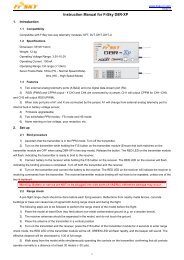
【DECLARATION】 Thanks for purchasing HOBBYWING ... - HiModel
【DECLARATION】 Thanks for purchasing HOBBYWING ... - HiModel
【DECLARATION】 Thanks for purchasing HOBBYWING ... - HiModel

You also want an ePaper? Increase the reach of your titles
YUMPU automatically turns print PDFs into web optimized ePapers that Google loves.
User Manual of XERUN-80A and XERUN-150A Brushless ESC www.hobbywing.com Doc Ver: HW-09-80150-090710 Page 1 of 4<br />
<strong>【DECLARATION】</strong><br />
<strong>Thanks</strong> <strong>for</strong> <strong>purchasing</strong> <strong>HOBBYWING</strong> Electronic Speed Controller (ESC). High power system <strong>for</strong> RC model<br />
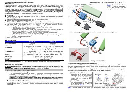
Note1: The small black female<br />
can be very dangerous, please read this manual carefully. In that we have no control over the correct use,<br />
connector coming out from the ESC<br />
installation, application, or maintenance of our products, no liability shall be assumed nor accepted <strong>for</strong> any<br />
is used <strong>for</strong> connecting with the<br />
damages, losses or costs resulting from the use of the product. Any claims arising from the operating,<br />
cooling fan of the brushless motor.<br />
failure of malfunctioning etc. will be denied. We assume no liability <strong>for</strong> personal injury, consequential<br />
damages resulting from our product or our workmanship. As far as is legally permitted, the obligation to<br />
compensation is limited to the invoice amount of the affected product.<br />
【FEATURES】<br />
► Compatible with all sensorless brushless motors and most of sensored brushless motors such as LRP,<br />
SpeedPassion, Novak, etc.<br />
► Seamlessly change to sensorless working mode when the sensor cable is broken.<br />
► Excellent start-up, acceleration and linearity features.<br />
► Built-in switch mode BEC has a powerful output to supply all the electronic equipments.<br />
► Firmware can be updated through an USB adapter on the advanced LCD Program Box (Optional equipment).<br />
► User programmable. Easily programmed with the “SET” button on the ESC and also compatible with the 3<br />
digital LEDs Program Card and the advanced professional LCD Program Box.<br />
3 running modes (Forward mode, Forward/Reverse mode, Rock Crawler mode)<br />
4 steps of maximum reverse <strong>for</strong>ce adjustment.<br />
Proportional ABS brake function with 4 steps of maximum brake <strong>for</strong>ce adjustment, 8 steps of<br />
drag-brake <strong>for</strong>ce adjustment and 4 steps of initial brake <strong>for</strong>ce adjustment.<br />
9 start modes (Also called “Punch”) from “very soft (Level 1)” to “very aggressive (Level 9)”.<br />
<br />
<br />
8 steps of timing adjustment to suitable <strong>for</strong> all brushless motors.<br />
Multiple protection features: Low voltage cut-off protection / Over-heat protection / Throttle signal loss<br />
protection / Motor blocked protection.<br />
► Splash proof and dustproof.<br />
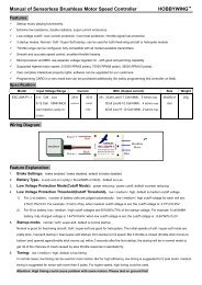
【SPECIFICATIONS】<br />
Model XERUN-80A XERUN-150A<br />
Cont./ Burst Current 80A / 380A 150A/950A<br />
Resistance 0.0006 ohm 0.0002 ohm<br />
Suitable Car<br />
1/8 on-road, off-road and monster 1/5, 1/8 on-road, off-road and monster<br />
RTR applications<br />
Super powerful applications<br />
Sensored and sensorless Brushless Motors<br />
Suitable Motor<br />
≥6T, KV≤2400<br />
≥4.5T, KV≤3000 (Works with 4S Lipo)<br />
The 80A ESC works with 4S Lipo ≥6T, KV≤2400 (Works with 6S Lipo)<br />
Battery 6-12 cells NiMH or 2-4 cells Li-Po 6-18 cells NiMH or 2-6 cells Li-Po<br />
BEC Output<br />
5.75V@3A Switch mode built-in BEC<br />
Dimension<br />
58mm(L) * 46.5mm(W) * 35mm(H)<br />
Weight<br />
105g (Wires not included)<br />
Cooling Fan Working Voltage 5V, maximum 8V. (The fan gets the power supply from the built-in BEC)<br />
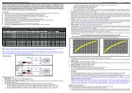
If there are 2 battery packs need to be connected in series, please refer to the following picture:<br />
【BEGIN TO USE THE NEW ESC】<br />
WARNING! THIS BRUSHLESS SYSTEM IS VERY POWERFUL! FOR SAFETY, PLEASE ALWAYS KEEP THE<br />
WHEELS AWAY FROM THE TRACK WHEN YOU BEGIN TO SWITCH ON THE ESC.<br />
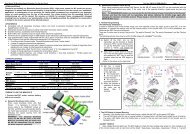
1. Connect The ESC, Motor, Receiver, Battery And Servo<br />
A) Sensored brushless motor wiring<br />
When using brushless motor with Hall Sensor,it is necessary to connect the sensor cable to the<br />
“SENSOR” port on the ESC, and ESC can automatically identify the motor type (sensored or sensorless)<br />
by detecting the signal coming from the SENSOR port.<br />
WARNING! For sensored brushless motor, the #A, #B, #C wires of the ESC MUST be connected<br />
with the motor wire #A, #B, #C respectively. Do not change the wires sequence optionally!<br />
B) Sensorless brushless motor wiring<br />
When using brushless motor without Hall Sensor, the #A, #B, #C wires of the ESC can be connected with the<br />
motor wires freely (without any sequence). If the motor runs in the opposite direction, please swap any two wire<br />
connections.<br />
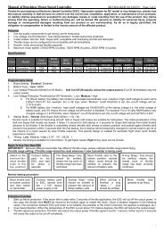
2. Throttle Range Setting (Throttle Range Calibration)<br />
In order to make the ESC fit the throttle range, you must calibrate it when you begin to use a new ESC, or a new<br />
transmitter, or change the settings of neutral position of the throttle stick, ATV or EPA parameters, etc. Otherwise<br />
the ESC cannot work properly.<br />
There are 3 points need to be set, they are “Top point of <strong>for</strong>ward”, “Top point of backward” and the neutral point.<br />
The following pictures show how to set the throttle range with a Futaba TM transmitter.<br />
A) Switch off the ESC, turn on the<br />
transmitter, set the direction of throttle<br />
channel to ”REV”, set the “EPA/ATV”<br />
value of throttle channel to “100%”, and<br />
disable the ABS function of your<br />
transmitter.<br />
B) Hold the “SET” key and then switch on<br />
the ESC, and release the “SET” key as<br />
soon as possible when the red LED<br />
begins to flash. (Note2 )<br />
Note2: If you don’t release the “SET” key as soon as the red LED begins to flash, the ESC will enter the program
User Manual of XERUN-80A and XERUN-150A Brushless ESC www.hobbywing.com Doc Ver: HW-09-80150-090710 Page 2 of 4<br />
mode, in such a case, please switch off the ESC and re-calibrate the throttle range again from step A to step D.<br />
When you move the throttle stick from <strong>for</strong>ward zone to backward zone <strong>for</strong> the first time (The 1 st “click”), the ESC<br />
begins to brake the motor, the motor speeds down but it is still running, not completely stopped, so the backward<br />
action is NOT happened immediately. When the throttle stick is moved to the backward zone again (The 2 nd “click”),<br />
if the motor speed is slowed down to zero (i.e. stopped), the backward action will happen. The “Double-Click”<br />
method can prevent mistaken reversing action when the brake function is frequently used in steering.<br />
By the way, in the process of brake or reverse, if the throttle stick is moved to <strong>for</strong>ward zone, the motor will run<br />
<strong>for</strong>ward at once.<br />
“Forward/Reverse” mode uses “Single-click” method to make the car go backward. When you move the<br />
throttle stick from <strong>for</strong>ward zone to backward zone, the car will go backward immediately. This mode is usually used<br />
<strong>for</strong> the Rock Crawler.<br />
C) Set the 3 points according to the steps<br />
shown as the pictures on the right side.<br />
1) The neutral point<br />
Move the throttle stick at the neutral point,<br />
and then click the SET key, the green LED<br />
flashes 1 time.<br />
2) The end point of <strong>for</strong>ward direction<br />
Move the throttle stick at the end point of<br />
<strong>for</strong>ward direction, and then click the SET<br />
key, the green LED flashes 2 times.<br />
3) The end point of backward direction<br />
Move the throttle stick at the end point of<br />
backward direction, and then click the SET<br />
key, the green LED flashes 3 times.<br />
D) Throttle range is calibrated; motor can be<br />
started after 3 seconds.<br />
3. Check The LED Status In Normal Running<br />
► Normally, if the throttle stick is in the neutral range, neither the red LED nor the green LED lights.<br />
► The red LED lights when the car is running <strong>for</strong>ward or backward and it will flash quickly when the car is braking.<br />
► The green LED lights when the throttle stick is moved to the top point (end point) of the <strong>for</strong>ward zone or<br />
backward zone.<br />
4. Check The Lipo Cells Setting If You Are Using Lithium Battery<br />
If you are using Lipo battery, we strongly suggest setting the “Lipo Cells” programmable item manually to avoid the<br />
over-discharge problem. Please read the instructions on page 3.<br />
In normal case, when the ESC is switched on, the motor will emit several “Beep” tones to express the cells amount<br />
of the battery pack. For example, “Beep-Beep-” means 2s Lipo, “Beep-Beep-Beep-” means 3s Lipo, etc.<br />
【PROGRAM THE ESC】<br />
1. Programmable Items List (The italics texts in the <strong>for</strong>m are the default settings)<br />
Programmable<br />
Programmable Value<br />
Items<br />
1 2 3 4 5 6 7 8 9<br />
Basic Items<br />
1. Running Mode<br />
Forward<br />
with Brake<br />
Forward/Reverse<br />
with Brake<br />
Forward and<br />
Re verse<br />
2.2. Drag Brake Force: Set the amount of drag brake applied at neutral throttle to simulate the slight braking<br />
effect of a neutral brushed motor while coasting.<br />
2.3. Low Voltage Cut-Off: The function prevents the lithium battery pack from over discharging. The ESC detects<br />
the battery’s voltage at any time, if the voltage is lower than the threshold <strong>for</strong> 2 seconds, the output power will be<br />
reduced 70%, after 10 seconds the output will be completely stopped, and the red LED flashes in such a way:<br />
“☆-☆-, ☆-☆-, ☆-☆-”.<br />
There are 6 preset options <strong>for</strong> this item. You can customize the cutoff threshold by using an advanced LCD program<br />
box (optional equipment) to trim it with a step of 0.1V, so it will be more suitable <strong>for</strong> all kinds of batteries (NiMH,<br />
NiCd, Li-ion, Lipo, LFP,etc). Please always keep in mind that the customized value is not <strong>for</strong> each cell, it is <strong>for</strong><br />
the WHOLE battery pack.<br />
2.4. Start Mode (Also called “Punch”): Select from “Level1” to “Level9” as your like, Level1 has a very soft<br />
start effect, while level9 has a very aggressive start effect. From Level1 to Level9, the start <strong>for</strong>ce is increasing.<br />
Please note that if you choose “Level7” to “Level9” mode, you must use good quality battery pack with powerful<br />
discharge ability, otherwise these modes cannot get the burst start effect as you want. If the motor cannot run<br />
smoothly (the motor is trembling), it may caused by the weak discharge ability of the battery pack, please choose a<br />
better battery or increase the gear rate (Use a smaller pinion).<br />
2.5. Maximum Brake Force: The ESC provides proportional brake function. The brake <strong>for</strong>ce is related to the<br />
position of the throttle stick. Maximum brake <strong>for</strong>ce refers to the <strong>for</strong>ce when the throttle stick is located at the top<br />
point of the backward zone. A very large brake <strong>for</strong>ce can shorten the brake time, but it may damage the gears.<br />
2.6. Maximum Reverse Force: Sets how much power will be applied in the reverse direction. Different value<br />
makes different reverse speed.<br />
2.7. Initial Brake Force: It is also called “minimum brake <strong>for</strong>ce”, and it refers to the <strong>for</strong>ce when the throttle stick is<br />
located at the initial position of the backward zone. The default value is equal to the drag brake <strong>for</strong>ce, so the brake<br />
effect can be very smoothly.<br />
2.8. Throttle Neutral Range: Please refer to the following picture to adjust the neutral range as your like.<br />
2.Drag Brake Force 0% 5% 10% 20% 40% 60% 80% 100%<br />
3.Low Voltage<br />
Cut-Off Threshold<br />
Non-Protection 2.6V/Cell 2.8V/Cell<br />
4.Start Mode(Punch) Level1 Level2 Level3 Level4 Level5 Level6 Level7 Level8 Level9<br />
Advanced Items<br />
2. Explanation For Each Programmable Item<br />
2.1. Running Mode: With “Forward with Brake” mode, the car can go <strong>for</strong>ward and brake, but cannot go backward,<br />
this mode is suitable <strong>for</strong> competition; “Forward/Reverse with Brake” mode provides backward function, which is<br />
suitable <strong>for</strong> daily training.<br />
Note: “Forward/Reverse with Brake” mode uses “Double-click” method to make the car go backward.<br />
3.0V<br />
/Cell<br />
5.Max Brake Force 25% 50% 75% 100%<br />
6.Max Reverse Force 25% 50% 75% 100%<br />
7.Initial Brake Force<br />
= Drag Brake<br />
Force<br />
0% 20% 40%<br />
8.Neutral Range 6% (Narrow) 9% (Normal) 12% (Wide)<br />
9.Timing<br />
(Only <strong>for</strong> sensorless<br />
0.00 ° 3.75 ° 7.50 ° 11.25 ° 15.00 ° 18.75 ° 22.50° 26.25°<br />
motor)<br />
10.Over-heat Protection Enable Disable<br />
3.2V<br />
/Cell<br />
11.Motor Rotation<br />
Counter<br />
Clockwise<br />
Clockwise<br />
12.Lipo Cells Auto Calculate 2 Cells 3 Cells 4 Cells 5 Cells 6 Cells<br />
3.4V<br />
/Cell<br />
2.9. Timing: The “timing” item is usable <strong>for</strong> both sensored and sensorless brushless motors. There are many<br />
differences among structures and parameters of different brushless motors, so a fixed timing ESC is difficult to<br />
compatible with all brushless motors. It is necessary to make the timing value programmable. Please select the<br />
most suitable timing value according to the motor you are just using. Generally, higher timing value brings out<br />
higher power output, but the whole efficiency of the system will be slightly lower down.<br />
2.10. Over-Heat Protection: If the function is activated, the output power will be cut-off when the temperature of<br />
the ESC or the internal temperature of the sensored brushless motor is higher than a factory-preset value <strong>for</strong> 5<br />
seconds. When the protection happens, the Green LED will flash.<br />
When the ESC is over-heat: The Green LED flashes as “☆-, ☆-, ☆-”.
User Manual of XERUN-80A and XERUN-150A Brushless ESC www.hobbywing.com Doc Ver: HW-09-80150-090710 Page 3 of 4<br />
When the motor is over-heat: The Green LED flashes as “☆-☆-, ☆-☆-, ☆-☆-”.<br />
Note3: The motor over-heat protection function is only available <strong>for</strong> the sensored brushless motor made by<br />
Flow chart: Program the ESC with the SET key<br />
Hobbywing Technology Co., Ltd. For motors made by other manufacturers, this function maybe not available or<br />
the protection point doesn’t match the design of the ESC, please disable the over-heat protection function in such a<br />
case.<br />
2.11. Motor Rotation: You can use this item to change the rotation direction. Face to the motor shaft (That means<br />
the rear cover of the motor is far from your face), and move the throttle stick to the top point of the <strong>for</strong>ward zone. If<br />
this item is set to “CCW”, the shaft runs counter-clockwise; If this item is set to “CW”, the shaft runs clockwise.<br />
2.12. Lipo Cells: We strongly suggest setting the “Lipo Cells” item manually. Because the normal voltage of each<br />
Lipo cell varies from 2.6V to 4.2V, it is quite difficult to calculate the cells number of a discharged Lipo battery pack.<br />
If it is calculated incorrectly, the Low Voltage Cutoff Protection function may work abnormally, so the option “Auto<br />
Calculate” is only available <strong>for</strong> 2s, 4s and 6s Lipo. If the voltage of the battery pack is lower than 8.8V, it is judged as<br />
a 2s Lipo; If the voltage is between 8.8V to 17.6V, it is judged as a 4s Lipo; If the voltage is higher than 17.6V, it is<br />
judged as a 6S Lipo. So in order to make the Low Voltage Cutoff Protection function always works correctly, please<br />
set the “Lipo Cells” item manually.<br />
3. Program Methods<br />
A) Program the ESC with LED program card (Optional equipment )<br />
Please refer to the user manual of LED program card.<br />
B) Program the ESC with advanced LCD program box (Optional equipment )<br />
Please refer to the user manual of LCD program box.<br />
C) Program the ESC with the SET button on the ESC<br />
Please refer to the instructions at the right side.<br />
4. Reset All Items To Default Values<br />
At any time when the throttle is located in neutral zone (except in the throttle calibration process or ESC program<br />
mode), hold the “SET” key <strong>for</strong> over 3 seconds, the red LED and green LED will flash at the same time , which<br />
means each programmable item has be reset to its default value.<br />
【ALERT TONES】<br />
1. Input voltage abnormal alert tone: The ESC begins to check the input voltage when power on, if the voltage is<br />
out of the normal range, such an alert tone will be heard: “beep-beep-, beep-beep-, beep-beep-” (There is 1 second<br />
interval between every group of “beep-beep-” tone).<br />
2. Throttle signal abnormal alert tone: When the ESC can’t detect the normal throttle signal, such an alert tone<br />
will be heard: “beep-, beep-, beep-” (There is 2 seconds interval between every “beep-” tone).<br />
Note4:<br />
In the program process, when the LED is flashing, the motor will emit “Beep” tone at the same time.<br />
If the number “N” is bigger than the “5”, we use a long time flash and long “Beep---” tone to represent “5”, so it<br />
is easy to identify the items with bigger series number.<br />
For example, if the LED flashes as the following:<br />
“A long time flash + 1 short time flash” (Motor sounds “Beep---Beep”) = the No. 6 item<br />
“A long time flash + 2 short time flashes” (Motor sounds “Beep---BeepBeep”) = the No. 7 item<br />
“A long time flash + 3 short time flashes” (Motor sounds “Beep---BeepBeepBeep”) = the No. 8 item<br />
……<br />
And so on.
User Manual of XERUN-80A and XERUN-150A Brushless ESC www.hobbywing.com Doc Ver: HW-09-80150-090710 Page 4 of 4<br />
【MAIN APPLICATIONS】<br />
【WARRANTY INFORMATIONS】<br />
The XERUN series ESC is warranted <strong>for</strong> 240 days from the date of production to be free of material and<br />
ESC Motor Pinion Gear Rate Applications<br />
workmanship defects. This warranty does not cover abuse, neglect, or damage due to incorrect wiring, over voltage<br />
XERUN Diameter=41 M1, 13T 1/8 Off-Road: 1/8 EP Off-Road Truggy /Buggy/ Monster RTR.<br />
or over loading.<br />
Length=65 (Truggy / Buggy) 10-16 1/8 NP Off-Road Truggy or Buggy changes to An itemed Warranty Card must accompany any product returned <strong>for</strong> warranty work. The serial number on the<br />
-80A<br />
KV=2300<br />
EP.<br />
warranty card must be identical with the serial number of the ESC.<br />
1/8 Monster:<br />
Please browse http://www.hobbywing.com/english/kf.asp <strong>for</strong> more detail warranty in<strong>for</strong>mation.<br />
16-21 4 cells Lipo battery is recommended.<br />
XERUN<br />
-150A<br />
Diameter=41<br />
Length=65<br />
KV=2300<br />
M1, 13T<br />
(Truggy / Buggy)<br />
32Pitch, 19T<br />
(Monster)<br />
1/8 Off-Road:<br />
10-15.5<br />
1/8 Monster:<br />
13-21<br />
1/8 EP Truggy / Buggy and Monster.<br />
Very powerful and reliable. Brings out incredible<br />
speed.<br />
4 cells Lipo battery is recommended.<br />
XERUN<br />
-150A<br />
Diameter=42.5<br />
Length=75<br />
KV=2000<br />
32 Pitch<br />
4 cells Lipo: 21T<br />
6 cells Lipo: 17T<br />
4 Cells Lipo:<br />
12-19<br />
6 Cells Lipo:<br />
15-21<br />
1/8 EP Monster.<br />
Super and crazy powerful.<br />
4 cells or 6 cells Lipo battery is recommended.<br />
【TROUBLE SHOOTING】<br />
Trouble Possible Reason Solution<br />
The connections between Check the power connections<br />
battery pack and ESC are not Replace the connectors<br />
correct<br />
After power on, motor doesn’t work,<br />
and the cooling fan doesn’t work<br />
After power on, motor can’t work,<br />
but emits “beep-beep-, beep-beep-”<br />
alert tone. (Every group of<br />
“beep-beep-” has a time interval of<br />
1 second )<br />
After power on, red LED always<br />
lights, the motor doesn’t work<br />
The motor runs in the opposite<br />
direction when it is accelerated<br />
The motor suddenly stops running<br />
while in working state<br />
When accelerating quickly, the<br />
motor stops or trembles<br />
When the throttle stick is in the<br />
neutral range, the red LED and the<br />
green LED flashes synchronously<br />
Input voltage is abnormal, too<br />
high or too low<br />
Throttle signal is abnormal<br />
1)The wire connections between<br />
ESC and the motor are not<br />
correct<br />
2)The chassis is different from<br />
the popular design<br />
The throttle signal is lost<br />
The ESC has entered the Low<br />
Voltage Protection Mode or<br />
Over-heat Protection Mode<br />
1) The battery has a bad<br />
discharge per<strong>for</strong>mance<br />
2) The gear rate is too small<br />
3) The “Start Mode (Punch)” of<br />
the ESC is too aggressive<br />
The motor is a sensored motor,<br />
but the ESC detects abnormal<br />
signal from the sensor, so it<br />
changes to sensorless mode<br />
automatically<br />
Check the voltage of the battery pack<br />
Plug the control wire into the throttle<br />
channel of the receiver correctly.<br />
1) For sensorless motor: Swap any two<br />
wire connections between the ESC and<br />
the motor. Or use the method #2<br />
2) For sensored motor: Please check<br />
the wire connections, they must be A-A,<br />
B-B, C-C respectively. If the connections<br />
are correct, please change the “Motor<br />
Rotation” programmable item to<br />
“CW(Clockwise)”<br />
Check the transmitter and the receiver<br />
Check the signal wire from the throttle<br />
channel of your receiver<br />
Red LED flashing means Low voltage<br />
protection. Green LED flashing means<br />
Over-heat protection<br />
1) Use a better battery<br />
2) Use lower KV motor or change the<br />
gear rate, choose smaller pinion<br />
3) Select a softer option <strong>for</strong> the “Start<br />
Mode (Punch)”<br />
1) Check the connection of Hall sensor<br />
cable to make it firmly connect the motor<br />
with the ESC<br />
2) The Hall sensors in the motor are<br />
damaged, please change the motor<br />
<strong>HOBBYWING</strong> TECHNOLOGY CO., LTD.<br />
http://www.hobbywing.com