GA510 Tail-lock Gyro User's Manual - RCGroups.com
GA510 Tail-lock Gyro User's Manual - RCGroups.com
GA510 Tail-lock Gyro User's Manual - RCGroups.com

You also want an ePaper? Increase the reach of your titles
YUMPU automatically turns print PDFs into web optimized ePapers that Google loves.
<strong>GA510</strong> <strong>Tail</strong>-<strong>lock</strong> <strong>Gyro</strong> Instruction <strong>Manual</strong><br />
<strong>GA510</strong> <strong>Tail</strong>-Lock <strong>Gyro</strong> Instruction <strong>Manual</strong><br />
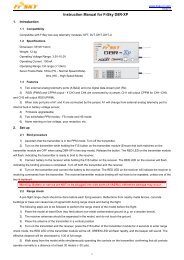
The gyro series developed by ASSAN include GA410, GA420, <strong>GA510</strong>, GA620, etc. This manual is<br />
for <strong>GA510</strong> High-Performance <strong>Tail</strong>-<strong>lock</strong> <strong>Gyro</strong>.<br />
<strong>GA510</strong> is a high-performance tail-<strong>lock</strong> gyro specially optimized and designed for RC 3D helicopters.<br />
Equipped with a big size LCD display, it’s also with some outstanding characteristics, such as super<br />
friendly man-machine interface, practical useful default/programable functions, wide type servos<br />
adaption and above all it’s with good tail-<strong>lock</strong> performance.<br />
Main Technical Characteristics<br />
◇ Sensor: quartz sensor<br />
◇ System control: AVCS (Angular Vector Control System)<br />
◇ Dual working condition: <strong>Tail</strong>-<strong>lock</strong> mode and Normal mode<br />
◇ Big size LCD display: the working status displayed on the LCD, which enables the setting all<br />
visually and easily.<br />
◇ Support multiple tail servos: 1520us-pulse-width digital servos and new 760us narrow<br />
pulse-width servos.<br />
Specifications<br />
1. Working voltage: DC 3.3 ~9V<br />
2. Working current: 40 mA<br />
3. Working temperature: -5℃ ~ 60℃<br />
4. External dimensions: 38 × 30 × 17 mm<br />
5. Weight: 20g<br />
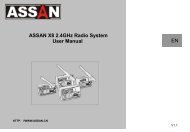
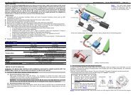
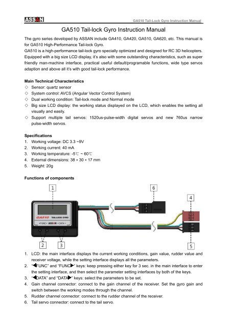
Functions of <strong>com</strong>ponents<br />
1. LCD: the main interface displays the current working conditions, gain value, rudder value and<br />
receiver voltage, while the setting interface displays all the parameters.<br />
2. “ FUNC” and “FUNC ” keys: keep pressing either key for 3 sec. in the main interface to enter<br />
the setting interface, and then select the parameter setting interfaces by both of the keys.<br />
3. “ DATA” and “DATA ” keys: select the parameters to be set.<br />
4. Gain channel connector: connect to the gain channel of the receiver. Set the gyro gain and<br />
switch between the working modes through the channel.<br />
5. Rudder channel connector: connect to the rudder channel of the receiver.<br />
6. <strong>Tail</strong> servo connector: connect to the tail servo.
<strong>GA510</strong> <strong>Tail</strong>-Lock <strong>Gyro</strong> Instruction <strong>Manual</strong><br />
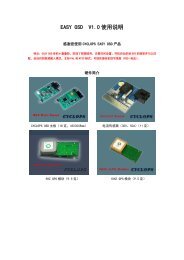
Installation<br />
When installing <strong>GA510</strong> <strong>Tail</strong>-<strong>lock</strong> <strong>Gyro</strong>, please stick the gyro to the stable place of the helicopter with<br />
the double-sided tape inside the packing box. The bottom of the gyro shall be perpendicular to the<br />
main axis of the helicopter (see the figure below). The G510 <strong>Tail</strong>-<strong>lock</strong> <strong>Gyro</strong> used on the RC electric<br />
helicopter shall be at least 10cm away from the motor. Do not install the gyro at the exhaust outlet<br />
or any places of heat to avoid the possible disturbance.<br />
Display and setting<br />
1. Power on<br />
When the gyro’s powered on (the transmitter must powered on first), <strong>GA510</strong> will display the<br />
following interfaces in sequence. Pay attention that before the main interface appeared, don’ t move<br />
the stickers, the gyro and the helicopter anyway.
<strong>GA510</strong> <strong>Tail</strong>-Lock <strong>Gyro</strong> Instruction <strong>Manual</strong><br />
2. Error prompt<br />
If there is any failure during the power-on process, the following error prompt will appear:<br />
The rudder channel is not connected properly or transmitter power wasn’t turned<br />
on. Please check the connection of the signal wire between the gyro and the<br />
rudder channel of the receiver or turn on transmitter power.<br />
The gain channel is not connected properly. Please check the connection of the<br />
signal wire between the gyro and the gain channel in the receiver.<br />
Internal error in gyro. If the problem cannot be fixed after turn off the power and<br />
restart, please return the gyro to the manufacturer for repair.<br />
3. Main interface<br />
Gain value<br />
Rudder value<br />
Receiver battery voltage<br />
Working Mode<br />
Two working mode as the follows:<br />
<strong>Tail</strong>-<strong>lock</strong> mode<br />
Normal mode<br />
4. Function<br />
Press “ FUNC” or “FUNC ” for 3 sec. to enter the setting interface, then selected by the two keys.<br />
<strong>GA510</strong> gyro’s functions include:<br />
<strong>Gyro</strong> control directions<br />
Servo types<br />
Servo center trim<br />
Two-direction servo limit adjustment<br />
Adjustment of rudder stick response smoothness<br />
Static drift correction
<strong>GA510</strong> <strong>Tail</strong>-Lock <strong>Gyro</strong> Instruction <strong>Manual</strong><br />
5. Setting<br />
1) <strong>Gyro</strong> control directions<br />
The gyro has two movement directions, namely NOR and REV. Lift the helicopter and turn the head<br />
of the helicopter left. If the sway of the tail servo is in the same direction when turning right the<br />
rudder controller on the transmitter, the control direction of the gyro is corrected set. If the direction<br />
is not correct, press “ DATA” or “DATA ” key to change the setting value of the control directions.<br />
The step above is most important. If the control direction of the gyro is wrong , the helicopter may<br />
have the danger of rotating at high speed when taking off, therefore please check it again whether<br />
the control direction of the gyro is in correctly set.<br />
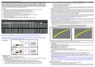
2) Selection of servo types<br />
The typical marketed tail servos can be classified into 3 different types according to the frame rate /<br />
pulse width, see the table below. If you used is not included in the table, please select the type<br />
according to the applicable frame rate / pulse width provided by the manufacturer. Be careful that<br />
the incorrect selection may cause the damage or decrease the performance or life of the servo.<br />
1520us / 250Hz 1520us / 333Hz 760us / 333Hz<br />
JR 810G Airtionics 94758 Futaba BLS251<br />
JR 2700G Airtionics 94761 Futaba S9251<br />
JR 8700G Futaba S3153 Futaba S9256<br />
Sky HDS-577 Futaba S3154 LogicTech 6100G<br />
Sky HDS-877 Futaba S9253 MKS DS8910<br />
Futaba S9254<br />
Futaba S9257<br />
Futaba S9650<br />
JR 3400G<br />
JR 8900G<br />
Hitec HS-5925MG<br />
Hitec HS-6965HB<br />
LogicTech 2100G<br />
Robbe FS61BB<br />
Sanwa ERG-WRX
<strong>GA510</strong> <strong>Tail</strong>-Lock <strong>Gyro</strong> Instruction <strong>Manual</strong><br />
3) Servo center trim<br />
Press “ DATA” or “DATA ” key to adjust the center value of the servo between -100 and 100. It is<br />
re<strong>com</strong>mended to adjust the rocker arm position of the servo at first. After the center position is<br />
basically appropriate, trim the center position with this function. Try to avoid the large-scale<br />
adjustment on the center of the servo.<br />
4) Two-direction servo limit adjustment<br />
Turn the rudder stick full rudder to one direction, then press “ DATA” or “DATA ” to adjust the limit<br />
to make the servo reach the maximum movement limit of the tail pitch sliding sleeve in this direction,<br />
and ensure that no over limit occurs in the process. Set the other direction with the same method.<br />
The adjustable range of the two-direction limits is 30% - 160%.<br />
5) Adjustment of rudder stick response smoothness<br />
Press “ DATA” or “DATA ” to adjust the response smoothness of the rudder stick within the range<br />
of 0% - 25%. This function adjusts the “hard” and “soft” feel in the response of the gyro to the rudder<br />
stick. The user may adjust the smoothness according to his own control feeling.<br />
6) Static drift correction<br />
In <strong>Tail</strong>-<strong>lock</strong> mode, if the tail is slowly drifting when the helicopter in hovering, make correction with<br />
this function. Adjust with the small setting value for several times to reach the satisfactory hovering<br />
static state.<br />
Have fun!!<br />
ASSAN ELECTRONIC CONTROL TECHNIC CO., LTD