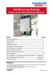
indirect fired power vented air heaters installation and operating ...
indirect fired power vented air heaters installation and operating ...
indirect fired power vented air heaters installation and operating ...

You also want an ePaper? Increase the reach of your titles
YUMPU automatically turns print PDFs into web optimized ePapers that Google loves.
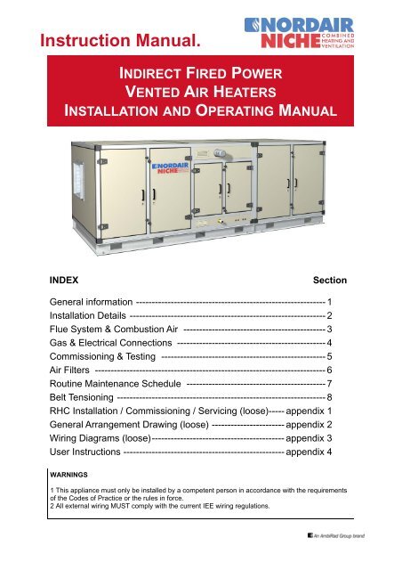
Instruction Manual.<br />
INDIRECT FIRED POWER<br />
VENTED AIR HEATERS<br />
INSTALLATION AND OPERATING MANUAL<br />
INDEX<br />
Section<br />
General information ------------------------------------------------------------ 1<br />
Installation Details -------------------------------------------------------------- 2<br />
Flue System & Combustion Air --------------------------------------------- 3<br />
Gas & Electrical Connections ----------------------------------------------- 4<br />
Commissioning & Testing ---------------------------------------------------- 5<br />
Air Filters ------------------------------------------------------------------------- 6<br />
Routine Maintenance Schedule -------------------------------------------- 7<br />
Belt Tensioning ------------------------------------------------------------------ 8<br />
RHC Installation / Commissioning / Servicing (loose)----- appendix 1<br />
General Arrangement Drawing (loose) ----------------------- appendix 2<br />
Wiring Diagrams (loose)------------------------------------------ appendix 3<br />
User Instructions --------------------------------------------------- appendix 4<br />
WARNINGS<br />
1 This appliance must only be installed by a competent person in accordance with the requirements<br />
of the Codes of Practice or the rules in force.<br />
2 All external wiring MUST comply with the current IEE wiring regulations.
1. General Information.<br />
Before <strong>installation</strong>, check that the<br />
appliance as described on the packaging label is<br />
in accordance with the correct type <strong>and</strong> model as<br />
specified on the data plate <strong>and</strong> complies with the<br />
site requirements.<br />
Please read this document before commencing<br />
<strong>installation</strong>.<br />
Check that the local distribution conditions of<br />
electricity supply, type of gas <strong>and</strong> pressure of the<br />
appliance are compatible.<br />
The <strong>installation</strong> must comply with the<br />
requirements <strong>and</strong> recommendations of British<br />
St<strong>and</strong>ards BS 6230 1991. “Installation of Gas<br />
Fired Forced<br />
Convection Air Heaters for Commercial <strong>and</strong><br />
Industrial Space Heating”.<br />
The <strong>installation</strong> must also be in accordance with<br />
relevant requirements of “The Gas<br />
safety” (Installation <strong>and</strong> use Regulations) <strong>and</strong><br />
(Amendment regulation 1990) <strong>and</strong> the “Building”<br />
<strong>and</strong> “Electrical Regulation” (in GB <strong>and</strong> IEE<br />
Regulations). The requirements of the “Local<br />
Building St<strong>and</strong>ards Office”, the premises<br />
“Insurance” undertaking <strong>and</strong> the “Fire Office”<br />
must also be observed.<br />
corrosive substances <strong>and</strong>/or vapours <strong>and</strong><br />
combustible materials may be present.<br />
When installing outdoor <strong>heaters</strong> care must be<br />
taken to ensure that unauthorised access to the<br />
building cannot be gained via the appliance or its<br />
ductwork system.<br />
This appliance has been tested <strong>and</strong> set<br />
according to the data plate before leaving the<br />
factory.<br />
After <strong>installation</strong> the appliance must be fully<br />
commissioned <strong>and</strong> the settings re-checked.<br />
This appliance incorporates Indirect Gas Fired<br />
Heat Exchange modules. The modules are<br />
purpose designed to be incorporated into <strong>air</strong><br />
heating appliances <strong>and</strong> the modules comply with<br />
CE directives.<br />
This appliance is suitable for operation within a<br />
-10°C to +40°C temperature range.<br />
Unauthorised modification of this appliance or<br />
departure from use in the manner for which it<br />
was intended by the manufacturer or installed in<br />
a manner contrary to these instructions, may<br />
constitute a hazard or jeopardise all warranties.<br />
Deviations should only be carried out after formal<br />
consent has been obtained from the<br />
manufacturer.<br />
Ensure the environment in which the <strong>air</strong> heater<br />
will be installed will not create a hazard i.e,<br />
where excessive (volatile) dust, flammable or
2. Installation<br />
H<strong>and</strong>ling The Equipment<br />
Units with Base Frame<br />
IDF <strong>heaters</strong> supplied with base frames are,<br />
depending on size, supplied in a number of<br />
sections, namely the fan section. The heat<br />
exchanger section <strong>and</strong> mixing box section, each<br />
with a channel base frame, which incorporate<br />
cutouts suitable for lifting purposes.<br />
Each heater should be positioned onto a<br />
prepared flat level concrete base with a minimum<br />
size to suit the footprint of the heater, <strong>and</strong> allow a<br />
minimum 500mm clearance on non-access sides<br />
<strong>and</strong> 2000 on the access side for removal of heat<br />
exchangers.<br />
Each section must be lifted into position using a<br />
suitably sized crane, with lifting bars or lifting<br />
straps threaded through the lifting points. When<br />
using lifting straps sling spreaders must be used<br />
to provide clearance between the appliance <strong>and</strong><br />
the slings.<br />
The mating faces of each section, are fitted with<br />
a sealing tape, <strong>and</strong> predrilled for bolting the<br />
sections together. Each base frame also<br />
incorporates a lug at each corner to bolt the<br />
frames together, levelling screws ensure the<br />
heater is horizontal.<br />
Units with Curb Cap<br />
The unit should be lifted from the bottom base<br />
using the lifting points provided <strong>and</strong> in a manner<br />
that holds it level <strong>and</strong> keeps it from tipping, falling<br />
or twisting. If the unit is severely twisted in<br />
h<strong>and</strong>ling permanent damage may occur. It is the<br />
installers responsibility to ensure that the<br />
h<strong>and</strong>ling of equipment is suitable <strong>and</strong> safe.<br />
All lifting operations must be carried out using<br />
local spreader bars of sufficient width to ensure<br />
that the lifting cables/slings etc, clear the sides of<br />
the unit <strong>and</strong> do not damage the casing.<br />
When installing external weatherproof appliances<br />
ensure that any part of the <strong>installation</strong> that may<br />
be installed outdoors will not jeopardise the<br />
integrity of the premises security.<br />
Ensure that the structural elements which will be<br />
used to support the appliance are adequate to<br />
carry the weight of the appliance <strong>and</strong> its ancillary<br />
components i.e. the ductwork system.<br />
The location where the <strong>air</strong> heater is to be<br />
installed, must provide sufficient space around<br />
the <strong>air</strong> heater for servicing <strong>and</strong> to allow the flue<br />
products to escape freely. A minimum distance<br />
of 1000mm must be maintained on the controls<br />
side of the appliance.<br />
Ensure that the unit is installed in a level plain<br />
<strong>and</strong> that the surface onto which it is installed is<br />
vibration free.<br />
The unit must be fastened securely to any<br />
support frame work.<br />
When siting the appliance <strong>and</strong> unloading,<br />
extreme care must be exercised to ensure that<br />
the slings employed do not damage the casing.<br />
Sling spreaders must be used to provide<br />
clearance between the appliance <strong>and</strong> the<br />
slings.<br />
Duct Connections<br />
Nord<strong>air</strong> Niche IDF <strong>heaters</strong> are designed to be<br />
used in conjunction with <strong>air</strong> intake <strong>and</strong> <strong>air</strong><br />
distribution ducting. A positive seal must be<br />
made between ductwork <strong>and</strong> the connection onto<br />
the appliance. All ductwork must be supported<br />
independently <strong>and</strong> not supported off the heater<br />
casing.<br />
Flexible duct connections to the appliance are<br />
not required as the fan outlet is fitted with a<br />
flexible connection <strong>and</strong> is isolated from the<br />
casing via anti-vibration mounts.<br />
Before placing the unit in position a foam sealant<br />
tape or two beads of sealant should be applied to<br />
the top surface of the roof curb, ensuring good<br />
butt joints at the corners. The unit must be<br />
sealed to the curb to prevent water leakage into<br />
the curb area due to blown rain <strong>and</strong><br />
capillary action.
2. Installation (continued)<br />
Care should be taken when designing ducting<br />
systems especially with regard to the selection of<br />
fittings which will be installed adjacent to the<br />
appliance, abrupt elbows fitted directly on to the<br />
appliance can cause turbulence <strong>and</strong> create<br />
uneven <strong>air</strong> flows across the heat exchanger,<br />
resulting in hot spots <strong>and</strong> nuisance shut down of<br />
the burner due to regional overheating in the<br />
vicinity of the limit stat protection devices.<br />
Unnecessary pressure loss <strong>and</strong> noise generation<br />
may also be caused by badly designed duct<br />
systems.<br />
Ducting should be manufactured from materials<br />
suitable for the purpose also taking into account<br />
the integrity of the building security.<br />
Externally routed ducting should be thermally<br />
insulated <strong>and</strong> protected with a waterproof<br />
membrane.<br />
3. Flue system & combustion <strong>air</strong> supply<br />
Flue systems must comply with national <strong>and</strong><br />
local regulations.<br />
The products combustion must be flued to the<br />
outdoor atmosphere.<br />
Flues should incorporate a disconnect section<br />
adjacent to the appliance to facilitate removal of<br />
the venter assembly for service <strong>and</strong> replacement<br />
purposes. The flue system must be supported<br />
independently <strong>and</strong> not supported by the unit.<br />
Type B Appliances<br />
The <strong>air</strong> heater supplied is as a B type appliance<br />
i.e, <strong>air</strong> for combustion to be taken from within the<br />
space to be heated, then it must be ensured that<br />
an adequate <strong>air</strong> supply for combustion <strong>and</strong><br />
ventilation is provided, in accordance with the<br />
regulations <strong>and</strong> rules in force, in accordance with<br />
BS 6230 1991.<br />
BS 6230 1991 “Specification for Installation of<br />
Gas Fired Forced Convection Air Heaters for<br />
Commercial <strong>and</strong> Industrial space Heating (2nd<br />
family gases)” or BS 5440 “Installation of Flues<br />
<strong>and</strong> Ventilation for Gas Appliances of rated input<br />
not exceeding 60kW (1st, 2nd <strong>and</strong> 3rd family<br />
gases)”.<br />
A horizontal distance between <strong>air</strong> heater <strong>and</strong> flue<br />
terminal must not be in excess of 16meters.<br />
When calculating the total length, the following<br />
equivalent length data must be taken into<br />
account<br />
1 elbow at 45 degrees = 1m<br />
1 elbow at 90 degrees = 1.5m<br />
On long flue runs where condensation may occur<br />
provision should be made to drain the<br />
condensation <strong>and</strong> prevent any condensation<br />
from entering the heat exchanger or venter fan.<br />
If condensation is to be avoided, flues should not<br />
pass through cold areas or not be installed<br />
externally for any great distance.<br />
When mechanical ventilation is used, it should<br />
be mechanically interlocked with either a<br />
mechanical or natural extraction system.<br />
Automatic means of control such as interlocks<br />
must be provided.<br />
The function pressure relief of other ventilation<br />
systems in the zone where the <strong>air</strong> heater is<br />
installed must be taken into account. At no time<br />
should it be possible to create a negative<br />
pressure environment in the zone, this can lead<br />
to a hazardous situation whereby the <strong>air</strong> heater<br />
flue may act as a pressure relief.<br />
The terminal of a vertical flue must extend at<br />
least 1m above a roof surface; flues must not be<br />
located where products of combustion might<br />
enter the building. Terminals must be fitted to<br />
all flue., Wall terminations below 1.8m, above<br />
ground level must be fitted with a terminal guard,<br />
giving a minimal 50mm clearance around the<br />
terminal <strong>and</strong> must not allow a ball of 16mm to<br />
pass through it.<br />
A separate flue system should be taken from<br />
each heat exchanger module within the<br />
appliance.<br />
Refer to appendix 1 for more information
4. Gas & electrical connections<br />
Gas<br />
Connection to gas service may only be carried<br />
out by appropriately qualified persons. The gas<br />
<strong>installation</strong> must comply with the rules in force<br />
using materials appropriate for gas <strong>installation</strong>s.<br />
Check that the gas category is in accordance<br />
with the data described on the <strong>air</strong> heater.<br />
An adequate gas supply sized to provide the<br />
dynamic pressure for the volume required for the<br />
<strong>air</strong> heater/s is essential to maintain the nominal<br />
heat input. Other gas <strong>fired</strong> plant using the same<br />
gas service must also be taken into account.<br />
A 90˚ action, positive isolating ball valve must be<br />
fitted adjacent to the appliance, fitted in a<br />
manner to facilitate access to the burners for<br />
servicing purposes.<br />
Ensure that the gas service has been tested <strong>and</strong><br />
purged in accordance with prescribed practice<br />
prior to commissioning <strong>and</strong> setting the appliance<br />
into service.<br />
Ensure that the gas supply is filtered <strong>and</strong> it is<br />
free of swarf or debris before connecting to the<br />
appliance .<br />
Electrical<br />
The electrical <strong>installation</strong> may only be carried out<br />
by appropriately qualified persons observing the<br />
rules in force.<br />
Check the electrical specification is in<br />
accordance with the specification on the<br />
appliance data plate. A unique appliance wiring<br />
diagram is supplied as a separate document<br />
attached to this one, plus an additional copy<br />
attached to the unit.<br />
The unit must be earthed.<br />
Ensure that <strong>power</strong> will be supplied at all times to<br />
the unit, even when it’s control is switched in the<br />
“HEAT OFF” mode. This is necessary to ensure<br />
that the <strong>air</strong> circulating fan can operate<br />
independently of the heating control.<br />
A separate lockable isolator for each <strong>air</strong> heater<br />
must be provided adjacent to the appliance <strong>and</strong><br />
within the sight of any person working on the<br />
appliance. The isolator must have a contact<br />
separation of at least 3.0mm on all poles. The<br />
isolator should be of the key operable type to<br />
prevent v<strong>and</strong>alism <strong>and</strong> to prevent switching by<br />
others thus placing anyone working on the<br />
appliance at a safety risk.<br />
Where controls are not provided by Nord<strong>air</strong><br />
Niche, then ancillary controls must be installed to<br />
provide timed heat cycles, room comfort<br />
temperature levels, frost protection, override of<br />
<strong>air</strong> circulation etc.<br />
Note When working on the appliance electricity<br />
to the appliance should not be switched OFF<br />
before the room thermostat has been switched<br />
OFF, the gas valve has closed <strong>and</strong> the <strong>air</strong><br />
circulation fan has stopped.<br />
All cable <strong>and</strong> gas service entry points to outdoor<br />
appliances must be sealed to prevent ingress of<br />
water.<br />
If it is necessary to change the rotation of blower<br />
to match the direction indicated on blower<br />
housing then three phase motors can be altered<br />
by switching two phases of the supply to the<br />
motor.<br />
On units fitted with centrifugal forward curved<br />
fans, the speed setting for static pressure<br />
imposed by the <strong>air</strong> distribution system will govern<br />
the motor loading. The units are manufactured<br />
for the duty specified on the data badge (Table<br />
1).<br />
Refer to section Drives general <strong>and</strong> adjustments<br />
for instructions on adjusting the fan speed <strong>and</strong><br />
motor load factors.<br />
After the electrical <strong>installation</strong> has been<br />
completed the appliance should be tested prior<br />
to the commissioning of the gas <strong>fired</strong> heat<br />
exchanger module(s).<br />
NOTE Outdoor commissioning work on Nord<strong>air</strong><br />
Niche appliances should not be undertaken<br />
during wet conditions, a second person should<br />
always be available to provide assistance in the<br />
event of an emergency.<br />
Check to ensure:<br />
• Earth continuity<br />
• Resistance to earth<br />
• Phase supply to correct terminals<br />
• Current rating <strong>and</strong> circuit breaker value
4. Gas & electrical connections (continued)<br />
In addition to the above requirements check to<br />
ensure that the fan performance <strong>and</strong> motor load<br />
factors are correct for the application <strong>and</strong> in<br />
accordance with the appliance data plate.<br />
Drives general <strong>and</strong> adjustments<br />
The drive assembly of Nord<strong>air</strong> Niche Air <strong>heaters</strong><br />
are enclosed within the unit. Alignment <strong>and</strong> belt<br />
tensions should be checked prior to start up, as<br />
indicated in section 8.<br />
It will be necessary to remove the access panels<br />
or open the hinged access door, which is key<br />
lock protected prior to accessing the drive<br />
system.<br />
Before commencing work on the fan assembly:<br />
• Set external controls to off or their<br />
lowest setting<br />
• Ensure that the gas supply to the<br />
<strong>air</strong> heater is turned OFF<br />
• Switch OFF the electricity supply to the <strong>air</strong><br />
heater after the <strong>air</strong> circulating fan has<br />
stopped<br />
• Remove protection panels as necessary<br />
<strong>and</strong> carry out adjustments as appropriate<br />
• Before placing the appliance back into<br />
service or switching the fan on ensure<br />
that all protection access panels are<br />
replaced <strong>and</strong> secured or the access door<br />
is locked <strong>and</strong> the key returned to the end<br />
user<br />
If the external pressure is incorrect or changes<br />
have been made to the system <strong>and</strong> the amount<br />
of adjustment required cannot be obtained by<br />
balancing the system to achieve the motor load<br />
factors required, then it will be necessary to<br />
change a pulley or pulleys <strong>and</strong> possibly the drive<br />
belt(s).<br />
Any rotational speed checks should be carried<br />
out using a stroboscope or an infra red<br />
tachometer.<br />
After adjustment ensure that the motor load<br />
rating is not exceeded.<br />
Be aware that clean or dirty filters will influence<br />
readings.<br />
Units are set at the factory for the fan speed<br />
required to meet the <strong>air</strong>flow <strong>and</strong> external<br />
pressure ordered.<br />
The ductwork system, grilles <strong>and</strong> dampers<br />
should be commissioned <strong>and</strong> balanced to meet<br />
the <strong>air</strong>flow <strong>and</strong> static pressure characteristics of<br />
the appliance.<br />
After balancing ensure that the motor load rating<br />
is not exceeded.
5. Commissioning & testing<br />
The Nord<strong>air</strong> Niche IDF unit is fitted with Indirect<br />
Gas Fired Heat Exchanger(s) as detailed in the<br />
technical data sheet. The attached instructions<br />
(appendix 1) must be read <strong>and</strong> understood prior<br />
to commencing work <strong>and</strong> must be followed for all<br />
commissioning <strong>and</strong> service operations.<br />
Note Outdoor commissioning work on Nord<strong>air</strong><br />
Niche appliances should not be undertaken<br />
during wet conditions, a second person should<br />
always be available to provide assistance in the<br />
event of an emergency.<br />
When <strong>heaters</strong> are used in conjunction with<br />
Smartcom control, ensure that the engineers settings<br />
in the Smartcom are set to suit the application<br />
<strong>and</strong> appropriate sensor. These settings are<br />
fully detailed in the Smartcom manual.<br />
Only persons formally qualified to work on gas<br />
<strong>fired</strong> apparatus may carry out commissioning<br />
<strong>and</strong> testing.<br />
Electrical check<br />
After completion of the <strong>installation</strong> <strong>and</strong> before<br />
switching on the electrical supply to the<br />
appliance, a qualified electrician must carry out a<br />
preliminary check. The following must be<br />
checked:<br />
• Check to ensure that electrical cables/ wiring<br />
do not touch the hot combustion collector box.<br />
• Check that all wiring is connected in<br />
accordance with the appliance circuit diagram.<br />
• Be certain that the correct fuse value <strong>and</strong> cable<br />
size has been provided.<br />
• Check to ensure that the appliance is earthed<br />
by conducting an earth continuity test.<br />
Connect a test meter, one lead to the<br />
appliance earth terminal <strong>and</strong> the other to the<br />
mains incoming earth point at the electrical<br />
isolator. A resistance reading of 1,0 ohm or<br />
less must be indicated. If a higher reading is<br />
obtained, check all cable connections to<br />
ensure adequate security <strong>and</strong> cleanliness. If<br />
problem still exists, it may be necessary to<br />
consult the electricity supply undertaking.<br />
• Carry out a polarity test. Connect one lead of<br />
a suitable AC voltmeter to earth <strong>and</strong> connect<br />
the other lead to the live supply terminal (L) at<br />
the <strong>air</strong> heater. Switch ON the <strong>power</strong> to the <strong>air</strong><br />
heater <strong>and</strong> check for correct voltage. The<br />
same result should be obtained by connecting<br />
the test leads between live <strong>and</strong> neutral.<br />
Connect the voltmeter test leads to N <strong>and</strong> E. A<br />
reading of ± OV should be obtained. If these<br />
tests do not conform with the above, there is a<br />
fault which must be rectified before proceeding<br />
further with the commissioning.<br />
• Ensure that an electrical isolator with two pole<br />
separation with a minimum <strong>air</strong> break between<br />
poles of 3,0 mm has been fitted adjacent to the<br />
<strong>air</strong> heater.<br />
• Check that a suitable thermostat has been<br />
fitted.<br />
• Avoid location in draughty areas or where it<br />
may be influenced by heat sources e.g, the<br />
sun, process plants, etc. The thermostat or<br />
temperature sensor should be mounted on a<br />
vibration free surface <strong>and</strong> mounted about 1.5<br />
metres above floor level. Follow the<br />
thermostat manufacturers fitting instruction.<br />
The thermostat must be suitable for switching<br />
230 volts.<br />
Gas connection<br />
The whole of the gas service <strong>installation</strong><br />
including the meter must be inspected, tested for<br />
soundness <strong>and</strong> purged in.<br />
Caution Never use a flame for checking gas<br />
soundness.<br />
See Appendix 1 for commissioning the heat<br />
Exchangers.<br />
Dampers<br />
Installation<br />
When connecting ductwork to dampers take care<br />
to ensure that damper casing is not twisted by<br />
ductwork <strong>and</strong> that fixings do not penetrate cog<br />
housing of the damper which will affect the<br />
damper mechanism. Ductwork must be<br />
independently supported <strong>and</strong> should not be left<br />
to hang from the damper. Sealing should be in<br />
the form of prestik or a neoprene strip.<br />
Ensure actuator rotation is correct in relation to<br />
blade location to prevent breaking linkages.<br />
Maintenance<br />
At six month intervals disconnect the actuator<br />
<strong>and</strong> check for freedom of movement.
6. Air Filters<br />
COSHH Regulations<br />
The components of filters are inherently safe, but<br />
changing <strong>air</strong> filters could expose operators to a<br />
‘Nuisance Dust’ hazard. We would recommend<br />
that filter changing be carried out by<br />
maintenance personnel wearing simple dust<br />
masks, eye protection, overalls or protective<br />
clothing <strong>and</strong> gloves. Dirty filters should be<br />
sealed into plastic bags for disposal.<br />
Disposable filters<br />
These are supplied in the forms of panel <strong>and</strong> bag<br />
filters <strong>and</strong> are fitted into steel channel runners.<br />
Filters are simply withdrawn through the access<br />
door by sliding the filter along the channel<br />
runner. Filters should generally be replaced<br />
when the pressure drop increases to 0.5”wg<br />
(125pa) above the initial level.<br />
Washable panel filters<br />
Generally as per disposable filters except when<br />
pressure drop indicates dirty filter conditions,<br />
filters should be fully immersed in warm water to<br />
which a mild detergent has been added. Agitate<br />
the filter until clean, rinse <strong>and</strong> allow to dry before<br />
replacing.<br />
High efficiency particle arrestor filters<br />
This type of filter is generally fitted in a front<br />
withdrawal frame. Filters will be held into the<br />
frame by retaining bars which can be removed to<br />
allow access to replace filters.<br />
Carbon filters<br />
Carbon filters normally have an active life of<br />
about twelve months, or more. It is advisable to<br />
remove a sample from the pack to return to the<br />
manufacturer to determine the remaining working<br />
life, preferably after the first six months <strong>and</strong><br />
subsequent six monthly intervals.<br />
Note When replacing all filters ensure filter is<br />
facing correct direction as<br />
Indicated by an <strong>air</strong>flow arrow.<br />
7. Routine maintenance schedule<br />
Monthly 3 Monthly 6 monthly Annually<br />
Fan shaft bearings<br />
X<br />
Motors<br />
Belts & Pulleys<br />
X<br />
X<br />
Heat exchangers<br />
Dampers<br />
X<br />
X<br />
Panel & bag filters<br />
HEPA filters<br />
X<br />
X<br />
Carbon filters<br />
X<br />
External surfaces<br />
X
7. Routine maintenance schedule (continued)<br />
Invalidation of guarantee<br />
The following misuses or maltreatment of Nord<strong>air</strong><br />
Niche equipment will render all guarantees, as<br />
set out on the Conditions of Sales, void.<br />
• Failure to install, set up or put to work any part<br />
of the equipment as specified in Nord<strong>air</strong> Niche<br />
<strong>installation</strong>, operation <strong>and</strong> maintenance<br />
instructions.<br />
• Attempting to operate motors <strong>and</strong> other<br />
electrical equipment with an electrical supply<br />
other than that designated on the motor name<br />
plate, or failing to connect <strong>and</strong> protect such<br />
equipment in accordance with I.E.E<br />
Regulations <strong>and</strong> local by-laws.<br />
• Failure to notify Nord<strong>air</strong> Niche of equipment<br />
damaged on receipt in writing within five days.<br />
• Failure to run equipment within the design<br />
specifications as notified at the time of order.<br />
• Modifications to designed arrangement or<br />
performances without the prior written approval<br />
of Nord<strong>air</strong> Niche.<br />
• Damage caused to equipment on site through<br />
lack of adequate protection from the elements<br />
or misuse by other trades.<br />
• Failure to observe all normally accepted<br />
engineering practices during <strong>installation</strong>,<br />
commissioning <strong>and</strong> subsequent operation of<br />
equipment.<br />
8. Belt tensioning<br />
Belt tensioning procedure using a belt tension indicator
8. Belt tensioning (continued).<br />
• Calculate the deflection distance in mm on a<br />
basis of 16mm per metre of centre distance.<br />
• Set the lower marker ring at the deflection<br />
distance required in mm on the lower scale.<br />
• Set the upper marker ring against the bottom<br />
edge of the tube.<br />
• Place the belt tension indicator on top of the<br />
belt at the centre of the span, <strong>and</strong> apply a force<br />
at right angles to the belt deflecting it to the<br />
point where the lower marker ring is level with<br />
the top of the adjacent belt.<br />
• Read off the force value indicated by the top<br />
edge of the marker ring.<br />
• Compare this force to the kgf value in the table<br />
above.<br />
• If a belt tension indicator is not available, a<br />
spring balance <strong>and</strong> rule will suffice.<br />
Important<br />
After the drive has been running for<br />
approximately 30 minutes, the tension should be<br />
checked <strong>and</strong> re-adjusted to the higher value, is<br />
necessary.
Appendix 4 - User Instructions<br />
Display this near your heater<br />
Important<br />
For safe <strong>and</strong> satisfactory operation, these<br />
instructons should be read <strong>and</strong> fully understood.<br />
General<br />
For continued safe <strong>and</strong> efficient operation, this<br />
heater should be serviced regulary by a<br />
competant service engineer. A full after sales<br />
service is available from Nord<strong>air</strong> Niche . Read<br />
the warranty <strong>and</strong> ensure that the heater is<br />
operated within the terms of the warranty.<br />
Maintain free access to the heater for servicing<br />
<strong>and</strong> do not restrict the <strong>air</strong> supply to the heater.<br />
For your safety<br />
• Ensure that the heater is properly earthed.<br />
• If a gas leak is suspected, turn off the gas<br />
supply <strong>and</strong> contact the gas supplier<br />
immediately.<br />
• DO NOT USE A NAKED FLAME to inspect<br />
gas leaks.<br />
To turn the heater on<br />
1. Turn ‘ON’ the gas supply <strong>and</strong> the electrical<br />
supply to the heater.<br />
2. The time <strong>and</strong> temperature control of the heater<br />
is under the dictates of a time temperature<br />
controller <strong>and</strong> will start automatically.<br />
Note<br />
• On initial start-up, several attempts may be<br />
required to purge the <strong>air</strong> from the<br />
multifuntional control valve.<br />
• If the heater will not ‘start’ on initial start-up,<br />
the ignition controller may be in lockout<br />
position. Depress the reset button.<br />
• After measuring the gas pressure,<br />
ensure the cap is refitted.<br />
Normal <strong>operating</strong> sequence<br />
1. On time signal start, main supply fan starts.<br />
2. Room sensor calling for heat, flue venter<br />
commences a purge period followed by<br />
ignition of the main flame.<br />
3. Below room set point, the burner will fire at<br />
maximum heat input, untill room set point is<br />
achieved. Depending on the type of control<br />
fitted i.e. modulating, high/low or on/off, the<br />
heater input will be reduced accordingly.<br />
4. Room temperature exceeding room set point<br />
will shut down the burner. Main supply fan will<br />
continue to run.<br />
5. On time schedule shutdown the burner <strong>and</strong><br />
main fan is shut down. Outside of the time<br />
schedule frost protection will start the heater. If<br />
the room temperature falls below the frost set<br />
point.<br />
Note<br />
The fan will continue to operate until the heat<br />
exchanger has cooled down.<br />
To shut down the heater for a short period -<br />
Override the time/temperature controller to ‘off’.<br />
To reinstate the heater operation, override the<br />
controller to ‘ON’.<br />
To shut down the heater for an extended<br />
period - Override the time/temperature controller<br />
to ‘OFF’. Isolate the gas <strong>and</strong> electrical supplies.<br />
Operation note<br />
If a momentary interruption to the gas occurs, the<br />
burner will automatically lockout. Burner lockout<br />
must be manually reset.<br />
If the heater continues to lockout after 3 or 4<br />
consecutive attempts at ignition, contact Nord<strong>air</strong><br />
Service Department or your own service<br />
company.<br />
In the event of the heater going into an overheat<br />
condition, wait 30 seconds before resetting. If the<br />
heater continues to go to overheat after 3 or 4<br />
consecutive attempts, contact Nord<strong>air</strong> Niche<br />
Service Department or your own service<br />
company.<br />
Maintenace <strong>and</strong> service<br />
To ensure safe <strong>and</strong> efficient operation, this<br />
heater should be serviced at least annually. It is<br />
strongly recommended that the installing heater<br />
engineer or Nord<strong>air</strong> Niche Service Division be<br />
contacted to provide the necessary service.<br />
Retain on file a copy of the service instructions<br />
for this heater.<br />
To clean the appliance cabinet, wipe the<br />
surfaces with a damp cloth, containing a mild<br />
detergent.
Document reference number GB/NOR/022/1209