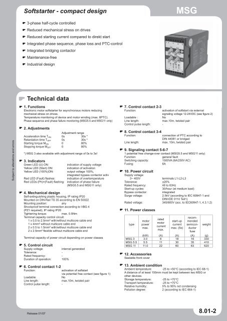
Softstarter - compact design Technical data 8.01-2
Softstarter - compact design Technical data 8.01-2
Softstarter - compact design Technical data 8.01-2

Create successful ePaper yourself
Turn your PDF publications into a flip-book with our unique Google optimized e-Paper software.
<strong>Softstarter</strong> - <strong>compact</strong> <strong>design</strong><br />
MSG<br />
3-phase half-cycle controlled<br />
Reduced mechanical stress on drives<br />
Reduced starting current compared to direkt start<br />
Integrated phase sequence, phase loss and PTC-control<br />
Integrated bridging contactor<br />
Maintenance-free<br />
Industrial <strong>design</strong><br />
Subject to alterations and errors<br />
<strong>Technical</strong> <strong>data</strong><br />
1. Functions<br />
Electronic motor softstarter for asynchronous motors reducing<br />
mechaical stress on drives.<br />
Temperature monitoring of device and motor winding (max. 6PTC).<br />
Phase sequence and phase failure monitoring (MSG5.5 and MSG11 only)<br />
2. Adjustments<br />
Adjustment range<br />
Acceleration time T ON 0s 30s *<br />
Retardation time T OFF 0s 30s *<br />
Starting torque M ON 0 80%<br />
Stopping torque M OFF 0 80%<br />
*) MSG 3 also available with adjustment range of 0s to 3s!<br />
3. Indicators<br />
Green LED (U) ON:<br />
indication of supply voltage<br />
Yellow LED (Start) ON: indication of activation<br />
Yellow LED (100%)ON: output voltage 100%,<br />
integrated bypass contactor activ<br />
Red LED (Fault) flashes: indication of overtemperature<br />
Red LEDs (Ph)+(Fault) flashing: indication of phase failure<br />
(MSG5.5 and MSG11 only)<br />
4. Mechanical <strong>design</strong><br />
Self-extinguishing plastic housing, IP rating IP20<br />
Mounted on DIN-Rail TS 35 according to EN 50022<br />
Mounting position:<br />
any<br />
Shockproof terminal connection according to VBG 4<br />
(PZ1 required), IP rating IP20<br />
Tightening torque:<br />
max. 0.5Nm<br />
Terminal capacity control circuit:<br />
1 x 0.5 to 2.5mm² with/without multicore cable end<br />
1 x 4mm² without multicore cable end<br />
2 x 0.5 to 1.5mm² with/without multicore cable end<br />
2 x 2.5mm² flexible without multicore cable end<br />
Terminal capacity of power circuit depending on power classes<br />
5. Control circuit<br />
Supply voltage:<br />
internal generated<br />
Tolerance: -<br />
Rated frequency: -<br />
Duration of operation: 100%<br />
6. Control contact 1-2<br />
Function:<br />
activation of softstart<br />
via potential free contact (see figure 1)<br />
Loadable:<br />
No<br />
Line length:<br />
max.10m, twisted pair<br />
Control pulse length: -<br />
7. Control contact 2-3<br />
Function:<br />
activation of softstart via external<br />
signaling voltage 12-24VDC (see figure 2)<br />
Loadable :<br />
No<br />
Line length:<br />
max.10m, twisted pair<br />
Control pulse length: -<br />
8. Control contact 3-4<br />
Function:<br />
connection of PTC according to<br />
DIN 44081 or bridged<br />
Line length:<br />
max. 10m, twisted pair<br />
9. Signaling contact 5-6-7<br />
1 potential free change-over contact (MSG5.5 and MSG11 only)<br />
Function:<br />
general fault<br />
Switching capacity: 1500VA (6A/250V AC)<br />
Fusing:<br />
6A<br />
10. Power circuit<br />
Supply voltage:<br />
3~ 400V terminals L1-L2-L3<br />
Tolerance: ±20%<br />
Rated frequency:<br />
48 to 63Hz<br />
Start-up cycles:<br />
30/hour (at medium load)<br />
Bypass contactor:<br />
integrated<br />
Surge voltage:<br />
2.5kV (according to IEC 60947-1 and<br />
DINVDE 0110 Teil1)<br />
Rated voltage: 345/600V (acc. to IEC60947-1, 4.3.1.2)<br />
11. Power classes<br />
type<br />
motor<br />
power<br />
max.<br />
rated<br />
motor<br />
current<br />
max.<br />
start-up<br />
current<br />
max. (5s)<br />
recommended<br />
semiconductor<br />
fuse<br />
weight<br />
(kW) (A) (A) (A) (g)<br />
MSG 3 3.0 6 18 16 330<br />
MSG 5.5 5.5 11 30 35 410<br />
MSG 11 11.0 22 60 63 620<br />
12. Accessories<br />
Sealable front cover<br />
13. Ambient condition<br />
Ambient temperature: -25 to +50°C (according to IEC 68-1)<br />
A distance of at least 100mm must be kept between two MSG or<br />
other devices.<br />
Storage temperature: -25 to +70°C<br />
Transport temperature: -25 to +70°C<br />
Relative humidity:<br />
5% to 95% not condensing<br />
Pollution degree: 2 (according to IEC 664-1)<br />
Release 01/07<br />
<strong>8.01</strong>-2
MSG<br />
Advantages of softstarters<br />
The softstarters series MSG are optimized to reduce mechanical<br />
stress on drives during the start-up and retardation phase. Therefore<br />
the softstarters rise the motor voltage during the<br />
start-up phase within the adjusted time from zero to maximum<br />
supplying voltage. This ensures a steady increase of the motor torque<br />
and protects the machinery from torque shocks.<br />
The slow rise of the motor voltage can be used to reduce the<br />
maximum start-up current. The maximum possible reduction of<br />
current depend on the type of machinery and adjusted softstarter<br />
settings.<br />
Torque<br />
Direct starter<br />
Star-delta starter<br />
<strong>Softstarter</strong><br />
Motor current<br />
Star-delta starter<br />
Direct start<br />
<strong>Softstarter</strong><br />
diagram<br />
Acceleration period<br />
diagram<br />
rpm<br />
Functions<br />
Softstart and softstopp<br />
In the soft startup devices in the MSG series the main circuit is not<br />
controlled by mechanical switching elements but by semiconductor<br />
elements (thyristor modules).<br />
Each phase contains a thyristor and an antiparallel diode which are<br />
partially or wholly conducting during a half-period. The conducting period<br />
is determined by the ignition angle of the thyristor, which in turn is<br />
determined by the internal control electronics. Because of this, the device<br />
can be operated in a star circuit only without a neutral conductor.<br />
Before the soft startup device is activated the MSG checks the supply<br />
system each time for phase failure and phase sequence. If there is no<br />
fault, soft startup is activated and voltage monitoring is deactivated.<br />
The MSG now increases the voltage at the motor linearly with the<br />
startup time to full ac voltage. The time for this voltage ramp can be<br />
set on the TON controller to any value from 0 to 30 seconds. As the<br />
voltage increases, so too does the torque, just rising above the load<br />
moment. The motor therefore starts with slow acceleration.<br />
If the start button is opened, soft rundown is activated (100% LED<br />
goes out). The torque is immediately reduced by the value set on the<br />
MOFF controller (0 to 80%) and uniformly reduced over the set rundown<br />
time (0 to 30s) to zero (Start LED goes out).<br />
Subject to alterations and errors<br />
acceleration ramp<br />
Motor voltage<br />
retardation ramp<br />
Specifying a motor-specific startup moment means that the voltage<br />
(torque) increases rapidly when the soft startup device is activated<br />
until the startup moment set on the MON controller is reached. Only<br />
then does the voltage start increasing slowly for the remaining startup<br />
time until full system voltage is reached (100% LED lights up). In this<br />
way, more effective use is made of the startup time and wear and tear<br />
is kept to a minimum.<br />
LED Start lightens<br />
LED 100% lightens
MSG<br />
Connections<br />
optional semiconductor fuse<br />
(not included)<br />
optional semiconductor fuse<br />
(not included)<br />
Subject to alterations and errors<br />
general<br />
fault<br />
general<br />
fault<br />
*MSG11 only<br />
*MSG11 only
MSG<br />
Dimensions<br />
MSG 3<br />
45mm<br />
MSG 5.5<br />
70mm<br />
Subject to alterations and errors<br />
MSG 11<br />
100mm<br />
www.tele-power-net.com