G2ZMF11 24-240V Timers - Multifunction Technical data
G2ZMF11 24-240V Timers - Multifunction Technical data
G2ZMF11 24-240V Timers - Multifunction Technical data
Create successful ePaper yourself
Turn your PDF publications into a flip-book with our unique Google optimized e-Paper software.
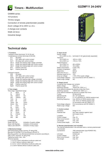
<strong>Timers</strong> - <strong>Multifunction</strong><strong>G2ZMF11</strong> <strong>24</strong>-<strong>24</strong>0VGAMMA series16 functions16 time rangesConnection of remote potentiometer possibleZoom voltage <strong>24</strong> to <strong>24</strong>0V a.c./d.c.2 change-over contactsWidth 22.5mmIndustrial design<strong>Technical</strong> <strong>data</strong>1. Functions1 delayed contact (terminals 15-16-18) and1 instantaneous contact (terminals 25-26-28)E11 ON delayR11 OFF delay with control contactEs11 ON delay with control contactWu11 Single shot leading edge voltage controlledWs11 Single shot leading edge with control contactWa11 Single shot trailing edge with control contactBi11 Flasher pulse firstBp11 Flasher pause first2 delayed contactsE20 ON delayR20 OFF delay with control contactEs20 ON delay with control contactWu20 Single shot leading edge voltage controlledWs20 Single shot leading edge with control contactWa20 Single shot trailing edge with control contactBi20 Flasher pulse firstBp20 Flasher pause first2. Time rangesTime range Adjustment range1s 50ms 1s3s 150ms 3s10s 500ms 10s30s 1500ms 30s1min 3s 1min3min 9s 3min10min 30s 10min30min 90s 30min1h 3min 1h3h 9min 3h10h 30min 10h30h 90min 30h1d 72min 1d3d 216min 3d10d 12h 10d30d 36h 30d3. IndicatorsGreen LED ON:Green LED flashes:Yellow LED ON/OFF:indication of supply voltageindication of time periodindication of relay output4. Mechanical designSelf-extinguishing plastic housing, IP rating IP40Mounted on DIN-Rail TS 35 according to EN 60715Mounting position: any Shockproof terminal connection according toVBG 4 (PZ1 required), IP rating IP20Tightening torque: max. 1NmTerminal capacity:1 x 0.5 to 2.5mm² with/without multicore cable end1 x 4mm² without multicore cable end2 x 0.5 to 1.5mm² with/without multicore cable end2 x 2.5mm² flexible without multicore cable end5. Input circuitSupply voltage:<strong>24</strong> to <strong>24</strong>0V a.c./d.c. terminals A1-A2 (galvanically separated)Tolerance:<strong>24</strong> to <strong>24</strong>0V d.c. -20% to +25%<strong>24</strong> to <strong>24</strong>0V a.c. -15% to +10%Rated frequency:<strong>24</strong> to <strong>24</strong>0V a.c. 48 to 400Hz48 to <strong>24</strong>0V a.c. 16 to 48HzRated consumption: 4.5VA (1W)Duration of operation: 100%Reset time:500msWave form for a.c.: SinusResidual ripple for d.c.: 10%Drop-out voltage: >15% of the supply voltageOvervoltage category: III (in accordance with IEC 60661-1)Rated surge voltage: 4kV6. Output circuit2 potential free change-over contactsRated voltage: 250V a.c.Switching capacity: 750VA (3A / 250V a.c.)If the distance between the devices is less than 5mm.Switching capacity: 1250VA (5A / 250V a.c.)If the distance between the devices is greater than 5mm.Fusing:5A fast actingMechanical life: 20 x 10 6 operationsElectrical Life:2 x 10 5 operations at 1000VA resistive loadSwitching frequency: max. 60/min at 100VA resistive loadmax. 6/min at 1000VA resistive load(in accordance with IEC 60947-5-1)Overvoltage category: III (in accordance with IEC 60664-1)Rated surge voltage: 4kV7. Control contactActivation:Potential free:Loadable:Control voltage:Short circuit current:Line length:Control pulse length:bridge Y1-Y2yes, basic isolation against inputand output circuitnomax. 5Vmax. 1mAmax. 10mmin. 50ms8. Remote potentiometer (not included)The internal potentiometer is de-activated when a remote potentiometeris connected.Connections:1MΩ potentiometer (type RONDO R2),terminals Z1-Y2Line type:twisted pairControl voltage: max. 5VShort circuit current: max. 5μALine length:max. 5mwww.tele-online.com
<strong>G2ZMF11</strong> <strong>24</strong>-<strong>24</strong>0V<strong>Technical</strong> <strong>data</strong>9. AccuracyBase accuracy:±1% (of maximum scale value)using 1MΩ remote potentiometerFrequency response: -Adjustment accuracy: ≤5% (of maximum scale value)using 1MΩ remote potentiometerRepetition accuracy:
<strong>G2ZMF11</strong> <strong>24</strong>-<strong>24</strong>0VFunctionsSingle shot trailing edge with control contact (Wa11)The supply voltage U must be constantly applied to the device (greenLED illuminated). When the control contact Y1-Y2 is closed theinstantaneous contact switches into on-position. When the controlcontact is opened, the instantaneous contact switches into off-position,the delayed contact switches into on-position (yellow LED illuminated)and the set interval t begins (green LED flashes). After the interval thas expired (green LED illuminated), the delayed contact switches intooff-position (yellow LED not illuminated). During the interval, the controlcontact (and the instantaneous contact) can be operated any number oftimes.A further cycle can only be started when the cycle run has beencompleted.OFF delay with control contact (R20)The supply voltage U must be constantly applied to the device (greenLED illuminated). When the control contact Y1-Y2 is closed, the outputrelay R switches into on-position (yellow LED illuminated). If the controlcontact is opened, the set interval t begins (green LED flashes). After theinterval t has expired (green LED illuminated) the output relay switchesinto off-position (yellow LED not illuminated). If the control contactis closed again before the interval t has expired, the interval alreadyexpired is erased and is restarted with the next cycle.ULED UY1-Y2R 15-16-18R 25-26-28t
<strong>G2ZMF11</strong> <strong>24</strong>-<strong>24</strong>0VFunctionsConnectionsSingle shot trailing edge with control contact (Wa20)The supply voltage U must be constantly applied to the device (greenLED illuminated). Closing the control contact Y1-Y2 has no influence onthe condition of the output relay R. When the control contact is opened,the output relay switches into on-position (yellow LED illuminated) andthe set interval t begins (green LED flashes). After the interval t hasexpired (green LED illuminated), the output relay switches into offposition(yellow LED not illuminated). During the interval, the controlcontact can be operated any number of times. A further cycle can onlybe started when the cycle run has been completed.A1Z1SY1Y215213R2U1525LED UY1-Y216 1826 28R 15-16-18R 25-26-28t t25 26 2816 18 A2Flasher pulse first (Bi20)When the supply voltage U is applied, the output relay R switches intoon-position (yellow LED illuminated) and the set interval t begins (greenLED flashes). After the interval t has expired, the output relay switchesinto off-position (yellow LED not illuminated) and the set interval t beginsagain. The output relay is triggered at a ratio of 1:1 until the supplyvoltage is interrupted.DimensionsULED UR 15-16-18R 25-26-28t t t t tFlasher pause first (Bp20)When the supply voltage U is applied, the set interval t begins (greenLED flashes). After the interval t has expired, the output relay R switchesinto on-position (yellow LED illuminated) and the set interval t beginsagain. After the interval t has expired, the output relay switches into offposition(yellow LED not illuminated). The output relay is triggered at aratio of 1:1 until the supply voltage is interrupted.ULED UR 15-16-18R 25-26-28t t t t tRELEASE 2012/05Subject to alterations and errorswww.tele-online.com


