User Guide - IKUSI Multimedia
User Guide - IKUSI Multimedia
User Guide - IKUSI Multimedia

You also want an ePaper? Increase the reach of your titles
YUMPU automatically turns print PDFs into web optimized ePapers that Google loves.
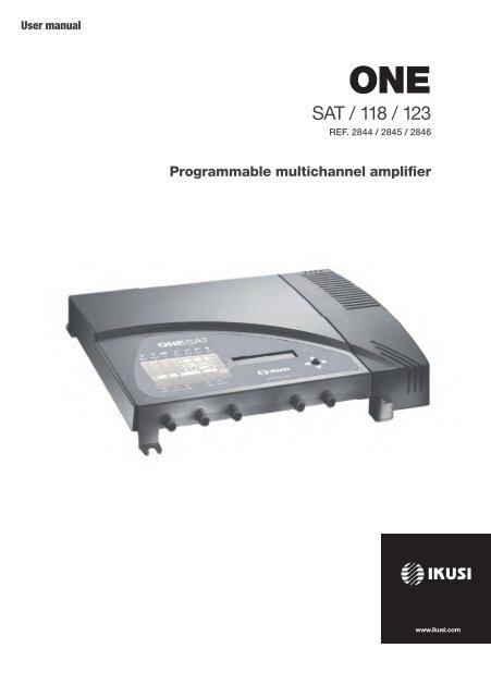
<strong>User</strong> manual<br />
ONE<br />
SAT / 118 / 123<br />
REF. 2844 / 2845 / 2846<br />
Programmable multichannel amplifier
Contents<br />
EN<br />
30 General safety instructions<br />
30 Types of notices<br />
31 Basic safety instructions<br />
32 Introduction<br />
32 General description<br />
32 Main features<br />
34 General equipment use<br />
36 Equipment installation and configuration<br />
36 Installation<br />
36 Power connection<br />
38 Quick menu guide<br />
38 Language selection<br />
38 Manual setting<br />
41 Advanced settings<br />
43 Self-installation<br />
45 Maintenance<br />
45 Equipment care<br />
45 Troubleshooting<br />
46 Technical specifications<br />
46 ONE 118 Model (AFP-201)<br />
47 ONE 123 Model (AFP-211)<br />
48 ONE SAT Model (AFP-292)<br />
50 Technical annex<br />
51 Warranty<br />
51 Equipment recycling<br />
52 CE Certificate<br />
29
General safety instructions<br />
JJ<br />
JJ<br />
JJ<br />
Read all of this user manual carefully before plugging in the equipment.<br />
Always have these instructions to hand during installation.<br />
Follow all of the instructions and safety notices regarding equipment handling.<br />
Types of notices<br />
The meaning of the safety notices used in this manual are described below.<br />
DANGER<br />
DANGER of DEATH OR INJURY<br />
This safety notice indicates a possible danger for the life and health of people.<br />
Not following these instructions may lead to serious consequences to health and<br />
may even cause fatal injuries.<br />
ATTENTION<br />
RISK OF equipmENT damAGE<br />
This safety notice indicates a possible dangerous situation. Not following these<br />
instructions may lead to the equipment being damaged.<br />
Note<br />
This type of notice is a note containing applicable advice and useful information<br />
for optimum use of the equipment.<br />
HANDLING THE INSIDE OF THE EquipmENT IS FORBIDDEN<br />
This notice forbids any work that may affect the working order of the equipment<br />
or its warranty.<br />
DO NOT DISPOSE OF AS URBAN WASTE<br />
This type of notice indicates that the equipment must not be disposed of as<br />
unselected urban waste.<br />
30
General safety instructions / Basic safety instructions<br />
Basic safety instructions<br />
EN<br />
DANGER<br />
DANGER of DEATH OR INJURY<br />
JJ<br />
JJ<br />
Do not install the equipment during an electrical storm. This could lead to<br />
electrostatic discharge from lightning.<br />
Do not open the equipment. This could lead to electric discharge.<br />
ATTENTION<br />
RISK OF equipmENT damAGE<br />
JJ<br />
JJ<br />
JJ<br />
JJ<br />
JJ<br />
The equipment must be appropriately ventilated. Install the equipment in a<br />
dust-free location. Do not place the equipment in a location where the ventilation<br />
slots are covered or blocked. Install the equipment in a location with at<br />
least 20 cm around it free of other objects.<br />
Do not expose the equipment to rain or moisture. Install the equipment in<br />
a dry location with no infiltration or condensation of water. Should a liquid<br />
enter the equipment, disconnect it immediately from the mains.<br />
Keep the equipment away from flammable objects, candles and anything<br />
that may cause a fire.<br />
Connect the equipment to an easily accessible power socket. In the event of<br />
an emergency, it will then be possible to quickly unplug the equipment.<br />
Do not expose the equipment to sources of heat (sun, heating, etc.).<br />
31
Introduction<br />
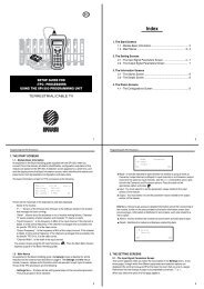
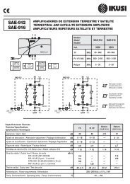
General description<br />
KEY<br />
1 BI-FM input<br />
2 BIII-DAB input<br />
3 VHF-UHF/EXT input **<br />
4 UHF3 input<br />
5 UHF2 input<br />
6 UHF1 input<br />
7 SAT-IF1 input *<br />
8 Mains connector<br />
9 Control button<br />
10 Screen (LCD)<br />
11 Front panel with cluster map<br />
12 SAT-IF2 input with no amplification *<br />
13 Output 2; TV+SAT2 *<br />
14 Output test 2*<br />
15 Output test 1<br />
16 Output 1; TV+SAT1 ***<br />
17 Earthing<br />
* ONE SAT model only<br />
**JJJJJONE SAT and ONE 123 models only<br />
***JJJJIn ONE 123 model and ONE 118 TV only<br />
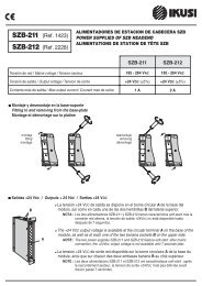
Main features<br />
The ONE 118, ONE 123 and ONE SAT models are programmable amplification headends<br />
designed to selectively filter analogue and digital UHF channels. Suitable for single-family<br />
and collective dwellings, they are the ideal solution for managing signals of different frequencies<br />
and bandwidths.<br />
FM and VHF signals are also amplified. The ONE SAT model also amplifies satellite IF signals.<br />
Individual adjustment of each frequency filter, number of channels and automatic gain<br />
control allows for level equalize of selected channels.<br />
JJ<br />
32<br />
Programming:<br />
FF<br />
FF<br />
FF<br />
Self-installation function.<br />
All settings are automatically memorised.<br />
No external programmer required, programmed directly from the headend.
Introduction / Main features<br />
JJ<br />
JJ<br />
JJ<br />
JJ<br />
JJ<br />
FF<br />
Reprogrammable as many times as required.<br />
10 tuneable UHF filters with the capacity to process 1 to 5 channels each.<br />
Signal processing:<br />
FF<br />
FF<br />
FF<br />
FF<br />
Terrestrial inputs with low noise figure (< 6 dB).<br />
Satellite input with low noise figure (< 9 dB).<br />
Automatic signal level equalisation.<br />
Automatic gain control.<br />
Extra functions:<br />
FF<br />
FF<br />
Internal configuration cloning with transferral to another equipment.<br />
Equipment locking by security code.<br />
Dimensions : 290 mm x 240 mm x 20 mm<br />
Weight : 2 kg<br />
The main features of the ONE 118, ONE 123 and ONE SAT models are described below.<br />
EN<br />
ONE 118 Model<br />
Recommended for small and medium-sized installations made up of 10 UHF filters delivering<br />
an output level of 118 dBμV.<br />
JJ<br />
JJ<br />
Inputs:<br />
FF<br />
FF<br />
FF<br />
FF<br />
5 terrestrial inputs = BI-FM, BIII-DAB, UHF1, UHF2, UHF3.<br />
BI-FM gain = 35 dB.<br />
BIII-DAB gain = 40 dB.<br />
UHF gain = 55 dB.<br />
Outputs:<br />
FF<br />
FF<br />
1 TV output.<br />
1 Test output.<br />
FF<br />
VHF/UHF output level = 118 dBµV. 1<br />
1<br />
IMD3-60 dB, DIN 45004B (see channel reduction table in Technical Annex)<br />
ONE 123 Model<br />
Recommended for small and medium-sized installations made up of 10 UHF filters delivering<br />
an output level of 123 dBμV.<br />
JJ<br />
JJ<br />
Inputs:<br />
FF<br />
FF<br />
FF<br />
FF<br />
FF<br />
6 terrestrial inputs: BI-FM, BIII-DAB, UHF1, UHF2, UHF3, VHF-UHF/EXT<br />
BI-FM gain = 35 dB.<br />
BIII-DAB gain = 40 dB.<br />
UHF gain = 60 dB.<br />
VHF-UHF/EXT gain = 40 dB.<br />
Outputs:<br />
FF<br />
1 TV output.<br />
33
Introduction / General equipment use<br />
FF<br />
1 Test output.<br />
FF<br />
VHF output level = 118 dBµV. 1<br />
FF<br />
UHF output level = 123 dBµV. 1<br />
1<br />
IMD3-60 dB, DIN 45004B (see channel reduction table in Technical Annex)<br />
ONE SAT Model<br />
Recommended for small and medium-sized installations, comprising 10 UHF filters it includes<br />
one satellite input and two mixed television-satellite outputs. CTI compliant.<br />
JJ<br />
JJ<br />
Inputs:<br />
FF<br />
FF<br />
FF<br />
FF<br />
FF<br />
FF<br />
FF<br />
FF<br />
6 terrestrial inputs= BI-FM, BIII-DAB, UHF1, UHF2, UHF3, VHF-UHF/EXT.<br />
2 satellite IF inputs.<br />
BI-FM gain = 30 dB.<br />
BIII-DAB gain = 35 dB.<br />
UHF gain = 55 dB.<br />
VHF-UHF/EXT gain = 35 dB.<br />
SAT1 gain = 40 dB.<br />
SAT2 gain = -1.5 dB.<br />
Outputs:<br />
FF<br />
FF<br />
2 TV+IF outputs.<br />
2 Test outputs.<br />
FF<br />
VHF output level = 113 dBµV. 1<br />
FF<br />
UHF output level = 118 dBµV. 1<br />
FF<br />
FI/SAT output level = 116 dBμV. 2<br />
1<br />
Terrestrial: IMD3-60 dB, DIN 45004B<br />
2<br />
Satellite: IMD3 -35dB, EN50083-3. See channel reduction table in Technical Annex<br />
General equipment use<br />
Interaction with the equipment using the button and the interpreting of the instructions<br />
displayed on the LCD screen are described below. The programme includes a main menu<br />
formed by submenus that can be selected to modify the equipment operating settings.<br />
Instructions displayed on the LCD screen<br />
This symbol is displayed when manual setting is selected. It refers to the<br />
clusters indicated on the panel.<br />
This symbol is displayed in the manual setting menu. Visually locate it on<br />
the LCD screen and see the cluster map on the panel to see which of the<br />
5 equipment clusters is selected.<br />
34
Introduction / General equipment use<br />
This acronym is displayed in the main menu. Select it to go back to the<br />
language selection menu.<br />
EN<br />
▲<br />
▼<br />
This symbol is displayed in manual settings and advanced settings and<br />
visually indicates the possibility of moving vertically.<br />
This symbol is displayed in manual and advanced settings and always<br />
includes a numeric value and visually indicates the gain level.<br />
This icon is displayed when the equipment lock is enabled when the<br />
equipment is switched on and after periods when the equipment is not in<br />
use.<br />
Vertical button movement<br />
In the menus and submenus, move the button up or down to browse<br />
upwards and downwards position by position.<br />
In the settings, move the button up or down to modify values position by<br />
position.<br />
NOTE<br />
Keep the button pressed up or down to browse or to modify<br />
values more quickly.<br />
Horizontal button movement<br />
In the menus, move the button to the left or the right to select and go<br />
back position by position.<br />
In the settings, move the button to the left or the right to browse, select<br />
and go back position by position.<br />
Press button<br />
NOTE<br />
Keep the button pressed to the left or to the right to browse<br />
more quickly.<br />
In the menus, this selects the submenu.<br />
In the submenus, this selects the setting.<br />
In the settings, this selects the parameter value.<br />
35
CFP-7 0<br />
POWER<br />
+12V<br />
5A<br />
+24V<br />
+18V<br />
+13V<br />
+18V<br />
+13V<br />
ITOT (MAX)<br />
60 mA<br />
300 mA<br />
(22 kHz)<br />
300 mA<br />
(22 kHz)<br />
300 mA<br />
300 mA<br />
:700 mA<br />
IKUSUP<br />
CONTROL<br />
RF OUT<br />
SYNC STATUS<br />
+12V<br />
QPSK IN<br />
V LNB<br />
EXT<br />
IKUSUP<br />
CONTROL<br />
QPSK IN<br />
V LNB<br />
SYNC STATUS<br />
+12V<br />
RF OUT<br />
IKUSUP<br />
CONTROL<br />
QPSK IN<br />
V LNB<br />
SYNC STATUS<br />
+12V<br />
RF OUT<br />
LNB<br />
QPSK IN<br />
V<br />
SRF- 1<br />
SRF- 1<br />
SRF- 1<br />
1<br />
DIGITAL SATELLITE<br />
RECEIVER SRF- 1<br />
DIGITAL SATELLITE<br />
DIGITAL SATELLITE<br />
RECEIVER<br />
RECEIVER<br />
IKUSUP<br />
CONTROL<br />
DIGITAL SATELLITE<br />
DIGITAL SATELLITE<br />
RECEIVER<br />
RECEIVER<br />
V/A LOOP<br />
V/A LOOP<br />
V/A LOOP<br />
V/A LOOP<br />
V/A LOOP<br />
GAIN<br />
SYNC<br />
ON<br />
STATUS<br />
+12V<br />
+12V<br />
HPA-120<br />
INPUT<br />
RF OUT<br />
OUTPUT<br />
AUX INPUT<br />
Gain 5 dB<br />
Ref. 4426<br />
BROADBAND AMPLIFIER<br />
47-862 MHz<br />
10<br />
CFP-7 0<br />
ITOT (MAX)<br />
POWER<br />
+12V<br />
5A<br />
+24V<br />
+18V<br />
+13V<br />
+18V<br />
+13V<br />
60 mA<br />
3 0 mA<br />
( 2 kHz)<br />
3 0 mA<br />
( 2 kHz)<br />
3 0 mA<br />
3 0 mA<br />
:7 0 mA<br />
CFP-7 0<br />
ITOT (MAX)<br />
POWER<br />
+12V<br />
5A<br />
+24V<br />
+18V<br />
+13V<br />
+18V<br />
+13V<br />
60 mA<br />
300 mA<br />
(22 kHz)<br />
300 mA<br />
(22 kHz)<br />
300 mA<br />
300 mA<br />
:700 mA<br />
V/A L OP<br />
SRF- 1<br />
DIGITAL SATELLITE<br />
RECEIVER<br />
IKUSUP<br />
CONTROL<br />
QPSK IN<br />
V LNB<br />
SYNC STATUS<br />
+12V<br />
RF OUT<br />
IKUSUP<br />
CONTROL<br />
QPSK IN<br />
V LNB<br />
SYNC STATUS<br />
+12V<br />
V/A L OP V/A L OP<br />
RF OUT<br />
IKUSUP<br />
CONTROL<br />
QPSK IN<br />
V LNB<br />
SYNC STATUS<br />
+12V<br />
RF OUT<br />
QPSK IN<br />
IKUSUP<br />
V LNB<br />
CONTROL<br />
SRF- 1<br />
SRF- 1<br />
SRF- 1<br />
SRF- 1<br />
DIGITAL SATELLITE<br />
DIGITAL RECEIVER<br />
SATELLITE<br />
RECEIVER<br />
V/A L OP<br />
V/A L OP<br />
EXT<br />
DIGITAL SATELLITE<br />
DIGITAL SATELLITE<br />
RECEIVER<br />
RECEIVER<br />
SRF- 1<br />
DIGITAL SATE LITE<br />
RECEIVER<br />
SYNC ON<br />
STATUS<br />
+12V<br />
+12V<br />
INPUT<br />
RF OUT<br />
OUTPUT<br />
AUX INPUT<br />
Gain 5 dB<br />
GAIN<br />
INPUT TEST<br />
OUTPUT TEST<br />
HPA-120<br />
Ref. 426<br />
BROADBAND AMPLIFIER<br />
47-862 MHz<br />
IKUSUP<br />
CONTROL<br />
QPSK IN<br />
V LNB<br />
SYNC STATUS<br />
+12V<br />
V/A L OP V/A L OP<br />
SRF- 1<br />
DIGITAL SATE LITE<br />
RECEIVER<br />
RF OUT<br />
IKUSUP<br />
CONTROL<br />
QPSK IN<br />
V LNB<br />
SYNC STATUS<br />
+12V<br />
SRF- 1<br />
DIGITAL SATE LITE<br />
RECEIVER<br />
RF OUT<br />
10<br />
V/A L OP<br />
IKUSUP<br />
CONTROL<br />
QPSK IN<br />
LNB V<br />
SYNC STATUS<br />
+12V<br />
V/A L OP<br />
SRF- 1<br />
DIGITAL SATE LITE<br />
RECEIVER<br />
RF OUT<br />
IKUSUP<br />
CONTROL<br />
QPSK IN<br />
V LNB<br />
SYNC STATUS<br />
+12V<br />
V/A L OP<br />
SRF- 1<br />
DIGITAL SATE LITE<br />
RECEIVER<br />
RF OUT<br />
OUTPU TEST<br />
ON<br />
+12V<br />
INPUT<br />
AUX INPUT<br />
Gain 5 dB<br />
OUTPUT<br />
HPA-120<br />
Ref. 426<br />
BROADBAND AMPLIFIER<br />
47-862 MHz<br />
GAIN<br />
INPU TEST<br />
Equipment installation and configuration / Installation<br />
Equipment installation and configuration<br />
Only the LCD screen and the button are required to configure the equipment. Follow the<br />
steps below to install the equipment and configure the different parameters.<br />
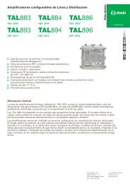
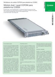
Installation<br />
ATTENTION<br />
RISK OF equipmENT damAGE<br />
Mechanical handling of the equipment<br />
while it is switched on may lead to it<br />
being damaged. Do not plug the equipment<br />
into the mains before or during<br />
installation.<br />
BI-FM BIII-DAB EXT UHF3 UHF2 UHF1 SAT1<br />
2<br />
1) Fit and tighten the bolts and plugs securing<br />
the equipment to the wall.<br />
1<br />
2) Connect the coaxial cable from the aerial to<br />
the equipment.<br />
ONESAT<br />
BI-FM B I-DAB UHF3 UHF2 UHF1 SAT<br />
SAT2 TV+SAT2 TEST TEST TV+SAT1 www.ikusi.com<br />
3) Connect the coaxial cables from the outputs<br />
to the equipment.J<br />
If only one of the 2 outputs is used, terminate<br />
the spare port with a 75Ω loadplug.<br />
3<br />
Test<br />
SAT2<br />
TV+SAT2<br />
Test<br />
TV+SAT1<br />
Power connection<br />
DANGER<br />
DANGER of DEATH OR INJURY<br />
Incorrect equipment power connection<br />
may cause an electric shock. Follow the<br />
steps below for the electrical installation<br />
of the equipment.<br />
2<br />
3<br />
1) Connect the ground cable.<br />
2) Connect the power plug to the equipment<br />
mains connector.<br />
3) Connect the power plug to the mains socket.<br />
ONESAT Ref.2844<br />
BI-FM B I-DAB UHF3 UHF2 UHF1 SAT<br />
SAT2 TV+SAT2 TEST TEST TV+SAT1 www.ikusi.com<br />
1<br />
36
Equipment installation and configuration / Power connection<br />
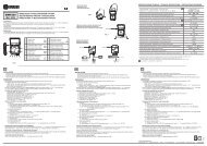
Language<br />
selection<br />
EN<br />
Manual setting<br />
Advanced settings<br />
Self-installation<br />
Filter allocation J<br />
to aerials<br />
(9-0-1)<br />
(7-0-3)<br />
(10-0-0)<br />
(2-7-1)<br />
(2-5-3)<br />
Mast-head amplifier power<br />
Mast-head amplifier power<br />
General J<br />
gain<br />
BI - BII input<br />
BIII-DAB input<br />
UHF output<br />
SAT-IF adjustment<br />
VHF-UHF/EXT J<br />
input<br />
Input preamps<br />
Configuration<br />
cloning<br />
Lock<br />
Equipment<br />
information<br />
Restore J<br />
values<br />
37
Equipment installation and configuration / Quick menu guide<br />
Quick menu guide<br />
Language selection<br />
Note<br />
Over the following pages, the field locating and selection method is primarily<br />
indicated by the “vertical button movement” and “press button” icons. However,<br />
horizontal button movement can be used to locate and select fields, as indicated<br />
in the General equipment use section on Page 8.<br />
Note<br />
The equipment automatically accesses language selection a few sections after<br />
the welcome message is displayed. Language selection can also be accessed by<br />
going back from the main menu.<br />
1) Locate and select the language: ESPAÑOL –<br />
ENGLISH – FRANÇAISE.<br />
2) Access the main menu.<br />
Manual setting<br />
1) In the main menu, locate and select MANUAL.<br />
NOTE<br />
The cluster map on the equipment panel<br />
indicates the cluster related to each submenu.<br />
Filter allocation to aerials<br />
Note<br />
There are five different configurations to<br />
distribute the 10 filters among the 3 aerials.<br />
1) Locate and select the aerial filter configuration<br />
(the aerial distribution is displayed at the top<br />
of the screen and the 10 filters available are<br />
displayed at the bottom):<br />
JJ<br />
For one aerial:<br />
a) Configuration (10 – 0 – 0)<br />
38
Equipment installation and configuration / Manual setting<br />
JJ<br />
For two aerials:<br />
b) Configuration (9 – 0 – 1)<br />
EN<br />
c) Configuration (7 – 0 – 3)<br />
JJ<br />
For three aerials:<br />
d) Configuration (2 – 5 – 3)<br />
e) Configuration (2 – 7 – 1)<br />
Mast-head amplifier power configuration<br />
Note<br />
Only where a mast-head amplifier is fitted<br />
to the aerial.<br />
1) Locate and select the UHF input voltage: VDC,<br />
24 / 12.<br />
2) Locate and select UHF input voltage enabling<br />
(ON) / disabling (OFF):<br />
a) UHF3 input voltage: Ψ3, ON / OFF<br />
b) UHF2 input voltage: Ψ2, ON / OFF<br />
c) UHF1 input voltage: Ψ1, ON / OFF<br />
Filter adjustment<br />
Frequency configuration<br />
1) Locate and select the filter to adjust:<br />
FIL, 1 – 10.<br />
2) Locate and select the filter start channel:<br />
INI, 21 – 69.<br />
3) Locate and select the filter end channel:<br />
FIN, 21 – 69.<br />
39
Equipment installation and configuration / Manual setting<br />
Gain configuration:<br />
Note<br />
If AUT is selected, the equipment adjusts<br />
the gain automatically and completes gain<br />
configuration for the filter selected. If M is<br />
selected, you adjust the gain manually.<br />
1) Locate and select the gain configuration mode<br />
AUT / M.<br />
a) If AUT is selected: self-equalising is<br />
configured.<br />
b) If M is selected: locate and select the gain<br />
level 00 – 30.<br />
General gain adjustment<br />
1) Locate and select the gain submenu:<br />
2) Locate and select the gain level:<br />
a) BI - BII input: BI_BII, 0 - 25<br />
b) BIII - DAB input: BIII_DAB, 0 - 20<br />
c) VHF-UHF/EXT input: VHF_UHF, 0 - 20<br />
d) UHF output: UHF, 0 - 20<br />
40
Equipment installation and configuration / Advanced settings<br />
SAT-IF output adjustment<br />
EN<br />
LNB power configuration<br />
Note<br />
There are 5 different configurations to<br />
select polarisation.<br />
1) Locate and select polarisation:<br />
a) No polarisation: LNB, OFF.<br />
b) 18 V with tones: LNB, 18 V.<br />
c) 18 V without tones: LNB, 18 V.<br />
d) 13 V with tones: LNB, 13 V.<br />
e) 13 V without tones: LNB, 13 V.<br />
Output gain configuration:<br />
1) Locate GA and select level 0 - 20.<br />
Emphasis among high frequencies<br />
Note<br />
If TILT is selected, the equipment applies<br />
9 dB of pre-emphasises.<br />
1) Locate and select TILT to change the level of<br />
pre-emphasis between 0 and 9 dB.<br />
Advanced settings<br />
1) In the main menu, locate and select<br />
ADVANCED.<br />
Input preamps<br />
Note<br />
The gain difference between an enabled and a disabled amplifier is 20 dB. Select<br />
LO to enable an amplifier.<br />
If the gain is set to automatic in filter configuration, the system manages preamp<br />
enabling according to the input level.<br />
1) Locate and select UHF input preamps:<br />
a) UHF3 input: Ψ3, HI / LO.<br />
b) UHF2 input: Ψ2, HI / LO.<br />
c) UHF1 input: Ψ1, HI / LO.<br />
41
Equipment installation and configuration / Advanced settings<br />
Equipment configuration cloning<br />
Note<br />
Cloning begins automatically after the<br />
following steps.<br />
1) Connect two equipments using a coaxial cable<br />
in the Test 1 output of each equipment (see<br />
position (15) in the illustration in the General<br />
Description section on page 6).<br />
2) On the equipment receiving the information:<br />
locate and select MASTER OFF, SLAVE ON.<br />
3) On the equipment sending the information:<br />
locate and select MASTER ON, SLAVE OFF.<br />
Note<br />
The time waited for cloning to be run is 11<br />
seconds. Where cloning cannot be started,<br />
the equipment returns to the higher menu.<br />
Equipment locking<br />
Note<br />
The lock is enabled when the equipment is<br />
re-connected.<br />
1) Enter a sequence of 4 digits (LOCK, 0000).<br />
2) Locate and select LOCK, ON.<br />
Note<br />
To unlock the equipment, enter and select<br />
the 4-digit sequence on the start screen.<br />
To cancel equipment locking, locate and<br />
select LOCK, OFF. If you forget the<br />
4-digit sequence see: Troubleshooting<br />
section on page 19.<br />
42
Equipment installation and configuration / Self-installation<br />
Specific equipment information<br />
EN<br />
Note<br />
Information on the equipment, the programme<br />
version, the manufacturing date,<br />
the number of hours operating, the temperature<br />
and the equipment serial number<br />
are displayed on the screen.<br />
Restore factory values<br />
CAUTION<br />
This function will mean that all previous<br />
configurations will be lost and the factory<br />
values will be restored.<br />
1) Select OK to restore factory values.<br />
Self-installation<br />
Note<br />
The equipment automatically configures the optimum operating frequency and<br />
gain of the UHF filters. The equipment does not automatically configure the<br />
output level of general gains.<br />
1) In the main menu, locate and select<br />
AUTOINSTALL.<br />
a) If NO is selected: you will return to the<br />
main menu.<br />
b) If YES is selected: self-installation will<br />
begin..<br />
43
Equipment installation and configuration / Self-installation<br />
NotE<br />
The equipment displays information on<br />
the status of self-installation. Please<br />
wait a few seconds until it is completed<br />
and AUTOINSTALL COMPLETED is<br />
displayed.<br />
2) Select OK to complete self-installation.<br />
3) To manually configure the output level of general<br />
gains, see: Adjusting general gains section<br />
on Page 14.<br />
4) To review the allocation of filters to aerials, see:<br />
Allocation of filters to aerials section on Page<br />
12.<br />
44
Maintenance<br />
EN<br />
Equipment care<br />
HANDLING THE INSIDE OF THE EquipmENT IS FORBIDDEN<br />
Do not dismantle or try to repair the equipment, its accessories or its components.<br />
This will render the warranty null and void.<br />
JJ<br />
JJ<br />
JJ<br />
JJ<br />
JJ<br />
Do not use the power cable if it is damaged.<br />
To disconnect the power cable, pull carefully on the plug and not the cable.<br />
To clean the panel and equipment connections:<br />
FF<br />
FF<br />
FF<br />
Unplug the equipment.<br />
Clean with a slightly damp, soft cloth.<br />
Allow to dry completely before use.<br />
Do not spill liquid onto the equipment.<br />
Keep ventilation slots free of dust and any foreign bodies.<br />
Troubleshooting<br />
The most frequent problems arising during equipment installation are indicated below. If<br />
you encounter any other type of problem, please contact the equipment sales team.<br />
Problem Possible cause What to do<br />
Forgotten unlock code. - Contact your point of sale.<br />
Nothing displayed on<br />
LCD screen.<br />
The power cable is not connected<br />
properly.J<br />
Check the power cable.<br />
The channels do not<br />
adjust to the programmed<br />
output level.<br />
Lack of signal or unsuitable<br />
channel level.<br />
Check that the channel<br />
programmed in the highest<br />
output channel has a signal and<br />
appropriate level. This is used<br />
as a reference for output level<br />
adjustment.<br />
45
Technical specifications<br />
ONE 118 Model (AFP-201)<br />
Inputs<br />
BI-FM<br />
1<br />
BIII-DAB<br />
1<br />
UHF1 UHF2 UHF3<br />
3<br />
Band width MHz 47-108 174-240 470-862<br />
Input configuration<br />
Number of programmable UHF<br />
filters per input<br />
Gain dB 35 40<br />
- - 10 0 0<br />
- - 9 0 1<br />
- - 7 0 3<br />
- - 2 5 3<br />
- - 2 7 1<br />
35 / 55<br />
(switchable)<br />
Gain adjustment dB 25 20 30<br />
Noise figure dB 10<br />
Selectivity<br />
(± 10 MHz of channel ends)<br />
dB >10<br />
Uncoupling between inputs dB - - >20<br />
AGC tolerance dB - - ±1<br />
Switchable preamp voltage V - - 0-12-24<br />
Maximum preamp current mA - - 100<br />
Output<br />
TV<br />
Output level* dBµV 118 118 118<br />
Output level adjustment dB 20<br />
Return losses dB >10<br />
Test outputs dB -30<br />
Operations<br />
Mains voltage 230 - 240 V~<br />
Consumption<br />
0.25 A / 25 W<br />
Operating temperature -5 to 50 ºC<br />
Mains connector<br />
* IMD3-60dB, DIN 45004B<br />
(See channel reduction table in Technical Annex)<br />
IEC C8<br />
46
Technical specifications / ONE 123 Model (AFP-211)<br />
ONE 123 Model (AFP-211)<br />
EN<br />
Inputs<br />
BI-FM<br />
1<br />
BIII-DAB<br />
1<br />
UHF1 UHF2 UHF3<br />
3<br />
Band width MHz 47-108 174-240 470-862<br />
Input configuration<br />
Number of programmable UHF<br />
filters per input<br />
Gain dB 35 40<br />
EXT (VHF/<br />
UHF)<br />
1<br />
47-240 /<br />
470-862<br />
- - 10 0 0 -<br />
- - 9 0 1 -<br />
- - 7 0 3 -<br />
- - 2 5 3 -<br />
- - 2 7 1 -<br />
40 / 60<br />
(switchable)<br />
Gain adjustment dB 25 20 30 20<br />
Noise figure dB 10<br />
Selectivity (± 10 MHz of channel<br />
ends)<br />
dB >10 -<br />
Uncoupling between inputs dB - - >20 -<br />
AGC tolerance dB - - ±1 -<br />
Switchable preamp voltage V - - 0-12-24 -<br />
Maximum preamp current mA - - 100 -<br />
Output<br />
TV<br />
Output level* dBµV 118 118 123 118/123<br />
Output level adjustment dB 20<br />
Return losses dB >10<br />
Test outputs dB -30<br />
Operations<br />
Mains voltage 230 - 240 V~<br />
Consumption<br />
0.25 A / 25 W<br />
Operating temperature -5 to 50 ºC<br />
Mains connector<br />
* IMD3-60dB, DIN 45004B<br />
(See channel reduction table in Technical Annex)<br />
IEC C8<br />
47
Technical specifications / ONE SAT Model (AFP-292)<br />
ONE SAT Model (AFP-292)<br />
Inputs<br />
BI-FM<br />
1<br />
BIII-DAB<br />
1<br />
UHF1 UHF2 UHF3<br />
3<br />
Band width MHz 47-108 174-240 470-862<br />
Input configuration<br />
Number of programmable<br />
UHF filters per input<br />
Gain dB 30 35<br />
EXT (VHF/<br />
UHF)<br />
1<br />
47-240 /<br />
470-862<br />
SAT-IF<br />
1<br />
950-<br />
2150<br />
FI-SAT<br />
(passive)<br />
1<br />
950-<br />
2150<br />
- - 10 0 0 - - -<br />
- - 9 0 1 - - -<br />
- - 7 0 3 - - -<br />
- - 2 5 3 - - -<br />
- - 2 7 1 - - -<br />
35 / 55<br />
(switchable)<br />
35 40 -1,5<br />
Gain adjustment dB 25 20 30 20 20 -<br />
Noise figure dB 10 >10<br />
Selectivity (± 10 MHz<br />
of channel ends)<br />
Uncoupling between<br />
inputs<br />
dB >10 - - -<br />
dB - - >20 - - -<br />
AGC tolerance dB - - ±1 - - -<br />
Switchable preamp<br />
voltage<br />
Maximum preamp<br />
current<br />
V - - 0-12-24 - 0-13-18 -<br />
mA - - 100 - 300 -<br />
Preamp tones kHz - - - - 0-22 -<br />
Slope adjustment dB - - - - 0-9 -<br />
48
Technical specifications / ONE SAT Model (AFP-292)<br />
Outputs (2)<br />
TV+IF<br />
Output level* dBµV 113 113 118 113 / 118 116 -<br />
Output level<br />
adjustment<br />
dB J JJ20<br />
Return losses dB >10 -<br />
Test outputs (2) dB -30<br />
-<br />
EN<br />
Operations<br />
Mains voltage 230 - 240 V~<br />
Consumption<br />
0.25 A / 25 W<br />
Operating temperature -5 to 50 ºC<br />
Mains connector<br />
IEC C8<br />
* Terrestrial: IMD3-60dB, DIN 45004B ; Satellite: IMD3 -35dB, EN50083-3.<br />
(See channel reduction table in Technical Annex)<br />
49
Technical annex<br />
Output level reduction in broadband amplifiers<br />
BROADBAND TERRESTRIAL TV AMPLIFIERS : The RF output levels specified in this<br />
catalogue for IMD3=-60 dB (DIN 45004 B) are applicable when 2 analog TV channels are<br />
amplified. If, as is usual, more than 2 TV channels are amplified, such levels have to be<br />
reduced according to the following table:<br />
Number of<br />
Channels (n)<br />
Output level<br />
reduction<br />
= 7,5 · log (n-1)<br />
2 3 4 5 6 7 8 9 10 15 20<br />
dB 0 2 3,5 4,5 5 5,5 6 6,5 7 8,5 9,5<br />
FM, DAB AND COFDM SIGNALS : If output levels of the FM, DAB and Digital TV (COFDM) signals are<br />
adjusted 10 dB or more below the levels of the analog TV channels, those signals can be ignored when<br />
calculating the output reduction level. If referred levels are not reduced as indicated, those signals must<br />
be counted as normal channels and the output level de-rated accordingly.<br />
BROADBAND SATELLITE TV OR DIGITAL TERRESTRIAL TV AMPLIFIERS : The RF<br />
output levels specified in this catalogue for IMD3=-35 dB (EN 50083-3) are applicable when<br />
1 FM-, QPSK- or COFDM-modulated TV channel is amplified. For a bigger number of channels,<br />
such levels have to be reduced according to the following table:<br />
Number of<br />
Channels (n)<br />
Output level<br />
reduction<br />
= 10 · log n<br />
2 3 4 5 6 7 8 9 10 15 20<br />
dB 3 4,5 6 7 8 8,5 9 9,5 10 11,5 13<br />
CASCADE REDUCTION : When m same-type broadband amplifiers are laid out in cascade, an additional<br />
reduction of the output level equals 10 · log m must be taken into account for every amplifier.<br />
50
Warranty<br />
Notwithstanding any complaints made to the direct vendor of the product, <strong>IKUSI</strong> offers<br />
equipment users a two-year warranty as of the invoice date, which shall become valid on<br />
presenting the receipt of purchase.<br />
During the warranty period, <strong>IKUSI</strong> is responsible for any faults arising due to material or<br />
manufacturing defects and shall repair the receiver or replace it for another corresponding<br />
to the state of technology at that time. The warranty does not cover any faults or defects<br />
due to misuse or non-fulfilment of the information given in this installation manual.<br />
All complaints other than those indicated are not included in the warranty. More specifically,<br />
the warranty does not cover services provided by the authorised vendor (e.g. installation,<br />
configuration or programme updates) or the repair of any damages or injuries caused to the<br />
client or others as a result of the installation or of receiver operations.<br />
EN<br />
Equipment recycling<br />
Recycling of ELECTRICAL AND ELECTRoNIC equipmENT<br />
(Applicable in the European Union and in European countries with selective<br />
waste collection systems.)<br />
This symbol on your equipment or its packaging indicates that this product<br />
cannot be treated as general domestic waste and must be handed in at the corresponding<br />
point of collection for electric and electronic equipment. By ensuring<br />
this product is disposed of correctly you will help prevent negative consequences<br />
for the environment and human health, which could otherwise be caused by inappropriate<br />
waste handling of this product. Recycling of materials helps preserve<br />
natural resources. For more detailed information on the recycling of this product,<br />
please contact your local council, your nearest collection point or the distributor<br />
from whom you purchased the product.<br />
51
CE Certificate<br />
By reproducing the CE marking, <strong>IKUSI</strong> guarantees equipment compliance with the<br />
corresponding harmonised standards.<br />
EC-Declaration of Conformity<br />
marking<br />
We, Manufacturer<br />
<strong>IKUSI</strong>, Angel Iglesias, S.A.<br />
Paseo Miramón, 170<br />
E-20009 San Sebastián, Spain<br />
declare that the products<br />
Programmable Terrestrial&Satellite Multiband Amplifiers<br />
ONE SAT ,, ONE 118 ,, ONE 123<br />
are in conformity with<br />
E M C<br />
Council Directive 89/336/EEC<br />
(EMC Directive)<br />
Standards to which conformity is declared :<br />
EN 50083-2 :09.95+A1:97<br />
Cabled distribution systems for television, sound and interactive<br />
multimedia signals. Part 2: Electromagnetic compatibility<br />
for equipment.<br />
EN 50083-3 :05.94<br />
Cabled distribution systems for television, sound and interactive<br />
multimedia signals. Part 3: Active coaxial wideband<br />
distribution equipment.<br />
EN 61000-3-2 :04.95<br />
Electromagnetic compatibility (EMC). Part 3: Limits; Section<br />
2: Limits for harmonic current emissions (equipment<br />
input current ≤16 Ampere per phase).<br />
and<br />
L V D<br />
Council Directive 73/23/EEC<br />
(Low Voltage Directive)<br />
Standards to which conformity is declared :<br />
EN 50083-1 :09.93<br />
Cabled Distribution Systems for Television and<br />
Sound Signals. Part 1: Safety Requirements.<br />
EN 60065 :09.93+A11:09.97<br />
Safety requirements for mains operated electronics<br />
and related apparatus for household and similar general<br />
use.<br />
EN 61000-3-3 :01.95<br />
Electromagnetic compatibility (EMC). Part 3: Limits; Section<br />
3: Limitation of voltage fluctuations and flicker in lowvoltage<br />
supply for equipment with rated current ≤16 Ampere.<br />
San Sebastián, September 08/2009<br />
Marco A. Domínguez<br />
R&D Manager<br />
52
Ángel Iglesias, S.A.<br />
Paseo Miramón, 170<br />
20009 San Sebastián, Spain<br />
Tel. +34 943 44 88 00<br />
Fax +34 943 44 88 20<br />
ikusi@ikusi.com<br />
www.ikusi.com<br />
120108B