

CR, CRI, CRN, CRE, CRIE, CRNE - Grundfos Canada
CR, CRI, CRN, CRE, CRIE, CRNE - Grundfos Canada
CR, CRI, CRN, CRE, CRIE, CRNE - Grundfos Canada

You also want an ePaper? Increase the reach of your titles
YUMPU automatically turns print PDFs into web optimized ePapers that Google loves.
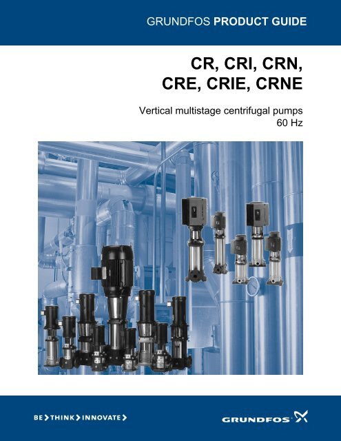
GRUNDFOS PRODUCT GUIDE<br />
<strong>CR</strong>, <strong>CR</strong>I, <strong>CR</strong>N,<br />
<strong>CR</strong>E, <strong>CR</strong>IE, <strong>CR</strong>NE<br />
Vertical multistage centrifugal pumps<br />
60 Hz
Contents<br />
Mission<br />
Product overview<br />
Introduction 4<br />
Product range 6<br />
Applications 8<br />
Pump 9<br />
9<br />
Motor 9<br />
Terminal box positions 10<br />
Ambient temperature 10<br />
Viscosity 10<br />
Product overview for E-pumps<br />
Examples of E-pump applications 11<br />
Control of E-pumps<br />
Control options of E-pumps 12<br />
Control modes for E-pumps 12<br />
Construction<br />
<strong>CR</strong>(E) 1s, 1, 3, 5, 10, 15 and 20 14<br />
<strong>CR</strong>I(E), <strong>CR</strong>N(E) 1s, 1, 3, 5, 10, 15 and 20 14<br />
<strong>CR</strong>(E) 32, 45, 64 and 90 15<br />
<strong>CR</strong>N(E) 32, 45, 64 and 90 15<br />
<strong>CR</strong>(E) 120 and 150 16<br />
<strong>CR</strong>N(E) 120 and 150 16<br />
Type keys and codes<br />
Type keys 17<br />
Codes 17<br />
Operating and inlet pressure<br />
Maximum operating pressure and temperature range 18<br />
Operating range of the shaft seal 19<br />
Maximum inlet pressure 20<br />
<strong>CR</strong>(E), <strong>CR</strong>I(E), <strong>CR</strong>N(E) 5 38<br />
<strong>CR</strong>(E), <strong>CR</strong>I(E), <strong>CR</strong>N(E) 10 42<br />
<strong>CR</strong>(E), <strong>CR</strong>I(E), <strong>CR</strong>N(E) 15 46<br />
<strong>CR</strong>(E), <strong>CR</strong>I(E), <strong>CR</strong>N(E) 20 50<br />
<strong>CR</strong>(E), <strong>CR</strong>N(E) 32 54<br />
<strong>CR</strong>(E), <strong>CR</strong>N(E) 45 57<br />
<strong>CR</strong>(E), <strong>CR</strong>N(E) 64 60<br />
<strong>CR</strong>, <strong>CR</strong>N 90 63<br />
<strong>CR</strong>, <strong>CR</strong>N 120 66<br />
<strong>CR</strong>, <strong>CR</strong>N 150 69<br />
Motor data<br />
Standard motors in the <strong>CR</strong> range 72<br />
TEFC motors 72<br />
ODP motors 73<br />
2 Pole MLE motors 73<br />
Pumped liquids<br />
Pumped liquids 74<br />
List of pumped liquids 74<br />
Accessories<br />
Pipework connection 77<br />
Sensors for <strong>CR</strong>E, <strong>CR</strong>IE, <strong>CR</strong>NE 82<br />
Gauges for <strong>CR</strong>E, <strong>CR</strong>IE, <strong>CR</strong>NE 82<br />
Variants<br />
Lists of variants - on request 83<br />
Motors 83<br />
Connections and other variants 83<br />
Shaft seals 83<br />
Pumps 83<br />
Quotation text<br />
WebCAPS 89<br />
WinCAPS 90<br />
Selection and sizing<br />
Selection of pumps 21<br />
How to read the curve charts 25<br />
Guidelines to performance curves 25<br />
Performance curves/<br />
Technical data<br />
<strong>CR</strong>, <strong>CR</strong>I, <strong>CR</strong>N 1s 26<br />
<strong>CR</strong>(E), <strong>CR</strong>I(E), <strong>CR</strong>N(E) 1 30<br />
<strong>CR</strong>(E), <strong>CR</strong>I(E), <strong>CR</strong>N(E) 3 34<br />
2
Mission<br />
It is our mission — the basis of our existence — to successfully develop, produce and sell high-quality pumps and<br />
pumping systems worldwide, contributing to a better quality of life and a healthy environment<br />
Bjerringbro, Denmark<br />
Fresno, California<br />
Olathe, Kansas<br />
Monterrey, Mexico Allentown, Pennsylvania Oakville, Ontario<br />
• The world's leading pump company<br />
• World's largest manufacturer of circulator pumps<br />
• World headquarters in Denmark<br />
• North American headquarters in Kansas City - Manufacturing in Fresno, California<br />
• 80 companies in 45 countries<br />
• More than 16 million motors and pumps produced annually worldwide<br />
• North American companies operating in USA, <strong>Canada</strong> and Mexico<br />
• Continuous reinvestment in growth and development enables the company to<br />
BE responsible, THINK ahead, and INNOVATE<br />
3
Product overview<br />
<strong>CR</strong>, <strong>CR</strong>I, <strong>CR</strong>N, <strong>CR</strong>E, <strong>CR</strong>IE, <strong>CR</strong>NE<br />
Introduction<br />
This data booklet deals with <strong>CR</strong>, <strong>CR</strong>I and <strong>CR</strong>N as well<br />
as <strong>CR</strong>E, <strong>CR</strong>IE and <strong>CR</strong>NE pumps.<br />
<strong>CR</strong>E, <strong>CR</strong>IE, <strong>CR</strong>NE<br />
<strong>CR</strong>, <strong>CR</strong>I, <strong>CR</strong>N<br />
TM02 7397 3403<br />
Fig. 1 <strong>CR</strong>, <strong>CR</strong>I and <strong>CR</strong>N pumps<br />
<strong>CR</strong>, <strong>CR</strong>I, <strong>CR</strong>N pumps are vertical multistage centrifugal<br />
pumps. The in-line design enables the pump to be<br />
installed in a horizontal one-pipe system where the<br />
suction and discharge ports are in the same horizontal<br />
plane and have the same pipe dimensions. This design<br />
provides a more compact pump design and pipework.<br />
<strong>Grundfos</strong> <strong>CR</strong> pumps come with various pump sizes and<br />
various numbers of stages to provide the flow and the<br />
pressure required.<br />
<strong>CR</strong> pumps are suitable for a variety of applications from<br />
pumping of potable water to pumping of chemicals. The<br />
pumps are therefore used in a wide variety of pumping<br />
systems where the performance and material of the<br />
pump meet specific demands.<br />
The <strong>CR</strong> pumps consist of two main components: the<br />
motor and the pump unit. The motor on a <strong>CR</strong> pump is a<br />
heavy-duty <strong>Grundfos</strong> specified motor.<br />
The pump unit consists of optimized hydraulics, various<br />
types of connections, an outer sleeve, a top and various<br />
other parts.<br />
<strong>CR</strong> pumps are available in various material versions<br />
according to the pumped liquid.<br />
TM02 7698 3803<br />
Fig. 2 <strong>CR</strong>E, <strong>CR</strong>IE and <strong>CR</strong>NE pumps<br />
<strong>CR</strong>E, <strong>CR</strong>IE, <strong>CR</strong>NE pumps are built on the basis of <strong>CR</strong>,<br />
<strong>CR</strong>I, <strong>CR</strong>N pumps.<br />
<strong>CR</strong>E, <strong>CR</strong>IE, <strong>CR</strong>NE pumps belong to the so-called E-<br />
pump family and are referred to as E-pumps.<br />
The difference between the <strong>CR</strong> and the <strong>CR</strong>E pump<br />
range is the motor. <strong>CR</strong>E, <strong>CR</strong>IE, <strong>CR</strong>NE pumps are fitted<br />
with an E-motor, i.e. a motor with built-in frequency<br />
control.<br />
The motor of the <strong>CR</strong>E pump is a <strong>Grundfos</strong> MLE motor.<br />
Frequency control enables continuously variable<br />
control of motor speed, which makes it possible to set<br />
the pump to operation at any duty point. The aim of<br />
continuously variable control of the motor speed is to<br />
adjust the performance to a given requirement.<br />
<strong>CR</strong>E, <strong>CR</strong>IE and <strong>CR</strong>NE pumps are available with an<br />
integrated pressure sensor connected to the frequency<br />
control.<br />
The pump materials are the same as those of the <strong>CR</strong>,<br />
<strong>CR</strong>I, <strong>CR</strong>N pump range.<br />
Selecting a <strong>CR</strong>E pump<br />
Select a <strong>CR</strong>E pump if:<br />
• controlled operation is required, i.e. consumption<br />
fluctuates;<br />
• constant pressure is required,<br />
• communication with the pump is required.<br />
Adaptation of performance through frequencycontrolled<br />
speed control offers obvious advantages:<br />
• Energy savings.<br />
• Increased comfort.<br />
• Control and monitoring of the pump performance.<br />
4
Product overview<br />
<strong>CR</strong>, <strong>CR</strong>I, <strong>CR</strong>N, <strong>CR</strong>E, <strong>CR</strong>IE, <strong>CR</strong>NE<br />
Performance range - <strong>CR</strong>, <strong>CR</strong>I, <strong>CR</strong>N<br />
H<br />
[m]<br />
300<br />
200<br />
H<br />
[ft]<br />
1000<br />
800<br />
600<br />
<strong>CR</strong> 120<br />
<strong>CR</strong>N 120<br />
60 Hz<br />
<strong>CR</strong> 150<br />
<strong>CR</strong>N 150<br />
100<br />
80<br />
60<br />
50<br />
40<br />
30<br />
20<br />
400<br />
300<br />
200<br />
100<br />
80<br />
60<br />
<strong>CR</strong> 1s<br />
<strong>CR</strong>I 1s<br />
<strong>CR</strong>N 1s<br />
<strong>CR</strong> 1<br />
<strong>CR</strong>I 1<br />
<strong>CR</strong>N 1<br />
<strong>CR</strong> 3<br />
<strong>CR</strong>I 3<br />
<strong>CR</strong>N 3<br />
<strong>CR</strong> 5<br />
<strong>CR</strong>I 5<br />
<strong>CR</strong>N 5<br />
<strong>CR</strong> 10<br />
<strong>CR</strong>I 10<br />
<strong>CR</strong>N 10<br />
<strong>CR</strong> 15<br />
<strong>CR</strong>I 15<br />
<strong>CR</strong>N 15<br />
<strong>CR</strong> 32<br />
<strong>CR</strong> 64<br />
<strong>CR</strong>N 32 <strong>CR</strong>N 64<br />
<strong>CR</strong> 20 <strong>CR</strong> 45<br />
<strong>CR</strong> 90<br />
<strong>CR</strong>I 20 <strong>CR</strong>N 45 <strong>CR</strong>N 90<br />
<strong>CR</strong>N 20<br />
10<br />
40<br />
30<br />
20<br />
Eff<br />
[%]<br />
80<br />
60<br />
1 2 4 6 8 10 20 40 60 80 100 200 400 600 800<br />
Q [US GPM]<br />
1 2 3 4 5 6 7 8 10 20 30 40 50 60 80 100 Q [m³/h]<br />
40<br />
20<br />
0<br />
1 2 4 6 8 10 20 40 60 80 100 200 400 600 800<br />
Q [US GPM]<br />
TM02 5518 0209<br />
Performance range - <strong>CR</strong>E, <strong>CR</strong>IE, <strong>CR</strong>NE<br />
H<br />
[m]<br />
300<br />
200<br />
H<br />
[ft]<br />
1000<br />
800<br />
600<br />
<strong>CR</strong>E<br />
60 Hz<br />
100<br />
80<br />
60<br />
50<br />
40<br />
30<br />
20<br />
10<br />
400<br />
300<br />
200<br />
100<br />
80<br />
60<br />
40<br />
30<br />
<strong>CR</strong>E 1s<br />
<strong>CR</strong>IE 1s<br />
<strong>CR</strong>NE 1s<br />
<strong>CR</strong>E 1<br />
<strong>CR</strong>IE 1<br />
<strong>CR</strong>NE 1<br />
<strong>CR</strong>E 3<br />
<strong>CR</strong>IE 3<br />
<strong>CR</strong>NE 3<br />
<strong>CR</strong>E 5<br />
<strong>CR</strong>IE 5<br />
<strong>CR</strong>NE 5<br />
<strong>CR</strong>E 120<br />
<strong>CR</strong>NE 120<br />
<strong>CR</strong>E 150<br />
<strong>CR</strong>NE 150<br />
<strong>CR</strong>E 15<br />
<strong>CR</strong>E 32<br />
<strong>CR</strong>E 64<br />
<strong>CR</strong>IE 15<br />
<strong>CR</strong>NE<br />
<strong>CR</strong>NE<br />
<strong>CR</strong>NE 15<br />
32 64<br />
<strong>CR</strong>E 10<br />
<strong>CR</strong>E 20<br />
<strong>CR</strong>E 45<br />
<strong>CR</strong>E 90<br />
<strong>CR</strong>IE 10<br />
<strong>CR</strong>IE 20<br />
<strong>CR</strong>NE<br />
<strong>CR</strong>NE<br />
<strong>CR</strong>NE 10<br />
<strong>CR</strong>NE 20<br />
45 90<br />
20<br />
2 4 6 8 10 20 40 60 80 100 200 400 600 8001000<br />
Q [US GPM]<br />
Eff<br />
[%]<br />
80<br />
1 2 3 4 5 6 7 8 910<br />
20 30 40 50 60 7080 100 Q [m³/h]<br />
60<br />
40<br />
20<br />
0<br />
2 4 6 8 10 20 40 60 80 100 200 400 600 8001000<br />
Q [US GPM]<br />
TM05 1598 3411<br />
5
Product overview<br />
<strong>CR</strong>, <strong>CR</strong>I, <strong>CR</strong>N, <strong>CR</strong>E, <strong>CR</strong>IE, <strong>CR</strong>NE<br />
Product range<br />
Range <strong>CR</strong> 1s <strong>CR</strong> 1 <strong>CR</strong> 3 <strong>CR</strong> 5 <strong>CR</strong> 10 <strong>CR</strong> 15 <strong>CR</strong> 20<br />
Nominal flow rate [US GPM] 4.5 8.5 15 30 55 95 110<br />
Temperature range [°F] –4 to +250<br />
Temperature range [°F]<br />
– on request<br />
–40 to +356<br />
Max. working pressure [psi] 362 362 362 362 362 362 362<br />
Max. working pressure [psi]<br />
– on request<br />
- 725 725 725 725 725 725<br />
Max. pump efficiency [%] 35 49 59 67 70 72 72<br />
<strong>CR</strong> pumps<br />
<strong>CR</strong>: Flow range [US GPM] 0.5-5.7 1 - 12.8 1.5 - 23.8 3 - 45 5.5 - 70 9.5 - 125 11-155<br />
<strong>CR</strong>: Max. pump pressure (H[ft]) 760 790 790 780 820 800 700<br />
<strong>CR</strong>: Motor power [Hp] .33 - 2 .33 - 3 .33 - 5 .75 - 7.5 .75 - 15 2 - 25 3-25<br />
<strong>CR</strong>E pumps<br />
<strong>CR</strong>E: Flow range [US GPM] - 0 - 12.8 0 - 23.8 0 - 45 0 - 70 0 - 125 0-155<br />
<strong>CR</strong>E: Max. pump pressure (H[ft]) - 790 790 780 820 800 700<br />
<strong>CR</strong>E: Motor power [Hp] - .33 - 3 .33 - 5 .75 - 7.5 .75 - 15 2 - 25 3-25<br />
Version<br />
<strong>CR</strong>, <strong>CR</strong>E:<br />
Cast iron and stainless steel AISI 304<br />
• • • • • • •<br />
<strong>CR</strong>I, <strong>CR</strong>IE:<br />
Stainless steel AISI 304<br />
• • • • • • •<br />
<strong>CR</strong>N, <strong>CR</strong>NE:<br />
Stainless steel AISI 316<br />
• • • • • • •<br />
<strong>CR</strong>T, <strong>CR</strong>TE:<br />
Titanium<br />
- See <strong>CR</strong>T, <strong>CR</strong>TE product guide -<br />
<strong>CR</strong>, <strong>CR</strong>E pipe connection<br />
Oval flange (NPT) 1" 1" 1" 1.25" 2" 2" 2"<br />
Oval flange (NPT) - on request 1.25" 1.25" 1.25" 1" 1.5" - -<br />
ANSI flange size 1.25" 1.25" 1.25" 1.25" 2" 2" 2"<br />
ANSI flange size - on request - - - - - - -<br />
ANSI flange class 250 lb. 250 lb. 250 lb. 250 lb. 250 lb. 250 lb. 250 lb.<br />
<strong>CR</strong>I, <strong>CR</strong>IE pipe connection<br />
Oval flange (NPT) 1" 1" 1" 1.25" 2" 2" 2"<br />
Oval flange (NPT) - on request 1.25" 1.25" 1.25" 1" 1.5" - -<br />
ANSI flange size 1.25" 1.25" 1.25" 1.25" 2" 2" 2"<br />
ANSI flange class 300 lb. 300 lb. 300 lb. 300 lb. 300 lb. 300 lb. 300 lb.<br />
Clamp coupling (NPT) - on request<br />
1",<br />
1.25"<br />
1",<br />
1.25"<br />
Union (NPT ext. Thread) - on request 2" 2" 2" 2" - - -<br />
<strong>CR</strong>N, <strong>CR</strong>NE pipe connection<br />
PJE (Victaulic) 1.25" 1.25" 1.25" 1.25" 2" 2" 2"<br />
PJE (Victaulic) - on request - - - - - - -<br />
ANSI flange size 1.25" 1.25" 1.25" 1.25" 2" 2" 2"<br />
ANSI flange size - on request - - - - - - -<br />
ANSI flange class 300 lb. 300 lb. 300 lb. 300 lb. 300 lb. 300 lb. 300 lb.<br />
Clamp coupling (NPT) - on request<br />
1",<br />
1.25"<br />
1",<br />
1.25"<br />
Union (NPT ext. Thread) - on request 2" 2" 2" 2" - - -<br />
<strong>CR</strong>T pipe connection<br />
PJE coupling (Vitaulic) - 1.25" 1.25" 1.25" 2" 2" -<br />
ANSI flange size - on request - - - - 2" 2" -<br />
• Available<br />
1",<br />
1.25"<br />
1",<br />
1.25"<br />
1",<br />
1.25"<br />
1",<br />
1.25"<br />
1.5",<br />
2"<br />
1.5",<br />
2"<br />
1.5",<br />
2"<br />
1.5",<br />
2"<br />
1.5"<br />
2"<br />
1.5",<br />
2"<br />
6
Product overview<br />
<strong>CR</strong>, <strong>CR</strong>I, <strong>CR</strong>N, <strong>CR</strong>E, <strong>CR</strong>IE, <strong>CR</strong>NE<br />
Range <strong>CR</strong> 32 <strong>CR</strong> 45 <strong>CR</strong> 64 <strong>CR</strong> 90 <strong>CR</strong> 120 <strong>CR</strong> 150<br />
Nominal flow rate [US GPM] 140 220 340 440 610 750<br />
Temperature range [°F] –22 to +250 1) 1) & 2)<br />
–22 to +250<br />
Temperature range [°F]<br />
– on request<br />
–40 to +356 - -<br />
Max. working pressure [psi] 435 435 360 360 360 360<br />
Max. working pressure [psi]<br />
– on request<br />
580 580 580 580 - -<br />
Max. pump efficiency [%] 76 78 79 80 75 73<br />
<strong>CR</strong> pumps<br />
<strong>CR</strong>: Flow range [US GPM] 14-210 22-310 34-450 44-630 61-700 75-790<br />
<strong>CR</strong>: Max. pump pressure (H[ft]) 995 940 565 595 685 570<br />
<strong>CR</strong>: Motor power [Hp] 5-50 7.5-60 10-60 15-60 20-100 25-100<br />
<strong>CR</strong>E pumps<br />
<strong>CR</strong>E: Flow range [US GPM] 0-210 0-310 0-450 0-630 0-700 0-790<br />
<strong>CR</strong>E: Max. pump pressure (H[ft]) 720 490 335 285 140 155<br />
<strong>CR</strong>E: Motor power [Hp] 5-30 7.5-30 10-30 15-30 20-25 25-30<br />
Version<br />
<strong>CR</strong>, <strong>CR</strong>E:<br />
Cast iron and stainless steel AISI 304<br />
• • • • • •<br />
<strong>CR</strong>I, <strong>CR</strong>IE:<br />
Stainless steel AISI 304<br />
- - - - - -<br />
<strong>CR</strong>N, <strong>CR</strong>NE:<br />
Stainless steel AISI 316<br />
• • • • • •<br />
<strong>CR</strong>T, <strong>CR</strong>TE:<br />
Titanium<br />
- - - - - -<br />
<strong>CR</strong>, <strong>CR</strong>E pipe connection<br />
Oval flange (NPT) - - - - - -<br />
Oval flange (NPT) - on request - - - - - -<br />
ANSI flange size 2.5" 3" 4" 4" 5” 3) 5” 3)<br />
ANSI flange size - on request 3" 4" 5" 3) 5" 3) 6” 6”<br />
ANSI flange class<br />
125/<br />
250 lb.<br />
125/<br />
250 lb.<br />
125/<br />
250 lb.<br />
125/<br />
250 lb.<br />
125/<br />
250 lb.<br />
<strong>CR</strong>I, <strong>CR</strong>IE pipe connection<br />
Oval flange (NPT) - - - - - -<br />
Oval flange (NPT) - on request - - - - - -<br />
ANSI flange size - - - - - -<br />
ANSI flange class - - - - - -<br />
Clamp coupling (NPT) - on request - - - - - -<br />
Union (NPT ext. Thread) - on request - - - - - -<br />
<strong>CR</strong>N, <strong>CR</strong>NE pipe connection<br />
PJE (Victaulic) - - - - - -<br />
PJE (Victaulic) - on request 3" 4" 4" 4" 4" 4"<br />
ANSI flange size 2.5" 3" 4" 4" 5” 5”<br />
ANSI flange size - on request 3" - - 5" 6" 6"<br />
ANSI flange class<br />
150/<br />
300 lb.<br />
150/<br />
300 lb.<br />
150/<br />
300 lb.<br />
150/<br />
300 lb.<br />
150/<br />
300 lb.<br />
Clamp coupling (NPT) - on request - - - - - -<br />
Union (NPT ext. Thread) - on request - - - - - -<br />
<strong>CR</strong>T pipe connection<br />
PJE coupling (Vitaulic) - - - - - -<br />
ANSI flange size - on request - - - - - -<br />
• Available<br />
<strong>CR</strong>N 32 to <strong>CR</strong>N 90 with HQQE shaft seal: –40 °F to +250 °F<br />
2) <strong>CR</strong>, <strong>CR</strong>N 120 and 150 with 75 or 100 Hp motors with HBQE shaft seal: 0 °F to +250 °F<br />
3) <strong>CR</strong> 5" flange is not manufactured to ANSI specification. Gasket contact surface is approximately 0.25". <strong>CR</strong> 6" ANSI flange adapter is manufactured to<br />
ANSI B16.5 specification.<br />
125/<br />
250 lb.<br />
150/<br />
300 lb.<br />
7
Product overview<br />
<strong>CR</strong>, <strong>CR</strong>I, <strong>CR</strong>N, <strong>CR</strong>E, <strong>CR</strong>IE, <strong>CR</strong>NE<br />
Applications<br />
Application <strong>CR</strong>, <strong>CR</strong>I <strong>CR</strong>N <strong>CR</strong>E, <strong>CR</strong>NE<br />
Water supply<br />
Filtration and transfer at waterworks • •<br />
Distribution from waterworks • •<br />
Pressure boosting in mains • •<br />
Pressure boosting in high-rise buildings, hotels, etc. • •<br />
Pressure boosting for industrial water supply • •<br />
Industry<br />
Pressure boosting in...<br />
process water systems • • •<br />
washing and cleaning systems • • •<br />
vehicle washing tunnels • •<br />
fire fighting systems<br />
•<br />
Liquid transfer in...<br />
cooling and air-conditioning systems (refrigerants) • •<br />
boiler feed and condensate systems • •<br />
machine tools (cooling lubricants) • • •<br />
aquafarming • <br />
Transfer of...<br />
oils and alcohols • • •<br />
acids and alkalis • •<br />
glycol and coolants • •<br />
Water treatment<br />
Ultra-filtration systems • •<br />
Reverse osmosis systems • •<br />
Softening, ion exchange, demineralizing systems • •<br />
Distillation systems • •<br />
Separators • • •<br />
Swimming pools • •<br />
Irrigation<br />
Field irrigation (flooding) • <br />
Sprinkler irrigation • •<br />
Drip-feed irrigation • <br />
• Recommended version.<br />
Alternative version.<br />
<strong>CR</strong>T, <strong>CR</strong>TE version available. For further information about <strong>CR</strong>T, <strong>CR</strong>TE pumps see, "Pumped liquids" page 74 or related <strong>CR</strong>T, <strong>CR</strong>TE product guide.<br />
8
UR<br />
Product overview<br />
<strong>CR</strong>, <strong>CR</strong>I, <strong>CR</strong>N, <strong>CR</strong>E, <strong>CR</strong>IE, <strong>CR</strong>NE<br />
Pump<br />
The <strong>CR</strong> and <strong>CR</strong>E pump is a non-self-priming, vertical<br />
multistage centrifugal pump. The pumps are available<br />
with a <strong>Grundfos</strong> standard motor (<strong>CR</strong> pumps) or a<br />
frequency-controlled motor (<strong>CR</strong>E pumps).<br />
The pump consists of a base and a pump head. The<br />
chamber stack and the outer sleeve are secured<br />
between the pump head and the base by means of<br />
staybolts. The base has suction and discharge ports on<br />
the same level (in-line).<br />
All pumps are equipped with a maintenance-free<br />
mechanical shaft seal of the cartridge type.<br />
Motor<br />
From 0.5 Hp to 1.5 Hp <strong>Grundfos</strong> offers <strong>CR</strong>E pumps<br />
fitted with single-phase MLE motors (1 x 208-230 V).<br />
From 1.0 Hp to 30 Hp <strong>Grundfos</strong> offers <strong>CR</strong>E pumps fitted<br />
with three-phase MLE motors (3 x 460-480 V). From 1.5<br />
Hp to 7.5 Hp <strong>Grundfos</strong> offers <strong>CR</strong>E pumps fitted with<br />
three-phase MLE motors (3 x 208-230 V).<br />
Electrical data<br />
Mounting<br />
designation NEMA<br />
Insulation<br />
F & B<br />
class<br />
Efficiency<br />
class*<br />
Enclosure<br />
class<br />
60 Hz<br />
Standard<br />
voltages<br />
Energy efficient<br />
Premium efficiency - on request for 15 Hp and above<br />
TEFC - Totally Enclosed Fan Cooled<br />
(<strong>Grundfos</strong> standard)<br />
ODP - Open Drip Proof - on request<br />
1 x 115/208-230 V<br />
3 x 208-230/460 V<br />
3 x 575 V<br />
The motors are rated for:<br />
Baldor ML/MLE MLE<br />
Coupling<br />
Approvals<br />
C<br />
UR<br />
US<br />
LISTED<br />
Impellers<br />
Fig. 3 <strong>CR</strong> pump<br />
<strong>CR</strong> pump with ANSI/NSF 61 listing is available. See UL<br />
file MH26400 or contact <strong>Grundfos</strong>.<br />
Motor<br />
Shaft seal<br />
(Cartridge type)<br />
Base<br />
Pump head<br />
Outer sleeve<br />
Staybolts<br />
Base plate<br />
<strong>Grundfos</strong> standard motors - ML and Baldor® motors<br />
<strong>CR</strong>, <strong>CR</strong>I and <strong>CR</strong>N pumps are fitted with a <strong>Grundfos</strong><br />
specified motor. The motors are all heavy-duty 2-pole,<br />
NEMA C-face motors.<br />
GR5357 - GR3395<br />
* 1 - 10 Hp ML motors are premium efficiency as standard<br />
Optional motors<br />
The <strong>Grundfos</strong> standard range of motors covers a wide<br />
variety of application demands. However, for special<br />
applications or operating conditions, custom-built motor<br />
solutions can be provided.<br />
For special applications or operating conditions,<br />
<strong>Grundfos</strong> offers custom-built motors such as:<br />
• explosion proof motors,<br />
• motors with anti-condensation heating unit,<br />
• low-noise motors,<br />
• premium efficiency motors,<br />
• motors with thermal protection.<br />
Motor protection<br />
Single-phase <strong>Grundfos</strong> specified motors up to 7.5 hp<br />
have a built-in thermal overload switch.<br />
Three-phase motors must be connected to a motor<br />
starter in accordance with local regulations.<br />
Frequency-controlled motors - MLE motors<br />
<strong>CR</strong>E, <strong>CR</strong>IE and <strong>CR</strong>NE pumps are fitted with a totally<br />
enclosed, fan-cooled, 2-pole motor with integrated<br />
variable frequency drive.<br />
9
[%]<br />
P2<br />
80 100 120 140 160 180<br />
60<br />
[°F] T<br />
Product overview<br />
<strong>CR</strong>, <strong>CR</strong>I, <strong>CR</strong>N, <strong>CR</strong>E, <strong>CR</strong>IE, <strong>CR</strong>NE<br />
Terminal box positions<br />
As standard the terminal box is mounted on the suction<br />
side of the pump.<br />
Stellung 6 Position 6 Position Stellung 9 9 Position Stellung 12 12 Stellung 3 Position 3<br />
Standard<br />
TM02 18 05 2001<br />
Fig. 4 Terminal box positions<br />
Ambient temperature<br />
Ambient temperature: Maximum +104 °F.<br />
If the ambient temperature exceeds +104 °F or if the<br />
motor is located 3280 feet above sea level or higher,<br />
the motor output (P2) must be reduced due to the low<br />
cooling effect of the air. In such cases, it may be<br />
necessary to use a motor with a higher output.<br />
2<br />
100<br />
90<br />
70<br />
1 = Baldor motors<br />
2 = <strong>Grundfos</strong> ML motors<br />
1<br />
80<br />
60<br />
50<br />
TM03 4272<br />
3280 7382 11483 15584 ft<br />
Fig. 5 Relationship between motor output (P2) and<br />
ambient temperature<br />
Viscosity<br />
The pumping of liquids with densities or kinematic<br />
viscosities higher than those of water will cause a<br />
considerable pressure drop, a drop in the hydraulic<br />
performance and a rise in the power consumption.<br />
In such situations the pump should be equipped with a<br />
larger motor. If in doubt, contact <strong>Grundfos</strong>.<br />
10
Product overview for E-pumps<br />
<strong>CR</strong>, <strong>CR</strong>I, <strong>CR</strong>N, <strong>CR</strong>E, <strong>CR</strong>IE, <strong>CR</strong>NE<br />
Examples of E-pump applications<br />
<strong>CR</strong>E, <strong>CR</strong>IE and <strong>CR</strong>NE pumps are the ideal solution in<br />
a number of applications characterized by a need for<br />
variable flow at constant pressure. The pumps are<br />
suited for water supply systems and pressure boosting,<br />
but also industrial applications.<br />
Depending on the nature of the application, the pumps<br />
offer energy-savings, increased comfort or improved<br />
processing.<br />
E-pumps in the service of industry<br />
Industry uses a large number of pumps in many<br />
different applications. Demands on pumps in terms of<br />
pump performance and mode of operation make speed<br />
control a must in many applications.<br />
Below are mentioned some of the applications in which<br />
E-pumps are often used.<br />
Constant pressure<br />
• Water supply,<br />
• Washing and cleaning systems,<br />
• Distribution from waterworks,<br />
• Humidifying systems,<br />
• Water treatment systems,<br />
• Process boosting systems, etc.<br />
Example: Within industrial water supply, E-pumps with<br />
integrated pressure sensors are used to ensure a<br />
constant pressure in the piping network. From the<br />
sensor, the E-pump receives inputs about changes of<br />
pressure as a result of changes in the consumption.<br />
The E-pump responds to the input by adjusting the flow<br />
until the pressure is equalized. The constant pressure<br />
is stabilized once more on the basis of a preset<br />
setpoint.<br />
Constant temperature<br />
• Air-conditioning systems at industrial plants,<br />
• Industrial cooling systems,<br />
• Industrial freezing systems,<br />
• Casting and molding tools, etc.<br />
Example: In industrial freezing systems, E-pumps with<br />
temperature sensor increase comfort and lower<br />
operating costs compared with pumps without a<br />
temperature sensor.<br />
An E-pump continuously adapts its performance to the<br />
changing demands reflected in the differences in<br />
temperature of the liquid circulating in the freezing<br />
system. Thus, the lower the demand for cooling, the<br />
smaller the quantity of liquid circulated in the system<br />
and vice versa.<br />
Constant flow<br />
• Steam boiler systems,<br />
• Condensate systems,<br />
• Sprinkler irrigation systems,<br />
• Chemical industry, etc.<br />
Example: In a steam boiler, it is important to be able to<br />
monitor and control pump operation to maintain a<br />
constant level of water in the boiler.<br />
By using an E-pump with level sensor mounted in the<br />
boiler, it is possible to maintain a constant water level.<br />
A constant water level ensures optimum and costefficient<br />
operation as a result of a stabile steam<br />
production.<br />
Dosing<br />
• Chemical industry (i.e. control of pH-values),<br />
• Petrochemical industry,<br />
• Paint industry<br />
• Degreasing systems,<br />
• Bleaching systems, etc.<br />
Example: In the petrochemical industry, E-pumps with<br />
pressure sensors are used as dosing pumps. The E-<br />
pumps help to ensure that the correct mixture ratio is<br />
achieved when more liquids are combined.<br />
E-pumps functioning as dosing pumps improve<br />
processing and offer energy-savings.<br />
E-pumps in commercial building services<br />
Commercial building services use E-pumps to maintain<br />
a constant pressure or a constant temperature based<br />
on a variable flow.<br />
E-pumps are used in applications such as<br />
Constant pressure<br />
• Water supply in high-rise buildings i.e. office<br />
buildings, hotels, etc.<br />
Example: E-pumps with pressure sensors are used for<br />
water supply in high-rise buildings to ensure a constant<br />
pressure even at the highest draw-off point. As the<br />
consumption pattern and by that the pressure changes<br />
during the day, the E-pump continuously adapts its<br />
performance until the pressure is equalized.<br />
Constant temperature<br />
• Air-conditioning systems in hotels, schools,<br />
• Building cooling systems, etc.<br />
Example: E-pumps are an excellent solution in<br />
buildings where constant temperature is essential.<br />
E-pumps keep the temperature constant in airconditioned<br />
high-rise glass buildings, irrespective of the<br />
seasonal fluctuations of the out-door temperature, and<br />
various heat impacts inside the building.<br />
11
Control of E-pumps<br />
<strong>CR</strong>, <strong>CR</strong>I, <strong>CR</strong>N, <strong>CR</strong>E, <strong>CR</strong>IE, <strong>CR</strong>NE<br />
Control options of E-pumps<br />
Communication with <strong>CR</strong>E, <strong>CR</strong>IE, <strong>CR</strong>NE pumps is<br />
possible by means of<br />
• a central management system,<br />
• remote control (<strong>Grundfos</strong> R100) or<br />
• a control panel.<br />
The purpose of controlling an E-pump is to monitor and<br />
control the pressure, temperature, flow and liquid level<br />
of the system.<br />
Remote control<br />
The R100 remote control produced by <strong>Grundfos</strong> is<br />
available as an accessory.<br />
The operator communicates with the E-pump by<br />
pointing the IR-signal transmitter at the control panel of<br />
the E-pump terminal box.<br />
Central management system<br />
Communication with the E-pump is possible even<br />
though the operator is not present near the E-pump.<br />
Communication is enabled by having connected the<br />
E-pump to a central management system allowing the<br />
operator to monitor and change control modes and<br />
setpoint settings of the E-pump.<br />
Fig. 7 R100 remote control<br />
On the R100 display it is possible to monitor and<br />
change control modes and settings of the E-pump.<br />
TM00 4498 2802<br />
Control panel<br />
The control panel of the E-pump terminal box makes it<br />
possible to change the setpoint settings manually.<br />
Light fields<br />
LON-bus connection<br />
G10-LON<br />
Interface<br />
Indicator lights<br />
Fig. 8 Control panel on <strong>CR</strong>E pump<br />
Buttons<br />
TM00 7600 1196<br />
GENIbus connection<br />
E-pump<br />
Fig. 6 Structure of a central management system<br />
TM06592 1103<br />
Control modes for E-pumps<br />
<strong>Grundfos</strong> offers <strong>CR</strong>E, <strong>CR</strong>IE and <strong>CR</strong>NE pumps in two<br />
different variants:<br />
• <strong>CR</strong>E, <strong>CR</strong>IE and <strong>CR</strong>NE with integrated pressure<br />
sensor<br />
• <strong>CR</strong>E, <strong>CR</strong>IE and <strong>CR</strong>NE without sensor.<br />
<strong>CR</strong>E, <strong>CR</strong>IE, <strong>CR</strong>NE with integrated pressure sensor<br />
<strong>CR</strong>E, <strong>CR</strong>IE and <strong>CR</strong>NE pumps with integrated pressure<br />
sensors are suitable for applications where you want to<br />
control the pressure after the pump, irrespective of the<br />
flow. For further information, see the section Examples<br />
of E-pump applications on page 11. Signals of pressure<br />
changes in the piping system are transmitted<br />
continuously from the sensor to the pump.<br />
12
Control of E-pumps<br />
<strong>CR</strong>, <strong>CR</strong>I, <strong>CR</strong>N, <strong>CR</strong>E, <strong>CR</strong>IE, <strong>CR</strong>NE<br />
The pump responds to the signals by adjusting its<br />
performance up or down to compensate for the<br />
pressure difference between the actual and the desired<br />
pressure. As this adjustment is a continuous process, a<br />
constant pressure is maintained in the piping system.<br />
Min.<br />
H<br />
Q<br />
Max.<br />
TM00 9323 4796<br />
Fig. 11 Constant curve mode<br />
<strong>CR</strong>E, <strong>CR</strong>IE and <strong>CR</strong>NE without sensor<br />
<strong>CR</strong>E, <strong>CR</strong>IE and <strong>CR</strong>NE pumps without sensors are<br />
suitable for applications where<br />
Fig. 9 <strong>CR</strong>E, <strong>CR</strong>IE and <strong>CR</strong>NE pumps<br />
A <strong>CR</strong>E, <strong>CR</strong>IE or <strong>CR</strong>NE pump with integrated pressure<br />
sensor facilitates installation and commissioning. <strong>CR</strong>E,<br />
<strong>CR</strong>IE and <strong>CR</strong>NE pumps with integrated pressure<br />
sensor can be set to:<br />
• constant-pressure mode (factory setting) or<br />
• constant-curve mode.<br />
In constant-pressure mode, the pump maintains a<br />
preset pressure after the pump, irrespective of the flow,<br />
see figure below.<br />
TM02 7398 3403<br />
• uncontrolled operation is required<br />
• you want to fit another sensor later in order to<br />
control the flow, temperature, differential<br />
temperature, liquid level, pH value, etc at some<br />
arbitrary point in the system.<br />
<strong>CR</strong>E, <strong>CR</strong>IE and <strong>CR</strong>NE pumps without sensor can be<br />
set to:<br />
• controlled-operation mode or<br />
• uncontrolled-operation mode (factory-setting).<br />
In controlled-operation mode, the pump adjusts its<br />
performance to the desired setpoint, see figure below.<br />
H<br />
H<br />
Hset<br />
Qset<br />
Q<br />
TM02 7264 2803<br />
Q<br />
TM00 9322 4796<br />
Fig. 12 Constant flow mode<br />
In uncontrolled-operation mode, the pump operates<br />
according to the constant curve set, see figure below.<br />
Fig. 10 Constant pressure mode<br />
H<br />
In constant-curve mode, the pump is not controlled. It<br />
can be set to pump according to a preset pump<br />
characteristic within the range from min. curve to max.<br />
curve, see figure below.<br />
Min.<br />
Max.<br />
Q<br />
Fig. 13 Constant curve mode<br />
<strong>CR</strong>E, <strong>CR</strong>IE and <strong>CR</strong>NE pumps can be fitted with sensor<br />
types listed on page 82.<br />
TM00 9323 4796<br />
13
Construction<br />
<strong>CR</strong>, <strong>CR</strong>I, <strong>CR</strong>N, <strong>CR</strong>E, <strong>CR</strong>IE, <strong>CR</strong>NE<br />
<strong>CR</strong>(E) 1s, 1, 3, 5, 10, 15 and 20<br />
<strong>CR</strong>I(E), <strong>CR</strong>N(E) 1s, 1, 3, 5, 10, 15 and 20<br />
TM02 1198 0601 - GR7377 - GR7379<br />
TM02 1808 2001 - GR7373 - GR7375<br />
Sectional drawing<br />
Sectional drawing<br />
1<br />
1<br />
5<br />
9<br />
8<br />
3<br />
4<br />
10<br />
6<br />
7<br />
TM02 1194 1403<br />
3<br />
2 10<br />
4<br />
6<br />
5<br />
7<br />
8<br />
9<br />
12<br />
11<br />
TM03 2156 3805<br />
Materials: <strong>CR</strong>(E)<br />
Pos. Designation Materials AISI/ASTM<br />
1 Pump head Cast iron A 48-30 B<br />
3 Shaft Stainless steel<br />
1) <strong>CR</strong>(E) 1s, 1, 3, 5<br />
2) <strong>CR</strong>(E) 10, 15, 20<br />
3) Stainless steel available on request.<br />
4) CF 8M is cast equivalent of AISI 316 stainless steel.<br />
5) <strong>CR</strong>I(E)/<strong>CR</strong>N(E) 1s, 1, 3, 5<br />
6) <strong>CR</strong>N(E) 10, 15, 20<br />
7) <strong>CR</strong>I(E) 10, 15, 20<br />
AISI 316 1)<br />
AISI 431 2)<br />
4 Impeller Stainless steel AISI 304<br />
5 Chamber Stainless steel AISI 304<br />
6 Outer sleeve Stainless steel AISI 304<br />
7<br />
O-ring for outer<br />
sleeve<br />
EPDM or FKM<br />
8 Base Cast iron A 48-30 B<br />
9 Neck ring PTFE<br />
10 Shaft seal Cartridge type<br />
Bearing rings Silicon carbide<br />
Rubber parts EPDM or FKM<br />
12 FJG flange Cast iron A 48-30 B<br />
Materials: <strong>CR</strong>I(E), <strong>CR</strong>N(E)<br />
Pos. Designation Materials AISI/ASTM<br />
1 Pump head Cast iron 3) A 48-30 B<br />
2 Pump head cover Stainless steel CF 8M 4)<br />
3 Shaft Stainless steel<br />
AISI 316 5)<br />
AISI 329 6)<br />
AISI 431 7)<br />
8 Base Stainless steel CF 8M 4)<br />
9 Neck ring PTFE<br />
10 Shaft seal Cartridge type<br />
11 Base plate Cast iron 3) A 48-30 B<br />
Bearing rings<br />
Silicon carbide<br />
Rubber parts<br />
EPDM or FKM<br />
<strong>CR</strong>I(E)<br />
4 Impeller Stainless steel AISI 304<br />
5 Chamber Stainless steel AISI 304<br />
6 Outer sleeve Stainless steel AISI 304<br />
7 O-ring for outer sleeve EPDM or FKM<br />
12 FGJ flange ring Ductile iron 3) A 65-45-12<br />
Oval flange Stainless steel AISI 316<br />
<strong>CR</strong>N(E)<br />
4 Impeller Stainless steel AISI 316<br />
5 Chamber Stainless steel AISI 316<br />
6 Outer sleeve Stainless steel AISI 316<br />
7 O-ring for outer sleeve EPDM or FKM<br />
12 FGJ flange ring Ductile iron 3) A 65-45-12<br />
14
Construction<br />
<strong>CR</strong>, <strong>CR</strong>I, <strong>CR</strong>N, <strong>CR</strong>E, <strong>CR</strong>IE, <strong>CR</strong>NE<br />
<strong>CR</strong>(E) 32, 45, 64 and 90<br />
<strong>CR</strong>N(E) 32, 45, 64 and 90<br />
TM01 2150 1298<br />
TM02 7399 3403<br />
Sectional drawing<br />
Sectional drawing<br />
2<br />
2<br />
3<br />
3<br />
10<br />
10<br />
4<br />
1<br />
4<br />
1<br />
6<br />
11<br />
7<br />
8<br />
13<br />
5<br />
9<br />
12<br />
TM03 2157 3805<br />
6<br />
11<br />
7<br />
8<br />
14<br />
5<br />
9<br />
12<br />
13<br />
TM03 2158 3805<br />
Materials: <strong>CR</strong>(E)<br />
Materials: <strong>CR</strong>N(E)<br />
Pos. Designation Materials AISI/ASTM<br />
1 Pump head Ductile iron A 65-45-12<br />
2 Motor stool Cast iron A 48-30 B<br />
3 Shaft Stainless steel AISI 431<br />
4 Impeller Stainless steel AISI 304<br />
5 Chamber Stainless steel AISI 304<br />
6 Outer sleeve Stainless steel AISI 304<br />
7<br />
O-ring for outer<br />
sleeve<br />
EPDM or FKM<br />
8 Base Ductile iron A 65-45-12<br />
9 Neck ring Acoflon 215<br />
10 Shaft seal Cartridge type<br />
11 Bearing ring Bronze<br />
12<br />
Bottom bearing<br />
ring<br />
Tungsten carbide/<br />
Tungsten carbide<br />
13 Flange ring Ductile iron 2) A 65-45-12<br />
Rubber parts EPDM or FKM<br />
Pos. Designation Materials AISI/ASTM<br />
1 Pump head Stainless steel CF 8M 1)<br />
2 Motor stool Cast iron A 48-30 B<br />
3 Shaft Stainless steel SAF 2205<br />
4 Impeller Stainless steel AISI 316<br />
5 Chamber Stainless steel AISI 316<br />
6 Outer sleeve Stainless steel AISI 316<br />
7<br />
O-ring for outer<br />
sleeve<br />
EPDM or FKM<br />
8 Base Stainless steel CF 8M 1)<br />
9 Neck ring Acoflon 215<br />
10 Shaft seal Cartridge type<br />
11 Bearing ring<br />
Carbon-graphite filled<br />
PTFE<br />
12<br />
Bottom<br />
bearing ring<br />
Tungsten carbide/<br />
Tungsten carbide<br />
13 Base plate Ductile iron 2) A 65-45-12<br />
14 Flange ring Ductile iron 2) A 65-45-12<br />
Rubber parts EPDM or FKM<br />
1)<br />
CF 8M is cast equivalent of AISI 316 stainless steel.<br />
2)<br />
Stainless steel available on request.<br />
15
Construction<br />
<strong>CR</strong>, <strong>CR</strong>I, <strong>CR</strong>N, <strong>CR</strong>E, <strong>CR</strong>IE, <strong>CR</strong>NE<br />
<strong>CR</strong>(E) 120 and 150<br />
<strong>CR</strong>N(E) 120 and 150<br />
GrA3731<br />
Sectional drawing<br />
Sectional drawing<br />
TM03 8835 2607<br />
TM03 8836 2607<br />
GrA3732 - GrA3735<br />
Materials: <strong>CR</strong>(E)<br />
Pos. Designation Materials AISI/ASTM<br />
1 Pump head Ductile iron<br />
2<br />
1)<br />
22 mm shaft, 15-60 Hp. 32 mm shaft, 75-100 Hp.<br />
A 536<br />
65-45-12<br />
Motor stool (15-60 Hp) Cast iron A48-30 B<br />
Motor stool (75-100 Hp)<br />
Ductile iron<br />
A 536<br />
65-45-12<br />
3 Shaft Stainless steel AISI 431<br />
4 Impeller Stainless steel AISI 304<br />
5 Chamber Stainless steel AISI 304<br />
6 Outer sleeve Stainless steel AISI 316<br />
7 O-ring for outer sleeve EPDM or FKM<br />
8 Base Ductile iron<br />
9 Base plate Ductile iron<br />
10 Neck ring PTFE<br />
11 Shaft seal 1) Cartridge type<br />
12 Support bearing PTFE<br />
13 Bearing rings Silicone carbide<br />
Rubber parts<br />
EPDM or FKM<br />
A 536<br />
65-45-12<br />
A 536<br />
65-45-12<br />
Materials: <strong>CR</strong>N(E)<br />
Pos. Designation Materials AISI/ASTM<br />
1 Pump head Stainless steel A 351 CF 8M<br />
Motor stool (15-60 Hp) Cast iron A48-30 B<br />
2<br />
A 536<br />
Motor stool (75-100 Hp) Ductile iron<br />
65-45-12<br />
3 Shaft Stainless steel SAF 2205<br />
4 Impeller Stainless steel AISI 316<br />
5 Chamber Stainless steel AISI 316<br />
6 Outer sleeve Stainless steel AISI 316<br />
7 O-ring for outer sleeve EPDM or FKM<br />
8 Base Stainless steel A 351 CF 8M<br />
9 Base plate Ductile iron 1) A 536<br />
65-45-12<br />
10 Neck ring PTFE<br />
11 Shaft seal 2) Cartridge type<br />
12 Support bearing PTFE<br />
13 Bearing rings Silicone carbide<br />
14 Base plate Ductile iron 1) A 536<br />
65-45-12<br />
Rubber parts<br />
EPDM or FKM<br />
1) Stainless steel available on request.<br />
2)<br />
22 mm shaft, 15-60 Hp. 32 mm shaft, 75-100 Hp.<br />
16
Type keys and codes<br />
<strong>CR</strong>, <strong>CR</strong>I, <strong>CR</strong>N, <strong>CR</strong>E, <strong>CR</strong>IE, <strong>CR</strong>NE<br />
Type keys<br />
<strong>CR</strong>(E), <strong>CR</strong>I(E), <strong>CR</strong>N(E)<br />
Example<br />
Type range:<br />
<strong>CR</strong>, <strong>CR</strong>I, <strong>CR</strong>N<br />
Pump with integrated<br />
frequency control<br />
Nominal flow rate [m 3 /h]<br />
All impellers with reduced diameter<br />
(applies only to <strong>CR</strong>, <strong>CR</strong>I, <strong>CR</strong>N 1s)<br />
Number of impellers<br />
Number of reduced diameter impellers<br />
(<strong>CR</strong>(E), <strong>CR</strong>N(E) 32, 45, 64, 90, 120, and 150)<br />
Code for pump version<br />
Code for pipe connection<br />
Code for materials<br />
Code for rubber parts<br />
Code for shaft seal<br />
Codes<br />
<strong>CR</strong> E 32 (s) -4 -2 -A -G -G -E - HQQE<br />
Example<br />
A -G -A -E -H QQ E<br />
Pump version<br />
A Basic version 1)<br />
B Oversize motor<br />
E Certificate/approval<br />
<strong>CR</strong> pump for high temperatures<br />
F<br />
(air-cooled top assembly)<br />
H Horizontal version<br />
High-pressure pump with high speed MLE<br />
HS<br />
motor<br />
I Different pressure rating<br />
J Pump with different max speed<br />
K Pump with low NPSH<br />
M Magnetic drive<br />
N Fitted with sensor<br />
P Undersize motor<br />
R Horizontal version with bearing bracket<br />
SF High pressure pump<br />
Over size motor<br />
T<br />
(two flange sizes bigger)<br />
U NEMA version 1)<br />
X Special version<br />
Pipe connection<br />
A Oval flange<br />
B NPT thread<br />
CA FlexiClamp (<strong>CR</strong>I(E), <strong>CR</strong>N(E) 1, 3, 5, 10, 15, 20)<br />
CX Triclamp (<strong>CR</strong>I(E), <strong>CR</strong>N(E) 1, 3, 5, 10, 15, 20)<br />
F DIN flange<br />
G ANSI flange<br />
J JIS flange<br />
N Changed diameter of ports<br />
P PJE coupling<br />
X Special version<br />
Example<br />
A -G -A -E -H QQ E<br />
Materials<br />
A Basic version<br />
D Carbon-graphite filled PTFE (bearings)<br />
G Wetted parts AISI 316<br />
All parts stainless steel, wetted parts AISI<br />
GI<br />
316<br />
I Wetted parts AISI 304<br />
All parts stainless steel, wetted parts AISI<br />
II<br />
304<br />
K Bronze (bearings)<br />
S SiC bearings + PTFE neck rings<br />
X Special version<br />
Code for rubber parts<br />
E EPDM<br />
F FXM<br />
K FFKM<br />
V FKM<br />
Shaft seal<br />
A O-ring seal with fixed driver<br />
B Rubber bellows seal<br />
E Cartridge seal with O-ring<br />
H Balanced cartridge seal with O-ring<br />
K Metal bellows cartridge seal<br />
O Double seal, back-to-back<br />
P Double seal, tandem<br />
X Special version<br />
B Carbon, synthetic resin-impregnated<br />
H Cemented tungsten carbide, embedded (hybrid)<br />
Q Silicon carbide<br />
U Cemented tungsten carbide<br />
X Other ceramics<br />
E EPDM<br />
F FXM<br />
K FFKM<br />
V FKM<br />
1) In August 2003 the NEMA version pump code was discontinued for all<br />
material numbers created by <strong>Grundfos</strong> manufacturing companies in<br />
North America. The NEMA version pump code will still remain in effect<br />
for existing material numbers. NEMA version pumps built in North<br />
America after this change will have either an A or U as the pump version<br />
code depending on the date the material number was created.<br />
17
Operating and inlet<br />
pressure<br />
<strong>CR</strong>, <strong>CR</strong>I, <strong>CR</strong>N, <strong>CR</strong>E, <strong>CR</strong>IE, <strong>CR</strong>NE<br />
Maximum operating pressure and temperature range<br />
Oval flange<br />
ANSI, Clamp, PJE<br />
TM02 1379 1101<br />
TM02 8835 0904<br />
Max. permissible<br />
operating<br />
pressure<br />
Liquid temperature<br />
range<br />
Max.<br />
permissible<br />
operating pressure<br />
Liquid temperature<br />
range<br />
<strong>CR</strong>, <strong>CR</strong>I, <strong>CR</strong>N 1s 232 [psi] –4 °F to +248 °F 362 [psi] –4 °F to +248 °F<br />
<strong>CR</strong>(E), <strong>CR</strong>I(E), <strong>CR</strong>N(E) 1 232 [psi] –4 °F to +248 °F 362 [psi] –4 °F to +248 °F<br />
<strong>CR</strong>(E), <strong>CR</strong>I(E), <strong>CR</strong>N(E) 3 232 [psi] –4 °F to +248 °F 362 [psi] –4 °F to +248 °F<br />
<strong>CR</strong>(E), <strong>CR</strong>I(E), <strong>CR</strong>N(E) 5 232 [psi] –4 °F to +248 °F 362 [psi] –4 °F to +248 °F<br />
<strong>CR</strong>(E) 10-1 › <strong>CR</strong>(E) 10-6 145 [psi] –4 °F to +248 °F - -<br />
<strong>CR</strong>I(E), <strong>CR</strong>N(E) 10-1 › <strong>CR</strong>I(E), <strong>CR</strong>N(E) 10-10 232 [psi] –4 °F to +248 °F - -<br />
<strong>CR</strong>(E), <strong>CR</strong>I(E) 10-1 › <strong>CR</strong>(E), <strong>CR</strong>I(E) 10-10 - - 232 [psi] –4 °F to +248 °F<br />
<strong>CR</strong>(E), <strong>CR</strong>I(E) 10-12 › <strong>CR</strong>(E), <strong>CR</strong>I(E) 10-17 - - 362 [psi] –4 °F to +248 °F<br />
<strong>CR</strong>N(E) 10 - - - 362 [psi] –4 °F to +248 °F<br />
<strong>CR</strong>(E) 15-1 › <strong>CR</strong>(E) 15-5 145 [psi] –4 °F to +248 °F - -<br />
<strong>CR</strong>I(E), <strong>CR</strong>N(E) 15-1 › <strong>CR</strong>I(E), <strong>CR</strong>N(E) 15-8 232 [psi] –4 °F to +248 °F - -<br />
<strong>CR</strong>(E), <strong>CR</strong>I(E) 15-1 › <strong>CR</strong>(E), <strong>CR</strong>I(E) 15-8 - - 232 [psi] –4 °F to +248 °F<br />
<strong>CR</strong>(E), <strong>CR</strong>I(E) 15-9 › <strong>CR</strong>(E), <strong>CR</strong>I(E) 15-12 - - 362 [psi] –4 °F to +248 °F<br />
<strong>CR</strong>N(E) 15 - - 362 [psi] –4 °F to +248 °F<br />
<strong>CR</strong>(E) 20-1 › <strong>CR</strong>(E) 20-5 145 [psi] –4 °F to +248 °F - -<br />
<strong>CR</strong>I(E), <strong>CR</strong>N(E) 20-1 › <strong>CR</strong>I(E), <strong>CR</strong>N(E) 20-7 232 [psi] –4 °F to +248 °F - -<br />
<strong>CR</strong>(E), <strong>CR</strong>I(E) 20-1 › <strong>CR</strong>(E), <strong>CR</strong>I(E) 20-7 - - 232 [psi] –4 °F to +248 °F<br />
<strong>CR</strong>(E), <strong>CR</strong>I(E) 20-8 › <strong>CR</strong>(E), <strong>CR</strong>I(E) 20-10 - - 362 [psi] –4 °F to +248 °F<br />
<strong>CR</strong>N(E) 20 - - 362 [psi] –4 °F to +248 °F<br />
<strong>CR</strong>(E), <strong>CR</strong>N(E) 32-1-1 › <strong>CR</strong>(E), <strong>CR</strong>N(E) 32-5 - - 232 [psi] –22 °F to +248 °F<br />
<strong>CR</strong>, <strong>CR</strong>N 32-6-2 › <strong>CR</strong>, <strong>CR</strong>N 32-11-2 - - 435 [psi] –22 °F to +248 °F<br />
<strong>CR</strong>(E), <strong>CR</strong>N(E) 45-1-1 › <strong>CR</strong>(E), <strong>CR</strong>N(E) 45-4-2 - - 232 [psi] –22 °F to +248 °F<br />
<strong>CR</strong>(E), <strong>CR</strong>N(E) 45-4-1 › <strong>CR</strong>, <strong>CR</strong>N 45-8-1 - - 435 [psi] –22 °F to +248 °F<br />
<strong>CR</strong>(E), <strong>CR</strong>N(E) 64-1-1 › <strong>CR</strong>(E), <strong>CR</strong>N(E) 64-3 - - 232 [psi] –22 °F to +248 °F<br />
<strong>CR</strong>(E), <strong>CR</strong>N(E) 64-4-2 › <strong>CR</strong>(E), <strong>CR</strong>N(E) 64-5-2 - - 435 [psi] –22 °F to +248 °F<br />
<strong>CR</strong>(E), <strong>CR</strong>N(E) 90-1-1 › <strong>CR</strong>(E), <strong>CR</strong>N(E) 90-3 - - 232 [psi] –22 °F to +248 °F<br />
<strong>CR</strong>(E), <strong>CR</strong>N(E) 90-4-2 › <strong>CR</strong>(E), <strong>CR</strong>N(E) 90-4-1 - - 435 [psi] –22 °F to +248 °F<br />
<strong>CR</strong>(E), <strong>CR</strong>N(E) 120-1-1 › <strong>CR</strong>(E), <strong>CR</strong>N(E) 120-5-1 - - 435 [psi] –22 °F to +248 °F<br />
<strong>CR</strong>(E), <strong>CR</strong>N(E) 150-1-1 › <strong>CR</strong>(E), <strong>CR</strong>N(E) 150-4-1 - - 435[psi] –22 °F to +248 °F<br />
18
Operating and inlet<br />
pressure<br />
<strong>CR</strong>, <strong>CR</strong>I, <strong>CR</strong>N, <strong>CR</strong>E, <strong>CR</strong>IE, <strong>CR</strong>NE<br />
Operating range of the shaft seal<br />
The operating range of the shaft seal depends on<br />
operating pressure, pump type, type of shaft seal and<br />
liquid temperature. The following curves apply to clean<br />
water and water with anti-freeze liquids. For selecting<br />
the right shaft seal, see List of pumped liquids on<br />
page 74.<br />
<strong>CR</strong> 1s - <strong>CR</strong> 20<br />
p<br />
[bar]<br />
25<br />
20<br />
15<br />
10<br />
5<br />
0<br />
p<br />
[psi]<br />
400<br />
300<br />
200<br />
100<br />
HQQE<br />
0<br />
-40 0 40 80 120 160 200 240 t [°F]<br />
Fig. 14 Operating range of standard shaft seals for<br />
<strong>CR</strong> 1s - <strong>CR</strong> 20<br />
<strong>CR</strong> 32 - <strong>CR</strong> 150 (3.0-60 Hp)<br />
p<br />
[bar]<br />
30<br />
25<br />
20<br />
15<br />
10<br />
5<br />
0<br />
HQQE<br />
HQQV<br />
HQQE<br />
p<br />
[psi]<br />
500<br />
HUBE / HUBV HUBE<br />
400<br />
300<br />
KUHE / KUHV<br />
200<br />
KUBE / KUBV KUBE<br />
KUUE / KUUV<br />
100<br />
0<br />
-40 0 40 80 120 160 200 240 t [°F]<br />
KUUE<br />
KUUE<br />
KUUV<br />
-40 -20 0 20 40 60 80 100 t [°C]<br />
TM02 7537 3703<br />
TM02 7873 0604<br />
Shaft<br />
seal<br />
Description<br />
HQQE<br />
O-ring (cartridge) (balanced seal),<br />
SiC/SiC, EPDM<br />
HBQE<br />
O-ring (cartridge) (balanced seal),<br />
Carbon/SiC, EPDM<br />
HQQV<br />
O-ring (cartridge) (balanced seal),<br />
SiC/SiC, FKM<br />
HUBE<br />
O-ring (cartridge) (balanced seal),<br />
TC/carbon, EPDM<br />
HUBV<br />
O-ring (cartridge) (balanced seal),<br />
TC/carbon, FKM<br />
KUBE<br />
Bellows, metal (cartridge),<br />
TC/carbon, EPDM<br />
KUBV<br />
Bellows, metal (cartridge),<br />
TC/carbon, FKM<br />
Bellows, metal (cartridge),<br />
KUHE TC/Carbon with embedded TC,<br />
EPDM<br />
Bellows, metal (cartridge),<br />
KUHV TC/Carbon with embedded TC,<br />
FKM<br />
KUUE<br />
Bellows, metal (cartridge), TC/TC,<br />
EPDM<br />
KUUV<br />
Bellows, metal (cartridge), TC/TC,<br />
FKM<br />
Note: TC= tungsten carbide<br />
See section Lists of variants - on request on page 83,<br />
in case of extreme temperatures:<br />
• low temperatures down to –40 °F or<br />
• high temperatures up to +356 °F.<br />
Max. temp.<br />
range [ °F]<br />
–22 °F to +248 °F<br />
+32 °F to +248 °F<br />
–4 °F to +194 °F<br />
+32 °F to +248 °F<br />
+32 °F to +194 °F<br />
+32 °F to +248 °F<br />
+32 °F to +194 °F<br />
+32 °F to +194 °F<br />
+32 °F to +194 °F<br />
–22 °F to +194 °F<br />
–4 °F to +194 °F<br />
Fig. 15 Operating range of standard shaft seals for<br />
<strong>CR</strong> 32 - <strong>CR</strong> 150 (3.0-60 Hp)<br />
<strong>CR</strong> 120 - <strong>CR</strong> 150 (75-100 Hp)<br />
p<br />
[psi]<br />
400<br />
300<br />
200<br />
100<br />
HQQE<br />
HQQV<br />
HQQE<br />
HQQE/V<br />
HBQE/V<br />
HQQE<br />
HBQE<br />
0<br />
-80 -40 0 40 80 120 160 200 240 t [°F]<br />
TM04 4415<br />
Fig. 16 Operating range of standard shaft seals for<br />
<strong>CR</strong> 120 - <strong>CR</strong> 150 (75-100 Hp)<br />
19
Operating and inlet<br />
pressure<br />
<strong>CR</strong>, <strong>CR</strong>I, <strong>CR</strong>N, <strong>CR</strong>E, <strong>CR</strong>IE, <strong>CR</strong>NE<br />
Maximum inlet pressure<br />
The following table shows the maximum permissible<br />
inlet pressure. However, the current inlet pressure + the<br />
pressure against a closed valve must always be lower<br />
than the maximum permissible operating pressure.<br />
If the maximum permissible operating pressure is<br />
exceeded, the conical bearing in the motor may be<br />
damaged and the life of the shaft seal reduced.<br />
<strong>CR</strong>, <strong>CR</strong>I, <strong>CR</strong>N 1s<br />
1s-2 › 1s-27 145 [psi]<br />
<strong>CR</strong>(E), <strong>CR</strong>I(E), <strong>CR</strong>N(E) 1<br />
1-2 › 1-25<br />
1-27<br />
<strong>CR</strong>(E), <strong>CR</strong>I(E), <strong>CR</strong>N(E) 3<br />
3-2 › 3-15<br />
3-17 › 3-25<br />
<strong>CR</strong>(E), <strong>CR</strong>I(E), <strong>CR</strong>N(E) 5<br />
5-2 › 5-9<br />
5-10 › 5-24<br />
<strong>CR</strong>(E), <strong>CR</strong>I(E), <strong>CR</strong>N(E) 10<br />
10-1 › 10-5<br />
10-6 › 10-17<br />
<strong>CR</strong>(E), <strong>CR</strong>I(E), <strong>CR</strong>N(E) 15<br />
15-1 › 15-2<br />
15-3 › 15-12<br />
<strong>CR</strong>(E), <strong>CR</strong>I(E), <strong>CR</strong>N(E) 20<br />
20-1<br />
20-2 › 20-10<br />
<strong>CR</strong>(E), <strong>CR</strong>N(E) 32<br />
32-1-1 › 32-2<br />
32-3-2 › 32-6<br />
32-7-2 › 32-11-2<br />
<strong>CR</strong>(E), <strong>CR</strong>N(E) 45<br />
45-1-1 › 45-1<br />
45-2-2 › 45-3<br />
45-4-2 › 45-8-1<br />
<strong>CR</strong>(E), <strong>CR</strong>N(E) 64<br />
64-1-1<br />
64-1 › 64-2-1<br />
64-2 › 64-5-2<br />
<strong>CR</strong>(E), <strong>CR</strong>N(E) 90<br />
90-1-1 › 90-2-2<br />
90-2-1 › 90-4-1<br />
<strong>CR</strong>(E), <strong>CR</strong>N(E) 120<br />
120-1<br />
120-2-2 › 120-3<br />
120-4-2 › 120-5-1<br />
<strong>CR</strong>(E), <strong>CR</strong>N(E) 150<br />
150-1-1<br />
150-1 › 150-2<br />
150-3-2 › 150-4-1<br />
145 [psi]<br />
218 [psi]<br />
145 [psi]<br />
218 [psi]<br />
145 [psi]<br />
218 [psi]<br />
116 [psi]<br />
145 [psi]<br />
116 [psi]<br />
145 [psi]<br />
116 [psi]<br />
145 [psi]<br />
58 [psi]<br />
145 [psi]<br />
218 [psi]<br />
58 [psi]<br />
145 [psi]<br />
218 [psi]<br />
58 [psi]<br />
145 [psi]<br />
218 [psi]<br />
145 [psi]<br />
218 [psi]<br />
145 [psi]<br />
218 [psi]<br />
290 [psi]<br />
145 [psi]<br />
218 [psi]<br />
290 [psi]<br />
Example of operating and inlet pressures<br />
The values for operating and inlet pressures shown in<br />
the tables must not be considered individually but must<br />
always be compared, see the following examples:<br />
Example 1:<br />
The following pump type has been selected:<br />
<strong>CR</strong> 3-10 A-A-A<br />
Max. operating pressure: 232 psi<br />
Max. inlet pressure: 145 psi<br />
Discharge pressure against a closed valve: 139.2 psi,<br />
see page 34.<br />
This pump is not allowed to start at an inlet pressure of<br />
145 psi, but at an inlet pressure of 232.0 – 139.2 =<br />
92.8 psi.<br />
Example 2:<br />
The following pump has been selected:<br />
<strong>CR</strong> 10-2 A-GJ-A<br />
Max. operating pressure: 232 psi<br />
Max. inlet pressure: 116 psi<br />
Discharge pressure against a closed valve:<br />
42 psi (97 ft), see page 42.<br />
This pump is allowed to start at an inlet pressure of<br />
116 psi, as the discharge pressure is only 42 psi, which<br />
results in an operating pressure of 116 + 42 = 158 psi.<br />
On the contrary, the max. operating pressure of this<br />
pump is limited to 158 psi, as a higher operating<br />
pressure will require an inlet pressure of more than<br />
116 psi.<br />
In case the inlet or operating pressure exceeds the<br />
pressure permitted, see section Lists of variants - on<br />
request on page 83.<br />
20
Selection and sizing<br />
<strong>CR</strong>, <strong>CR</strong>I, <strong>CR</strong>N, <strong>CR</strong>E, <strong>CR</strong>IE, <strong>CR</strong>NE<br />
Selection of pumps<br />
Selection of pumps should be based on<br />
• The duty point of the pump (see section 1)<br />
• Sizing data such as pressure loss as a result of<br />
height differences, friction loss in the pipework,<br />
pump efficiency etc. (see section 2)<br />
• Pump materials (see section 3)<br />
• Pump connections (see section 4)<br />
• Shaft seal (see section 5).<br />
1. Duty point of the pump<br />
From a duty point it is possible to select a pump on the<br />
basis of the curve charts in the section Performance<br />
curves/Technical data starting on page 26.<br />
H<br />
[m]<br />
300<br />
280<br />
260<br />
240<br />
220<br />
200<br />
180<br />
160<br />
140<br />
120<br />
100<br />
80<br />
60<br />
40<br />
20<br />
0<br />
H<br />
[ft]<br />
1000<br />
-11-2<br />
<strong>CR</strong>(E) 32<br />
950<br />
-10<br />
<strong>CR</strong>N(E) 3 2<br />
900<br />
-10-2<br />
2-pole, 60 Hz<br />
850<br />
-9<br />
800<br />
-9-2<br />
750<br />
-8<br />
-8-2<br />
700<br />
650<br />
-7<br />
-7-2<br />
600<br />
550<br />
-6<br />
-6-2<br />
500<br />
-5<br />
450<br />
-5-2<br />
400<br />
-4<br />
350<br />
-4-2<br />
300<br />
-3<br />
250<br />
-3-2<br />
200<br />
-2<br />
-2-1<br />
150<br />
-2-2<br />
100<br />
-1<br />
-1-1<br />
50<br />
0<br />
0 20 40 60 80 100 120 140 160 180 200 Q [US GPM]<br />
0 5 10 15 20 25 30 35 40 45 Q [m3/h ]<br />
P2 P2<br />
[kW ] [hp]<br />
4<br />
Eff<br />
P2 1/1<br />
3<br />
P2 2/3<br />
2<br />
2<br />
1<br />
1<br />
0 0<br />
0 20 40 60 80 100 120 140 160 180 200 Q [US GPM]<br />
H NPSH<br />
[m] [ft]<br />
30<br />
8<br />
20<br />
4<br />
10<br />
NPSHR<br />
0 0<br />
0 20 40 60 80 100 120 140 160 180 200 Q [US GPM]<br />
Fig. 17 Example of a curve chart<br />
2. Sizing data<br />
When sizing a pump the following must be taken into<br />
account.<br />
• Required flow and pressure at the point of use.<br />
• Pressure loss as a result of height differences<br />
(H geo ).<br />
• Friction loss in the pipework (H f ).<br />
It may be necessary to account for pressure loss in<br />
connection with long pipes, bends or valves, etc.<br />
• Best efficiency at the estimated duty point.<br />
• NPSH value.<br />
For calculation of the NPSH value, see Minimum<br />
inlet pressure - NPSHA on page 24.<br />
H<br />
[ft]<br />
1000<br />
950<br />
900<br />
850<br />
800<br />
750<br />
700<br />
650<br />
600<br />
550<br />
500<br />
450<br />
400<br />
350<br />
300<br />
250<br />
200<br />
150<br />
100<br />
50<br />
0<br />
Eff<br />
[%]<br />
80<br />
60<br />
40<br />
20<br />
0<br />
H<br />
[ft]<br />
30<br />
20<br />
10<br />
0<br />
TM02 0039 1303<br />
H geo<br />
H f<br />
Fig. 18 Sizing data<br />
Efficiency<br />
Before determining the point of best efficiency the<br />
operation pattern of the pump needs to be identified. Is<br />
the pump expected to operate at the same duty point,<br />
then select a <strong>CR</strong> pump which is operating at a duty<br />
point corresponding with the best efficiency of the<br />
pump.<br />
H<br />
[m]<br />
300<br />
280<br />
260<br />
240<br />
220<br />
200<br />
180<br />
160<br />
140<br />
120<br />
100<br />
80<br />
60<br />
40<br />
20<br />
0<br />
Fig. 19 Example of a <strong>CR</strong> pump’s duty point<br />
As the pump is sized on the basis of the highest<br />
possible flow, it is important to always have the duty<br />
point to the right of the optimum efficiency point (see<br />
fig. 20, range with check mark). This must be<br />
considered in order to keep efficiency high when the<br />
flow drops.<br />
eff<br />
Fig. 20 Best efficiency<br />
NPSHR<br />
Required flow,<br />
required pressure<br />
H<br />
[ft]<br />
1000<br />
-11-2<br />
<strong>CR</strong>(E) 32<br />
950<br />
-10<br />
<strong>CR</strong>N(E) 3 2<br />
900<br />
-10-2<br />
2-pole, 60 Hz<br />
850<br />
-9<br />
800<br />
-9-2<br />
750<br />
-8<br />
-8-2<br />
700<br />
650<br />
-7<br />
-7-2<br />
600<br />
550<br />
-6<br />
-6-2<br />
500<br />
-5<br />
450<br />
-5-2<br />
400<br />
-4<br />
350<br />
-4-2<br />
300<br />
-3<br />
250<br />
-3-2<br />
200<br />
-2<br />
-2-1<br />
150<br />
-2-2<br />
100<br />
-1<br />
-1-1<br />
50<br />
0<br />
0 20 40 60 80 100 120 140 160 180 200 Q [US GPM]<br />
0 5 10 15 20 25 30 35 40 45 Q [m3/h ]<br />
P2 P2<br />
[kW ] [hp]<br />
4<br />
Eff<br />
P2 1/1<br />
3<br />
P2 2/3<br />
2<br />
2<br />
1<br />
1<br />
0 0<br />
0 20 40 60 80 100 120 140 160 180 200 Q [US GPM]<br />
H NPSH<br />
[m] [ft]<br />
30<br />
8<br />
20<br />
4<br />
10<br />
NPSHR<br />
0 0<br />
Optimum point<br />
H<br />
[ft]<br />
1000<br />
950<br />
900<br />
850<br />
800<br />
750<br />
700<br />
650<br />
600<br />
550<br />
500<br />
450<br />
400<br />
350<br />
300<br />
250<br />
200<br />
150<br />
100<br />
50<br />
0<br />
Duty<br />
point<br />
Best<br />
efficiency<br />
Eff<br />
[%]<br />
80<br />
60<br />
40<br />
20<br />
0<br />
H<br />
[ft]<br />
30<br />
20<br />
10<br />
0<br />
US GPM<br />
TM02 6711 1403<br />
TM02 0039 1303<br />
TM02 8579 0504<br />
21
Selection and sizing<br />
<strong>CR</strong>, <strong>CR</strong>I, <strong>CR</strong>N, <strong>CR</strong>E, <strong>CR</strong>IE, <strong>CR</strong>NE<br />
Normally, E-pumps are used in applications<br />
characterized by a variable flow. Consequently, it is not<br />
possible to select a pump that is constantly operating at<br />
optimum efficiency.<br />
In order to achieve optimum operating economy, the<br />
pump should be selected on the basis of the following<br />
criteria:<br />
• The max. required duty point should be as close as<br />
possible to the QH curve of the pump.<br />
• The required duty point should be positioned so that<br />
P2 is close to the max. point of the 100 % curve.<br />
Between the min. and max. performance curve E-<br />
pumps have an infinite number of performance curves<br />
each representing a specific speed. Therefore it may<br />
not be possible to select a duty point close to the 100 %<br />
curve.<br />
H<br />
[ft]<br />
Max. curve<br />
Note:<br />
The approximated formulas apply on condition that the<br />
system characteristic remains unchanged for nn and nx<br />
and that it is based on the formula H = k x Q2, where k<br />
is a constant.<br />
The power equation implies that the pump efficiency is<br />
unchanged at the two speeds. In practice this is not<br />
quite correct.<br />
Finally, it is worth noting that the efficiencies of the<br />
frequency converter and the motor must be taken into<br />
account if a precise calculation of the power saving<br />
resulting from a reduction of the pump speed is wanted.<br />
H<br />
H n<br />
n x<br />
n n<br />
Q n n n<br />
------- = ------<br />
Q x<br />
n x<br />
H n n n 2<br />
------- = ------<br />
<br />
H n x x <br />
Eta<br />
Eta<br />
Q x<br />
Q n<br />
Q<br />
0<br />
Min. curve<br />
0 Q [US GPM]<br />
TM02 7572 4803<br />
n<br />
------ ª 1<br />
x<br />
Fig. 21 Min. and max. performance curves<br />
In situations where it is not possible to select a duty<br />
point close to the 100 % curve the affinity equations to<br />
the right can be used. The head (H), the flow (Q) and<br />
the input power (P) are all the appropriate variables for<br />
the motor speed (n).<br />
H x<br />
Q x<br />
P n<br />
P<br />
P n<br />
P x<br />
Q n<br />
Q<br />
Q<br />
------<br />
P x<br />
n n 3<br />
= ------<br />
<br />
n x <br />
TM00 8720 3496<br />
Fig. 22 Affinity equations<br />
Legend<br />
H n<br />
H x<br />
Q n<br />
Q x<br />
Rated head in feet<br />
Current head in feet<br />
Rated flow in US GPM<br />
Current flow in US GPM<br />
n n Rated motor speed in min -1 (n n = 3500 min -1 )<br />
n x Current motor speed in min -1<br />
n Rated efficiency in %<br />
x Current efficiency in %<br />
22
Selection and sizing<br />
<strong>CR</strong>, <strong>CR</strong>I, <strong>CR</strong>N, <strong>CR</strong>E, <strong>CR</strong>IE, <strong>CR</strong>NE<br />
WinCAPS and WebCAPS<br />
WinCAPS and WebCAPS are both selection programs<br />
offered by <strong>Grundfos</strong>.<br />
The two programs make it possible to calculate an<br />
E-pump’s specific duty point and energy consumption.<br />
By entering the sizing data of the pump, WinCAPS and<br />
WebCAPS can calculate the exact duty point and<br />
energy consumption. For further information see<br />
page 89 and page 90.<br />
6. Inlet pressure and operating pressure<br />
Do not exceed the limit values stated on page 18 and<br />
page 20 as regards these pressures:<br />
• maximum inlet pressure and<br />
• maximum operating pressure.<br />
3. Material<br />
The material variant (<strong>CR</strong>(E), <strong>CR</strong>I(E), <strong>CR</strong>N(E)) should<br />
be selected based of the liquid to be pumped. The<br />
product range covers three basic types.<br />
• The <strong>CR</strong>(E), <strong>CR</strong>I(E) pump types are suitable for<br />
clean, non-aggressive liquids such as potable<br />
water, oils, etc.<br />
Fig. 23 <strong>CR</strong> pump<br />
TM03 2155 3805<br />
• The <strong>CR</strong>N(E) pump type is suitable for industrial<br />
liquids and acids, see List of pumped liquids on<br />
page 74 or contact <strong>Grundfos</strong>.<br />
G (ANSI)<br />
For saline or chloride-containing liquids such as sea<br />
water, <strong>CR</strong>T(E) pumps of titanium are available.<br />
4. Pump connection<br />
Selection of pump connection depends on the rated<br />
pressure and pipework. To meet any requirement the<br />
<strong>CR</strong>(E), <strong>CR</strong>I(E) and <strong>CR</strong>N(E) pumps offer a wide range<br />
of flexible connections such as:<br />
A (Oval)<br />
Fig. 24 Pump connections<br />
P (PJE)<br />
TM02 1201 0601<br />
• Oval flange (NPT) - fig. 24<br />
• ANSI flange - fig. 24<br />
• PJE coupling - fig. 24<br />
• Clamp coupling<br />
• Union (NPT[M])<br />
• Other connections on request.<br />
TM02 0538 4800<br />
5. Shaft seal<br />
As standard, the <strong>CR</strong>(E) range is fitted with a <strong>Grundfos</strong><br />
shaft seal (Cartridge type) suitable for the most<br />
common applications, see fig. 25.<br />
Fig. 25 Shaft seal (Cartridge type)<br />
The following three key parameters must be taken into<br />
account, when selecting the shaft seal:<br />
• Type of pumped liquid<br />
• liquid temperature and<br />
• Maximum pressure.<br />
<strong>Grundfos</strong> offers a wide range of shaft seal variants to<br />
meet specific demands see List of pumped liquids on<br />
page 74.<br />
23
Selection and sizing<br />
<strong>CR</strong>, <strong>CR</strong>I, <strong>CR</strong>N, <strong>CR</strong>E, <strong>CR</strong>IE, <strong>CR</strong>NE<br />
Minimum inlet pressure - NPSHA<br />
Calculation of the inlet pressure "H" is recommended in<br />
these situations:<br />
• The liquid temperature is high,<br />
• The flow is significantly higher than the rated flow,<br />
• Water is drawn from depths,<br />
• Water is drawn through long pipes,<br />
• Inlet conditions are poor.<br />
To avoid cavitation, make sure that there is a minimum<br />
pressure on the suction side of the pump. The<br />
maximum suction lift "H" in feet can be calculated as<br />
follows:<br />
H = p b – NPSHR – H f – H v – H s<br />
P b = Barometric pressure in feet absolute.<br />
(Barometric pressure can be set to 33.9 feet.<br />
At sea level. In closed systems, pb indicates<br />
system pressure in feet.)<br />
NPSHR = Net Positive Suction Head Required in feet.<br />
(To be read from the NPSHR curve at the<br />
highest flow the pump will be delivering).<br />
H f = Friction loss in suction pipe in feet.<br />
(At the highest flow the pump will be<br />
delivering.)<br />
H v = Vapor pressure in feet. (To be read from the<br />
vapor pressure scale. "H v " depends on the<br />
liquid temperature "T m ").<br />
H s = Safety margin = minimum 2.0 feet.<br />
If the "H" calculated is positive, the pump can operate<br />
at a suction lift of maximum "H" feet.<br />
If the "H" calculated is negative, an inlet pressure of<br />
minimum "H" feet is required.<br />
H<br />
Hf<br />
Pb<br />
Hv<br />
NPSHR<br />
Fig. 26 Minimum inlet pressure - NPSHR<br />
tm<br />
(°F)<br />
Hv<br />
(Ft)<br />
370 413<br />
360 328<br />
340 259<br />
320 203<br />
300 148<br />
131<br />
280 115<br />
98<br />
270<br />
82<br />
250 66<br />
230 49<br />
39<br />
212 33<br />
26<br />
194<br />
20<br />
176 16<br />
13<br />
158 10<br />
140 6.6<br />
4.9<br />
122<br />
3.3<br />
104 2.6<br />
2.0<br />
86 1.3<br />
0.9<br />
68<br />
0.7<br />
50<br />
0.3<br />
32<br />
Note: In order to avoid cavitation never, select a pump<br />
whose duty point lies too far to the right on the NPSHR<br />
curve.<br />
Always check the NPSHR value of the pump at the<br />
highest possible flow.<br />
In case a lower NPSHR value is required, see Lists of<br />
variants - on request on page 83.<br />
TM02 7729 3903<br />
24
Selection and sizing<br />
<strong>CR</strong>, <strong>CR</strong>I, <strong>CR</strong>N, <strong>CR</strong>E, <strong>CR</strong>IE, <strong>CR</strong>NE<br />
How to read the curve charts<br />
Number of stages.<br />
First figure: number of<br />
stages;<br />
second figure: number of<br />
reduced-diameter impellers.<br />
The eff curve shows the<br />
efficiency of the pump.<br />
The eff curve is an average<br />
curve of all the pump types<br />
shown in the chart.<br />
The efficiency of pumps<br />
with reduced-diameter<br />
impellers is approx. 2 %<br />
lower than the eff curve<br />
shown in the chart.<br />
H<br />
[m]<br />
300<br />
280<br />
260<br />
240<br />
220<br />
200<br />
180<br />
160<br />
140<br />
120<br />
100<br />
80<br />
60<br />
40<br />
20<br />
0<br />
H<br />
[ft]<br />
1000<br />
950<br />
900<br />
850<br />
800<br />
750<br />
700<br />
650<br />
600<br />
550<br />
500<br />
450<br />
400<br />
350<br />
300<br />
250<br />
200<br />
150<br />
100<br />
50<br />
-11-2<br />
-10<br />
-10-2<br />
-9<br />
-9-2<br />
-8<br />
-8-2<br />
-7<br />
-7-2<br />
-6<br />
-6-2<br />
-5<br />
-5-2<br />
-4<br />
-4-2<br />
-3<br />
-3-2<br />
-2<br />
-2-1<br />
-2-2<br />
-1<br />
-1-1<br />
<strong>CR</strong>(E) 32<br />
<strong>CR</strong>N(E) 3 2<br />
2-pole, 60 Hz<br />
0<br />
0<br />
0 20 40 60 80 100 120 140 160 180 200 Q [US GPM]<br />
P2<br />
0 5 10 15 20 25 30 35 40 45<br />
P2<br />
Q [m3/h ]<br />
Eff<br />
[kW ] [hp]<br />
[%]<br />
4<br />
Eff<br />
P2 1/1 80<br />
2<br />
3<br />
P2 2/3<br />
60<br />
2<br />
40 The NPSHR curve is an<br />
1<br />
1<br />
20 average curve for all the<br />
0 0<br />
0 variants shown. When<br />
0 20 40 60 80 100 120 140 160 180 200 Q [US GPM] sizing the pumps, add a<br />
H NPSH<br />
H safety margin of at<br />
[m] [ft]<br />
[ft]<br />
30<br />
30 least 2.0 feet.<br />
8<br />
20<br />
20<br />
4<br />
10<br />
NPSHR<br />
10<br />
0 0<br />
0<br />
H<br />
[ft]<br />
1000<br />
950<br />
900<br />
850<br />
800<br />
750<br />
700<br />
500<br />
450<br />
400<br />
350<br />
300<br />
250<br />
200<br />
150<br />
Pump type, number<br />
of poles and frequency.<br />
QH curve for the individual<br />
650<br />
pump. The bold curves<br />
600<br />
indicate the recommended<br />
550 performance range for<br />
best efficiency.<br />
The power curves indicate<br />
100<br />
pump input power per stage.<br />
50<br />
Curves are shown for<br />
complete (1/1) and for<br />
reduced-diameter (2/3)<br />
impellers.<br />
TM02 0039 1303<br />
Fig. 27 How to read the curve charts<br />
Guidelines to performance curves<br />
The guidelines below apply to the curves shown on the<br />
following pages:<br />
1. The motors used for the measurements are standard<br />
motors (ODP, TEFC or MLE).<br />
2. Measurements have been made with airless water<br />
at a temperature of 68 °F.<br />
3. The curves apply to a kinematic viscosity of<br />
= 1 mm 2 /s (1 cSt).<br />
4. Due to the risk of overheating, the pumps should not<br />
be used at a flow below the minimum flow rate.<br />
5. The QH curves apply to actual speed with the motor<br />
types mentioned at 60 Hz.<br />
The curve below shows the minimum flow rate as a<br />
percentage of the nominal flow rate in relation to the<br />
liquid temperature. The dotted line shows a <strong>CR</strong> pump<br />
fitted with an air-cooled top assembly.<br />
Qmin<br />
[%]<br />
30<br />
20<br />
10<br />
0<br />
104 140 176 212 248 284 320 356<br />
40 60 80 100 120 140 160 180 t [°F]<br />
40 60 80 100 120 140 160 180t [°C]<br />
Fig. 28 Minimum flow rate<br />
TM02 7538 3703<br />
25
Performance curves/<br />
Technical data<br />
<strong>CR</strong> 1s, <strong>CR</strong>I 1s, <strong>CR</strong>N 1s<br />
<strong>CR</strong>, <strong>CR</strong>I, <strong>CR</strong>N 1s<br />
H<br />
[m]<br />
220<br />
200<br />
H<br />
[ft]<br />
750<br />
700<br />
650<br />
-27<br />
-23<br />
-25<br />
<strong>CR</strong> 1s<br />
<strong>CR</strong>I 1s<br />
<strong>CR</strong>N 1s<br />
60 Hz, 2-pole<br />
H<br />
[ft]<br />
750<br />
700<br />
650<br />
180<br />
600<br />
-21<br />
600<br />
160<br />
140<br />
550<br />
500<br />
450<br />
-19<br />
-17<br />
550<br />
500<br />
450<br />
120<br />
400<br />
-15<br />
400<br />
100<br />
80<br />
60<br />
40<br />
20<br />
350<br />
300<br />
250<br />
200<br />
150<br />
100<br />
50<br />
-12<br />
-10<br />
-8<br />
-6<br />
-4<br />
-2<br />
-13<br />
-11<br />
-9<br />
-7<br />
-5<br />
-3<br />
350<br />
300<br />
250<br />
200<br />
150<br />
100<br />
50<br />
0<br />
0<br />
0.0 0.5 1.0 1.5 2.0 2.5 3.0 3.5 4.0 4.5 5.0 5.5 Q [US GPM]<br />
0<br />
P2<br />
[kW]<br />
0.04<br />
0.02<br />
0.00<br />
H<br />
[m]<br />
4<br />
2<br />
0<br />
0.0 0.5 1.0 Q [m³/h]<br />
P2<br />
[hp]<br />
0.06<br />
P2<br />
0.04<br />
0.02<br />
0.00<br />
Eff<br />
0.0 0.5 1.0 1.5 2.0 2.5 3.0 3.5 4.0 4.5 5.0 5.5 Q [US GPM]<br />
NPSH<br />
[ft]<br />
15<br />
10<br />
5<br />
0<br />
NPSHR<br />
0.0 0.5 1.0 1.5 2.0 2.5 3.0 3.5 4.0 4.5 5.0 5.5 Q [US GPM]<br />
Eff<br />
[%]<br />
30<br />
20<br />
10<br />
0<br />
H<br />
[ft]<br />
15<br />
10<br />
5<br />
0<br />
TM02 5741 1303<br />
26
Technical data<br />
<strong>CR</strong> 1s<br />
D2<br />
D1<br />
D2<br />
D1<br />
B2<br />
B2<br />
G 1/2 PLUG<br />
WITH 1/4"TAP<br />
FOR GAUGE/<br />
SENSOR<br />
PRIMING<br />
PORT (G 1/2)<br />
G 1/2 PLUG<br />
WITH 1/4"TAP<br />
FOR GAUGE/<br />
SENSOR<br />
PRIMING<br />
PORT (G 1/2)<br />
B1<br />
DRAIN<br />
PLUG (G 1/2)<br />
1"NPT (F)<br />
SUCTION AND<br />
DISCHARGE<br />
7/8" M10 x 40<br />
B1<br />
DRAIN<br />
PLUG (G 1/2)<br />
1 1/4"250 lb.R.F.<br />
SUCTION AND<br />
DISCHARGE<br />
3/4"x1"<br />
ø3 1/2"<br />
ø3 15/16"<br />
2"<br />
3 15/16"<br />
5 11/16"<br />
6 5/16"<br />
13/16"<br />
3"<br />
7 1/16"<br />
8 11/16"<br />
4 x ø1/2"<br />
TM03 1450 2205<br />
3"<br />
3 15/16"<br />
5 9/16"<br />
9 7/8"<br />
13/16"<br />
ø1 3/8"<br />
7 1/16"<br />
8 11/16"<br />
ø5 1/2"<br />
4 x ø1/2"<br />
TM03 1451 2205<br />
Pump type<br />
P2<br />
[hp]<br />
<strong>CR</strong> 1s-2 1/3<br />
<strong>CR</strong> 1s-3 1/3<br />
<strong>CR</strong> 1s-4 1/3<br />
<strong>CR</strong> 1s-5 1/3<br />
<strong>CR</strong> 1s-6 1/2<br />
<strong>CR</strong> 1s-7 1/2<br />
<strong>CR</strong> 1s-8 1/2<br />
<strong>CR</strong> 1s-9 3/4<br />
<strong>CR</strong> 1s-10 3/4<br />
<strong>CR</strong> 1s-11 3/4<br />
<strong>CR</strong> 1s-12 3/4<br />
<strong>CR</strong> 1s-13 1<br />
<strong>CR</strong> 1s-15 1<br />
<strong>CR</strong> 1s-17 1 1/2<br />
<strong>CR</strong> 1s-19 1 1/2<br />
<strong>CR</strong> 1s-21 1 1/2<br />
<strong>CR</strong> 1s-23 1 1/2<br />
<strong>CR</strong> 1s-25 2<br />
<strong>CR</strong> 1s-27 2<br />
ANSI dimensions [inch]<br />
Ship Wt.<br />
Ph. Oval*<br />
TEFC<br />
B1<br />
[lbs.]<br />
D1 D2 B1+B2<br />
1 • 11.97 6.19 5.18 21.26 69<br />
3 • 11.97 5.55 4.57 19.41 67<br />
1 • 11.97 6.19 5.18 21.26 69<br />
3 • 11.97 5.55 4.57 19.41 67<br />
1 • 12.68 6.19 5.18 21.97 70<br />
3 • 12.68 5.55 4.57 20.12 68<br />
1 • 13.39 6.19 5.18 22.68 71<br />
3 • 13.39 5.55 4.57 20.83 69<br />
1 • 14.09 6.19 5.18 23.38 75<br />
3 • 14.09 5.55 4.57 21.53 70<br />
1 • 14.80 6.19 5.18 24.09 76<br />
3 • 14.80 5.55 4.57 22.24 71<br />
1 • 15.51 6.19 5.18 24.80 77<br />
3 • 15.51 5.55 4.57 22.95 72<br />
1 • 16.22 6.19 5.18 26.13 82<br />
3 • 16.22 5.55 4.57 23.66 73<br />
1 • 16.93 6.19 5.18 26.84 83<br />
3 • 16.93 5.55 4.57 24.37 74<br />
1 • 17.64 6.19 5.18 27.55 84<br />
3 • 17.64 5.55 4.57 25.08 75<br />
1 • 18.35 6.19 5.18 28.26 85<br />
3 • 18.35 5.55 4.57 25.79 76<br />
1 • 19.06 7.19 5.73 30.25 101<br />
3 • 19.06 5.55 4.57 26.50 77<br />
1 • 20.47 7.19 5.73 31.66 103<br />
3 • 20.47 5.55 4.57 27.91 78<br />
1 • 21.89 7.19 5.73 33.57 107<br />
3 • 21.89 5.55 4.57 30.51 84<br />
1 - 23.31 7.19 5.73 34.99 109<br />
3 - 23.31 5.55 4.57 31.93 86<br />
1 - 24.72 7.19 5.73 36.40 111<br />
3 - 24.72 5.55 4.57 33.34 88<br />
1 - 26.14 7.19 5.73 37.82 113<br />
3 - 26.14 5.55 4.57 34.76 90<br />
1 - 27.56 7.19 5.73 40.12 126<br />
3 - 27.56 7.01 4.33 38.78 116<br />
1 - 28.98 7.19 5.73 41.54 127<br />
3 - 28.98 7.01 4.33 40.20 118<br />
All dimensions in inches unless otherwise noted.<br />
*Oval flanged pump B1 and B1+B2 dimension is one inch less than ANSI flanged pump and weight is approximately 9 lbs. less.<br />
• Available<br />
27
Technical data<br />
<strong>CR</strong>I 1s<br />
D2<br />
D1<br />
D2<br />
D1<br />
B2<br />
B2<br />
G 1/2 PLUG<br />
WITH 1/4"TAP<br />
FOR GAUGE/<br />
SENSOR<br />
PRIMING<br />
PORT (G 1/2)<br />
G 1/2 PLUG<br />
WITH 1/4"TAP<br />
FOR GAUGE/<br />
SENSOR<br />
PRIMING<br />
PORT (G 1/2)<br />
1 1/4"300 lb.R.F.<br />
SUCTION AND<br />
DISCHARGE<br />
B1<br />
DRAIN<br />
PLUG (G 1/2)<br />
2"<br />
3 15/16"<br />
5 15/16"<br />
8 5/16"<br />
ø1 11/16"<br />
13/16"<br />
3"<br />
7 1/16"<br />
8 5/16"<br />
1"NPT (F)<br />
SUCTION AND<br />
DISCHARGE<br />
M10 x 40<br />
4 x 1/2"<br />
TM03 1452 2205<br />
B1<br />
DRAIN<br />
PLUG (G 1/2)<br />
3"<br />
3 15/16"<br />
5 15/16"<br />
9 7/8"<br />
3/4 x 1 1/16"<br />
ø1/2"<br />
1 3/8"<br />
ø3 1/2"<br />
ø4 1/8"<br />
ø5 1/2"<br />
4 x ø1/2"<br />
ø1 1/4"<br />
ø3 3/8"<br />
7 1/16<br />
8 1/4"<br />
TM03 1453 2205<br />
Pump type<br />
P2<br />
[hp]<br />
<strong>CR</strong>I 1s-2 1/3<br />
<strong>CR</strong>I 1s-3 1/3<br />
<strong>CR</strong>I 1s-4 1/3<br />
<strong>CR</strong>I 1s-5 1/3<br />
<strong>CR</strong>I 1s-6 1/2<br />
<strong>CR</strong>I 1s-7 1/2<br />
<strong>CR</strong>I 1s-8 1/2<br />
<strong>CR</strong>I 1s-9 3/4<br />
<strong>CR</strong>I 1s-10 3/4<br />
<strong>CR</strong>I 1s-11 3/4<br />
<strong>CR</strong>I 1s-12 3/4<br />
<strong>CR</strong>I 1s-13 1<br />
<strong>CR</strong>I 1s-15 1<br />
<strong>CR</strong>I 1s-17 1 1/2<br />
<strong>CR</strong>I 1s-19 1 1/2<br />
<strong>CR</strong>I 1s-21 1 1/2<br />
<strong>CR</strong>I 1s-23 1 1/2<br />
<strong>CR</strong>I 1s-25 2<br />
<strong>CR</strong>I 1s-27 2<br />
ANSI dimensions [inch]<br />
Ship Wt.<br />
Ph. Oval*<br />
TEFC<br />
B1<br />
[lbs.]<br />
D1 D2 B1+B2<br />
1 • 12.09 6.19 5.18 21.38 64<br />
3 • 12.09 5.55 4.57 19.53 62<br />
1 • 12.09 6.19 5.18 21.38 64<br />
3 • 12.09 5.55 4.57 19.53 62<br />
1 • 12.80 6.19 5.18 22.09 65<br />
3 • 12.80 5.55 4.57 20.24 63<br />
1 • 13.50 6.19 5.18 22.79 66<br />
3 • 13.50 5.55 4.57 20.94 64<br />
1 • 14.21 6.19 5.18 23.50 70<br />
3 • 14.21 5.55 4.57 21.65 65<br />
1 • 14.92 6.19 5.18 24.21 71<br />
3 • 14.92 5.55 4.57 22.36 65<br />
1 • 15.63 6.19 5.18 24.92 72<br />
3 • 15.63 5.55 4.57 23.07 66<br />
1 • 16.34 6.19 5.18 26.25 77<br />
3 • 16.34 5.55 4.57 23.78 68<br />
1 • 17.05 6.19 5.18 26.96 78<br />
3 • 17.05 5.55 4.57 24.49 69<br />
1 • 17.76 6.19 5.18 27.67 79<br />
3 • 17.76 5.55 4.57 25.20 70<br />
1 • 18.46 6.19 5.18 28.37 79<br />
3 • 18.46 5.55 4.57 25.90 70<br />
1 • 19.17 7.19 5.73 30.36 96<br />
3 • 19.17 5.55 4.57 26.61 71<br />
1 • 20.59 7.19 5.73 31.78 97<br />
3 • 20.59 5.55 4.57 28.03 73<br />
1 • 22.01 7.19 5.73 33.69 102<br />
3 • 22.01 5.55 4.57 30.63 79<br />
1 - 23.43 7.19 5.73 35.11 104<br />
3 - 23.43 5.55 4.57 32.05 81<br />
1 - 24.84 7.19 5.73 36.52 106<br />
3 - 24.84 5.55 4.57 33.46 82<br />
1 - 26.26 7.19 5.73 37.94 107<br />
3 - 26.26 5.55 4.57 34.88 84<br />
1 - 27.68 7.19 5.73 40.24 120<br />
3 - 27.68 7.01 4.33 38.90 111<br />
1 - 29.09 7.19 5.73 41.65 122<br />
3 - 29.09 7.01 4.33 40.31 113<br />
All dimensions in inches unless otherwise noted.<br />
*Oval flanged pump B1 and B1+B2 dimension is one inch less than ANSI flanged pump and weight is approximately 9 lbs. less.<br />
• Available.<br />
28
Technical data<br />
<strong>CR</strong>N 1s<br />
D1<br />
D1<br />
B2<br />
B2<br />
G 1/2 PLUG<br />
WITH 1/4"TAP<br />
FOR GAUGE/<br />
SENSOR<br />
PRIMING<br />
PORT (G 1/2)<br />
G 1/2 PLUG<br />
WITH 1/4"TAP<br />
FOR GAUGE/<br />
SENSOR<br />
PRIMING<br />
PORT (G 1/2)<br />
1 1/4"300 lb.R.F.<br />
SUCTION AND<br />
DISCHARGE<br />
B1<br />
DRAIN<br />
PLUG (G 1/2)<br />
1 1/4" Victaulic-type<br />
SUCTION AND<br />
DISCHARGE<br />
B1<br />
DRAIN<br />
PLUG (G 1/2)<br />
3/4 x 1 1/16"<br />
ø1/2"<br />
ø3 1/2"<br />
ø4 1/8"<br />
2"<br />
3 15/16"<br />
5 15/16"<br />
8 1/4"<br />
13/16"<br />
7 1/16"<br />
8 5/16"<br />
4 x 1/2"<br />
TM03 1454 2205<br />
3"<br />
3 15/16"<br />
5 15/16"<br />
9 7/8"<br />
1 3/8"<br />
ø5 1/2"<br />
4 x ø1/2"<br />
ø1 1/4"<br />
ø3 3/8"<br />
7 1/16<br />
8 1/4"<br />
TM03 1453 2205<br />
Pump type<br />
P2<br />
[hp]<br />
<strong>CR</strong>N 1s-2 1/3<br />
<strong>CR</strong>N 1s-3 1/3<br />
<strong>CR</strong>N 1s-4 1/3<br />
<strong>CR</strong>N 1s-5 1/3<br />
<strong>CR</strong>N 1s-6 1/2<br />
<strong>CR</strong>N 1s-7 1/2<br />
<strong>CR</strong>N 1s-8 1/2<br />
<strong>CR</strong>N 1s-9 3/4<br />
<strong>CR</strong>N 1s-10 3/4<br />
<strong>CR</strong>N 1s-11 3/4<br />
<strong>CR</strong>N 1s-12 3/4<br />
<strong>CR</strong>N 1s-13 1<br />
<strong>CR</strong>N 1s-15 1<br />
<strong>CR</strong>N 1s-17 1 1/2<br />
<strong>CR</strong>N 1s-19 1 1/2<br />
<strong>CR</strong>N 1s-21 1 1/2<br />
<strong>CR</strong>N 1s-23 1 1/2<br />
<strong>CR</strong>N 1s-25 2<br />
<strong>CR</strong>N 1s-27 2<br />
ANSI dimensions [inch]<br />
Ship Wt.<br />
Ph.<br />
PJE*<br />
TEFC<br />
B1<br />
[lbs.]<br />
D1 D2 B1+B2<br />
1 • 12.09 6.19 5.18 21.38 63<br />
3 • 12.09 5.55 4.57 19.53 61<br />
1 • 12.09 6.19 5.18 21.38 64<br />
3 • 12.09 5.55 4.57 19.53 62<br />
1 • 12.80 6.19 5.18 22.09 65<br />
3 • 12.80 5.55 4.57 20.24 63<br />
1 • 13.50 6.19 5.18 22.79 66<br />
3 • 13.50 5.55 4.57 20.94 64<br />
1 • 14.21 6.19 5.18 23.50 70<br />
3 • 14.21 5.55 4.57 21.65 65<br />
1 • 14.92 6.19 5.18 24.21 71<br />
3 • 14.92 5.55 4.57 22.36 65<br />
1 • 15.63 6.19 5.18 24.92 72<br />
3 • 15.63 5.55 4.57 23.07 66<br />
1 • 16.34 6.19 5.18 26.25 77<br />
3 • 16.34 5.55 4.57 23.78 68<br />
1 • 17.05 6.19 5.18 26.96 78<br />
3 • 17.05 5.55 4.57 24.49 69<br />
1 • 17.76 6.19 5.18 27.67 78<br />
3 • 17.76 5.55 4.57 25.20 69<br />
1 • 18.46 6.19 5.18 28.37 79<br />
3 • 18.46 5.55 4.57 25.90 70<br />
1 • 19.17 7.19 5.73 30.36 96<br />
3 • 19.17 5.55 4.57 26.61 71<br />
1 • 20.59 7.19 5.73 31.78 97<br />
3 • 20.59 5.55 4.57 28.03 73<br />
1 • 22.01 7.19 5.73 33.69 102<br />
3 • 22.01 5.55 4.57 30.63 79<br />
1 • 23.43 7.19 5.73 35.11 104<br />
3 • 23.43 5.55 4.57 32.05 81<br />
1 • 24.84 7.19 5.73 36.52 105<br />
3 • 24.84 5.55 4.57 33.46 82<br />
1 • 26.26 7.19 5.73 37.94 107<br />
3 • 26.26 5.55 4.57 34.88 84<br />
1 • 27.68 7.19 5.73 40.24 120<br />
3 • 27.68 7.01 4.33 38.90 111<br />
1 • 29.09 7.19 5.73 41.65 122<br />
3 • 29.09 7.01 4.33 40.31 112<br />
All dimensions in inches unless otherwise noted.<br />
*PJE flanged pump B1 and B1+B2 dimension is one inch less than ANSI flanged pump and weight is approximately 9 lbs. less.<br />
• Available.<br />
29
Performance curves<br />
<strong>CR</strong>(E) 1, <strong>CR</strong>I(E) 1, <strong>CR</strong>N(E) 1<br />
<strong>CR</strong>(E), <strong>CR</strong>I(E), <strong>CR</strong>N(E) 1<br />
H<br />
[m]<br />
240<br />
220<br />
200<br />
H<br />
[ft]<br />
800<br />
750<br />
700<br />
650<br />
-27<br />
-23<br />
-25<br />
<strong>CR</strong>(E) 1<br />
<strong>CR</strong>I(E) 1<br />
<strong>CR</strong>N(E) 1<br />
2-pole, 60 Hz<br />
H<br />
[ft]<br />
800<br />
750<br />
700<br />
650<br />
180<br />
600<br />
-21<br />
600<br />
160<br />
550<br />
500<br />
-19<br />
-17<br />
550<br />
500<br />
140<br />
450<br />
-15<br />
450<br />
120<br />
400<br />
-13<br />
400<br />
100<br />
80<br />
350<br />
300<br />
250<br />
-12<br />
-10<br />
-8<br />
-11<br />
-9<br />
350<br />
300<br />
250<br />
60<br />
40<br />
20<br />
200<br />
150<br />
100<br />
50<br />
-6<br />
-4<br />
-2<br />
-7<br />
-5<br />
-3<br />
200<br />
150<br />
100<br />
50<br />
0<br />
0<br />
0 1 2 3 4 5 6 7 8 9 10 11 12 Q [US GPM]<br />
0<br />
P2<br />
[kW ]<br />
0.04<br />
0.00<br />
H<br />
[m]<br />
0.0 0.5 1.0 1.5 2.0 2.5 Q [m³/h ]<br />
P2<br />
[hp]<br />
P2<br />
0.08<br />
0.04<br />
0.00<br />
NPSH<br />
[ft]<br />
10<br />
0 1 2 3 4 5 6 7 8 9 10 11 12 Q [US GPM]<br />
Eff<br />
Eff<br />
[%]<br />
40<br />
20<br />
0<br />
H<br />
[ft]<br />
10<br />
2<br />
0<br />
5<br />
0<br />
NPSHR<br />
0 1 2 3 4 5 6 7 8 9 10 11 12 Q [US GPM]<br />
5<br />
0<br />
TM02 4083 1303<br />
30
Technical data<br />
<strong>CR</strong>(E) 1<br />
D2<br />
D1<br />
D2<br />
D1<br />
B2<br />
B2<br />
G 1/2 PLUG<br />
WITH 1/4"TAP<br />
FOR GAUGE/<br />
SENSOR<br />
PRIMING<br />
PORT (G 1/2)<br />
G 1/2 PLUG<br />
WITH 1/4"TAP<br />
FOR GAUGE/<br />
SENSOR<br />
PRIMING<br />
PORT (G 1/2)<br />
B1<br />
DRAIN<br />
PLUG (G 1/2)<br />
2"<br />
3 15/16"<br />
5 11/16"<br />
6 5/16"<br />
1"NPT (F)<br />
SUCTION AND<br />
DISCHARGE<br />
7/8" M10 x 40<br />
13/16"<br />
3"<br />
7 1/16"<br />
8 11/16"<br />
4 x ø1/2"<br />
TM03 1450 2205<br />
B1<br />
DRAIN<br />
PLUG (G 1/2)<br />
3"<br />
3 15/16"<br />
5 9/16"<br />
9 7/8"<br />
1 1/4"250 lb.R.F.<br />
SUCTION AND<br />
DISCHARGE<br />
3/4"x1"<br />
13/16"<br />
ø3 1/2"<br />
ø3 15/16"<br />
ø5 1/2"<br />
4 x ø1/2"<br />
ø1 3/8"<br />
7 1/16"<br />
8 11/16"<br />
TM03 1451 2205<br />
Pump type<br />
P2<br />
[hp]<br />
<strong>CR</strong> 1-2 1/3<br />
<strong>CR</strong> 1-3 1/3<br />
<strong>CR</strong>(E) 1-4 1/2<br />
<strong>CR</strong> 1-5 1/2<br />
<strong>CR</strong>(E) 1-6 3/4<br />
<strong>CR</strong> 1-7 3/4<br />
<strong>CR</strong> 1-8 1<br />
<strong>CR</strong>(E) 1-9 1<br />
<strong>CR</strong>(E) 1-10 1 1/2<br />
<strong>CR</strong> 1-11 1 1/2<br />
<strong>CR</strong> 1-12 1 1/2<br />
<strong>CR</strong>(E) 1-13 1 1/2<br />
<strong>CR</strong>(E) 1-15 2<br />
<strong>CR</strong>(E) 1-17 2<br />
<strong>CR</strong> 1-19 3<br />
<strong>CR</strong> 1-21 3<br />
<strong>CR</strong>(E) 1-23 3<br />
<strong>CR</strong> 1-25 3<br />
<strong>CR</strong>(E) 1-27 3<br />
ANSI dimensions [inch]<br />
ANSI dimensions [inch]<br />
Ph. Oval*<br />
B1<br />
TEFC<br />
Ship Wt.<br />
Ship Wt.<br />
MLE<br />
[lbs.]<br />
[lbs.]<br />
D1 D2 B1+B2 D1 D2 B1+B2<br />
1 • 11.97 6.19 5.18 21.26 69 - - - -<br />
3 • 11.97 5.55 4.57 19.41 67 - - - -<br />
1 • 11.97 6.19 5.18 21.26 69 - - - -<br />
3 • 11.97 5.55 4.57 19.41 67 - - - -<br />
1 • 12.68 6.19 5.18 21.97 73 5.55 5.51 20.10 71<br />
3 • 12.68 5.55 4.57 20.12 68 - - - -<br />
1 • 13.39 6.19 5.18 22.68 75 - - - -<br />
3 • 13.39 5.55 4.57 20.83 69 - - - -<br />
1 • 14.09 6.19 5.18 24.00 80 5.55 5.51 21.51 74<br />
3 • 14.09 5.55 4.57 21.53 71 - - - -<br />
1 • 14.80 6.19 5.18 24.71 81 - - - -<br />
3 • 14.80 5.55 4.57 22.24 72 - - - -<br />
1 • 15.51 7.19 5.73 26.70 93 - - - -<br />
3 • 15.51 5.55 4.57 22.95 72 - - - -<br />
1 • 16.22 7.19 5.73 27.41 94 5.55 5.51 25.20 79<br />
3 • 16.22 5.55 4.57 23.66 74 7.01 6.57 29.02 96<br />
1 • 16.93 7.19 5.73 28.61 95 - - - -<br />
3 • 16.93 5.55 4.57 25.55 74 7.01 6.57 29.73 99<br />
1 • 17.64 7.19 5.73 29.32 102 - - - -<br />
3 • 17.64 5.55 4.57 26.26 76 - - - -<br />
1 • 18.35 7.19 5.73 30.03 103 - - - -<br />
3 • 18.35 5.55 4.57 26.97 77 - - - -<br />
1 • 19.06 7.19 5.73 30.74 104 5.55 5.51 28.04 86<br />
3 • 19.06 5.55 4.57 27.68 78 7.01 6.57 31.86 102<br />
1 • 20.47 7.19 5.73 33.03 114 - - - -<br />
3 • 20.47 7.01 4.33 31.69 104 7.01 6.57 33.27 117<br />
1 • 21.89 7.19 5.73 34.45 116 - - - -<br />
3 • 21.89 7.01 4.33 33.11 106 7.01 6.57 34.69 119<br />
1 - 24.41 8.60 6.87 39.06 155 - - - -<br />
3 - 24.41 7.01 4.33 37.64 123 - - - -<br />
1 - 25.83 8.60 6.87 40.48 158 - - - -<br />
3 - 25.83 7.01 4.33 39.06 125 - - - -<br />
1 - 27.24 8.60 6.87 41.89 159 - - - -<br />
3 - 27.24 7.01 4.33 40.47 130 7.01 6.57 40.55 139<br />
1 - 28.66 8.60 6.87 43.31 161 - - - -<br />
3 - 28.66 7.01 4.33 41.89 132 - - - -<br />
1 - 30.08 8.60 6.87 44.73 163 - - - -<br />
3 - 30.08 7.01 4.33 43.31 134 7.01 6.57 43.39 142<br />
All dimensions in inches unless otherwise noted.<br />
*Oval flanged pump B1 and B1+B2 dimension is one inch less than ANSI flanged pump and weight is approximately 9 lbs. less.<br />
• Available.<br />
31
Technical data<br />
<strong>CR</strong>I(E) 1<br />
D2<br />
D1<br />
D2<br />
D1<br />
B2<br />
B2<br />
G 1/2 PLUG<br />
WITH 1/4"TAP<br />
FOR GAUGE/<br />
SENSOR<br />
PRIMING<br />
PORT (G 1/2)<br />
G 1/2 PLUG<br />
WITH 1/4"TAP<br />
FOR GAUGE/<br />
SENSOR<br />
PRIMING<br />
PORT (G 1/2)<br />
1 1/4"300 lb.R.F.<br />
SUCTION AND<br />
DISCHARGE<br />
B1<br />
DRAIN<br />
PLUG (G 1/2)<br />
2"<br />
3 15/16"<br />
5 15/16"<br />
8 5/16"<br />
ø1 11/16"<br />
13/16"<br />
3"<br />
7 1/16"<br />
8 5/16"<br />
1"NPT (F)<br />
SUCTION AND<br />
DISCHARGE<br />
M10 x 40<br />
4 x 1/2"<br />
TM03 1450 2205<br />
B1<br />
DRAIN<br />
PLUG (G 1/2)<br />
3"<br />
3 15/16"<br />
5 15/16"<br />
9 7/8"<br />
3/4 x 1 1/16"<br />
ø1/2"<br />
1 3/8"<br />
ø3 1/2"<br />
ø4 1/8"<br />
ø5 1/2"<br />
4 x ø1/2"<br />
ø1 1/4"<br />
ø3 3/8"<br />
7 1/16<br />
8 1/4"<br />
TM03 1451 2205.<br />
Pump type<br />
P2<br />
[hp]<br />
<strong>CR</strong>I 1-2 1/3<br />
<strong>CR</strong>I 1-3 1/3<br />
<strong>CR</strong>I(E) 1-4 1/2<br />
<strong>CR</strong>I 1-5 1/2<br />
<strong>CR</strong>I(E) 1-6 3/4<br />
<strong>CR</strong>I 1-7 3/4<br />
<strong>CR</strong>I 1-8 1<br />
<strong>CR</strong>I(E) 1-9 1<br />
<strong>CR</strong>I(E) 1-10 1 1/2<br />
<strong>CR</strong>I 1-11 1 1/2<br />
<strong>CR</strong>I 1-12 1 1/2<br />
<strong>CR</strong>I(E) 1-13 1 1/2<br />
<strong>CR</strong>I(E) 1-15 2<br />
<strong>CR</strong>I(E) 1-17 2<br />
<strong>CR</strong>I 1-19 3<br />
<strong>CR</strong>I 1-21 3<br />
<strong>CR</strong>I(E) 1-23 3<br />
<strong>CR</strong>I 1-25 3<br />
<strong>CR</strong>I(E) 1-27 3<br />
ANSI dimensions [inch]<br />
ANSI dimensions [inch]<br />
Ship Wt.<br />
Ship Wt.<br />
Ph. Oval*<br />
TEFC<br />
MLE<br />
B1<br />
[lbs.]<br />
[lbs.]<br />
D1 D2 B1+B2 D1 D2 B1+B2<br />
1 • 12.09 6.19 5.18 21.38 64 - - - -<br />
3 • 12.09 5.55 4.57 19.53 62 - - - -<br />
1 • 12.09 6.19 5.18 21.38 64 - - - -<br />
3 • 12.09 5.55 4.57 19.53 62 - - - -<br />
1 • 12.8 6.19 5.18 22.09 68 5.55 5.51 20.22 65<br />
3 • 12.8 5.55 4.57 20.24 63 - - - -<br />
1 • 13.5 6.19 5.18 22.79 69 - - - -<br />
3 • 13.5 5.55 4.57 20.94 64 - - - -<br />
1 • 14.21 6.19 5.18 24.12 74 5.55 5.51 21.63 68<br />
3 • 14.21 5.55 4.57 21.65 65 - - - -<br />
1 • 14.92 6.19 5.18 24.83 75 - - - -<br />
3 • 14.92 5.55 4.57 22.36 66 - - - -<br />
1 • 15.63 7.19 5.73 26.82 88 - - - -<br />
3 • 15.63 5.55 4.57 23.07 67 - - - -<br />
1 • 16.34 7.19 5.73 27.53 89 5.55 5.51 25.32 73<br />
3 • 16.34 5.55 4.57 23.78 68 7.01 6.57 29.14 90<br />
1 • 17.05 7.19 5.73 28.73 90 - - - -<br />
3 • 17.05 5.55 4.57 25.67 69 7.01 6.57 29.85 92<br />
1 • 17.76 7.19 5.73 29.44 97 - - - -<br />
3 • 17.76 5.55 4.57 26.38 70 - - - -<br />
1 • 18.46 7.19 5.73 30.14 98 - - - -<br />
3 • 18.46 5.55 4.57 27.08 71 - - - -<br />
1 • 19.17 7.19 5.73 30.85 99 5.55 5.51 28.15 80<br />
3 • 19.17 5.55 4.57 27.79 72 7.01 6.57 31.97 97<br />
1 • 20.59 7.19 5.73 33.15 109 - - - -<br />
3 • 20.59 7.01 4.33 31.81 99 7.01 6.57 33.39 112<br />
1 • 22.01 7.19 5.73 34.57 110 - - - -<br />
3 • 22.01 7.01 4.33 33.23 101 7.01 6.57 34.81 113<br />
1 - 24.53 8.60 6.87 39.18 148 - - - -<br />
3 - 24.53 7.01 4.33 37.76 116 - - - -<br />
1 - 25.94 8.60 6.87 40.59 150 - - - -<br />
3 - 25.94 7.01 4.33 39.17 118 - - - -<br />
1 - 27.36 8.60 6.87 42.01 152 - - - -<br />
3 - 27.36 7.01 4.33 40.59 123 7.01 6.57 40.67 131<br />
1 - 28.78 8.60 6.87 43.43 154 - - - -<br />
3 - 28.78 7.01 4.33 42.01 125 - - - -<br />
1 - 30.20 8.60 6.87 44.85 156 - - - -<br />
3 - 30.20 7.01 4.33 43.43 127 7.01 6.57 43.51 135<br />
All dimensions in inches unless otherwise noted.<br />
*Oval flanged pump B1 and B1+B2 dimension is one inch less than ANSI flanged pump and weight is approximately 9 lbs. less.<br />
• Available.<br />
32
Technical data<br />
<strong>CR</strong>N(E) 1<br />
D2<br />
D1<br />
D2<br />
D1<br />
B2<br />
B2<br />
G 1/2 PLUG<br />
WITH 1/4"TAP<br />
FOR GAUGE/<br />
SENSOR<br />
PRIMING<br />
PORT (G 1/2)<br />
G 1/2 PLUG<br />
WITH 1/4"TAP<br />
FOR GAUGE/<br />
SENSOR<br />
PRIMING<br />
PORT (G 1/2)<br />
1 1/4"300 lb.R.F.<br />
SUCTION AND<br />
DISCHARGE<br />
B1<br />
DRAIN<br />
PLUG (G 1/2)<br />
1 1/4" Victaulic-type<br />
SUCTION AND<br />
DISCHARGE<br />
B1<br />
DRAIN<br />
PLUG (G 1/2)<br />
3/4 x 1 1/16"<br />
ø1/2"<br />
ø3 1/2"<br />
ø4 1/8"<br />
2"<br />
3 15/16"<br />
5 15/16"<br />
8 1/4"<br />
13/16"<br />
7 1/16"<br />
8 5/16"<br />
4 x 1/2"<br />
TM03 1454 2205<br />
3"<br />
3 15/16"<br />
5 15/16"<br />
9 7/8"<br />
1 3/8"<br />
ø5 1/2"<br />
4 x ø1/2"<br />
ø1 1/4"<br />
ø3 3/8"<br />
7 1/16<br />
8 1/4"<br />
TM03 1453 2205<br />
Pump type<br />
P2<br />
[hp]<br />
<strong>CR</strong>N 1-2 1/3<br />
<strong>CR</strong>N 1-3 1/3<br />
<strong>CR</strong>N(E) 1-4 1/2<br />
<strong>CR</strong>N 1-5 1/2<br />
<strong>CR</strong>N(E) 1-6 3/4<br />
<strong>CR</strong>N 1-7 3/4<br />
<strong>CR</strong>N 1-8 1<br />
<strong>CR</strong>N(E) 1-9 1<br />
<strong>CR</strong>N(E) 1-10 1 1/2<br />
<strong>CR</strong>N 1-11 1 1/2<br />
<strong>CR</strong>N 1-12 1 1/2<br />
<strong>CR</strong>N(E) 1-13 1 1/2<br />
<strong>CR</strong>N(E) 1-15 2<br />
<strong>CR</strong>N(E) 1-17 2<br />
<strong>CR</strong>N 1-19 3<br />
<strong>CR</strong>N 1-21 3<br />
<strong>CR</strong>N(E) 1-23 3<br />
<strong>CR</strong>N 1-25 3<br />
<strong>CR</strong>N(E) 1-27 3<br />
Ph.<br />
PJE*<br />
B1<br />
ANSI dimensions [inch]<br />
TEFC<br />
Ship Wt.<br />
[lbs.]<br />
ANSI dimensions [inch]<br />
MLE<br />
D1 D2 B1+B2 D1 D2 B1+B2<br />
Ship Wt.<br />
[lbs.]<br />
1 • 12.09 6.19 5.18 21.38 64 - - - -<br />
3 • 12.09 5.55 4.57 19.53 62 - - - -<br />
1 • 12.09 6.19 5.18 21.38 64 - - - -<br />
3 • 12.09 5.55 4.57 19.53 62 - - - -<br />
1 • 12.80 6.19 5.18 22.09 68 5.55 5.51 20.22 65<br />
3 • 12.80 5.55 4.57 20.24 63 - - - -<br />
1 • 13.50 6.19 5.18 22.79 69 - - - -<br />
3 • 13.50 5.55 4.57 20.94 64 - - - -<br />
1 • 14.21 6.19 5.18 24.12 74 5.55 5.51 21.63 68<br />
3 • 14.21 5.55 4.57 21.65 65 - - - -<br />
1 • 14.92 6.19 5.18 24.83 75 - - - -<br />
3 • 14.92 5.55 4.57 22.36 66 - - - -<br />
1 • 15.63 7.19 5.73 26.82 88 - - - -<br />
3 • 15.63 5.55 4.57 23.07 67 - - - -<br />
1 • 16.34 7.19 5.73 27.53 89 5.55 5.51 25.32 73<br />
3 • 16.34 5.55 4.57 23.78 68 7.01 6.57 29.14 90<br />
1 • 17.05 7.19 5.73 28.73 90 - - - -<br />
3 • 17.05 5.55 4.57 25.67 69 7.01 6.57 29.85 92<br />
1 • 17.76 7.19 5.73 29.44 97 - - - -<br />
3 • 17.76 5.55 4.57 26.38 70 - - - -<br />
1 • 18.46 7.19 5.73 30.14 98 - - - -<br />
3 • 18.46 5.55 4.57 27.08 71 - - - -<br />
1 • 19.17 7.19 5.73 30.85 99 5.55 5.51 28.15 80<br />
3 • 19.17 5.55 4.57 27.79 72 7.01 6.57 31.97 97<br />
1 • 20.59 7.19 5.73 33.15 108 - - - -<br />
3 • 20.59 7.01 4.33 31.81 99 7.01 6.57 33.39 112<br />
1 • 22.01 7.19 5.73 34.57 110 - - - -<br />
3 • 22.01 7.01 4.33 33.23 101 7.01 6.57 34.81 113<br />
1 • 23.43 8.60 6.87 38.08 148 - - - -<br />
3 • 23.43 7.01 4.33 36.66 116 - - - -<br />
1 • 25.94 8.60 6.87 40.59 150 - - - -<br />
3 • 25.94 7.01 4.33 39.17 118 - - - -<br />
1 • 27.36 8.60 6.87 42.01 152 - - - -<br />
3 • 27.36 7.01 4.33 40.59 123 7.01 6.57 40.67 131<br />
1 • 28.78 8.60 6.87 43.43 154 - - - -<br />
3 • 28.78 7.01 4.33 42.01 124 - - - -<br />
1 • 30.20 8.60 6.87 44.85 155 - - - -<br />
3 • 30.20 7.01 4.33 43.43 126 7.01 6.57 43.51 135<br />
All dimensions in inches unless otherwise noted.<br />
*PJE flanged pump B1 and B1+B2 dimension is one inch less than ANSI flanged pump and weight is approximately 9 lbs. less.<br />
• Available<br />
33
Performance curves<br />
<strong>CR</strong>(E) 3, <strong>CR</strong>I(E) 3, <strong>CR</strong>N(E) 3<br />
<strong>CR</strong>(E), <strong>CR</strong>I(E), <strong>CR</strong>N(E) 3<br />
H<br />
[m]<br />
240<br />
220<br />
200<br />
H<br />
[ft]<br />
800<br />
750<br />
700<br />
650<br />
-25<br />
-21<br />
-23<br />
<strong>CR</strong>(E) 3<br />
<strong>CR</strong>I(E) 3<br />
<strong>CR</strong>N(E) 3<br />
2-pole, 60 Hz<br />
H<br />
[ft]<br />
800<br />
750<br />
700<br />
650<br />
180<br />
600<br />
-19<br />
600<br />
160<br />
550<br />
500<br />
-17<br />
550<br />
500<br />
140<br />
450<br />
-15<br />
450<br />
120<br />
100<br />
80<br />
60<br />
400<br />
350<br />
300<br />
250<br />
200<br />
-13<br />
-11<br />
-9<br />
-7<br />
-12<br />
-10<br />
-8<br />
-6<br />
400<br />
350<br />
300<br />
250<br />
200<br />
40<br />
20<br />
150<br />
100<br />
50<br />
-5<br />
-3<br />
-4<br />
-2<br />
150<br />
100<br />
50<br />
0<br />
0<br />
0 2 4 6 8 10 12 14 16 18 20 22 Q [US GPM]<br />
0<br />
P2<br />
[kW ]<br />
0.10<br />
0.05<br />
0.00<br />
H<br />
[m]<br />
0.0 0.5 1.0 1.5 2.0 2.5 3.0 3.5 4.0 4.5 5.0 Q [m³/h ]<br />
P2<br />
[hp]<br />
0.15<br />
P2<br />
0.10<br />
0.05<br />
0.00<br />
NPSH<br />
[ft]<br />
10<br />
0 2 4 6 8 10 12 14 16 18 20 22 Q [US GPM]<br />
Eff<br />
Eff<br />
[%]<br />
60<br />
40<br />
20<br />
0<br />
H<br />
[ft]<br />
10<br />
2<br />
0<br />
5<br />
0<br />
NPSHR<br />
0 2 4 6 8 10 12 14 16 18 20 22 Q [US GPM]<br />
5<br />
0<br />
TM02 4084 1303<br />
34
Technical data<br />
<strong>CR</strong>(E) 3<br />
D2<br />
D1<br />
D2<br />
D1<br />
B2<br />
B2<br />
G 1/2 PLUG<br />
WITH 1/4"TAP<br />
FOR GAUGE/<br />
SENSOR<br />
PRIMING<br />
PORT (G 1/2)<br />
G 1/2 PLUG<br />
WITH 1/4"TAP<br />
FOR GAUGE/<br />
SENSOR<br />
PRIMING<br />
PORT (G 1/2)<br />
B1<br />
DRAIN<br />
PLUG (G 1/2)<br />
2"<br />
3 15/16"<br />
5 11/16"<br />
6 5/16"<br />
1"NPT (F)<br />
SUCTION AND<br />
DISCHARGE<br />
7/8" M10 x 40<br />
13/16"<br />
3"<br />
7 1/16"<br />
8 11/16"<br />
4 x ø1/2"<br />
TM03 1450 2205<br />
B1<br />
DRAIN<br />
PLUG (G 1/2)<br />
3"<br />
3 15/16"<br />
5 9/16"<br />
9 7/8"<br />
1 1/4"250 lb.R.F.<br />
SUCTION AND<br />
DISCHARGE<br />
3/4"x1"<br />
13/16"<br />
ø3 1/2"<br />
ø3 15/16"<br />
ø5 1/2"<br />
4 x ø1/2"<br />
ø1 3/8"<br />
7 1/16"<br />
8 11/16"<br />
TM03 1451 2205<br />
Pump type<br />
P2<br />
[hp]<br />
<strong>CR</strong>(E) 3-2 1/3<br />
<strong>CR</strong> 3-3 1/2<br />
<strong>CR</strong>(E) 3-4 3/4<br />
<strong>CR</strong>(E) 3-5 3/4<br />
<strong>CR</strong>(E) 3-6 1<br />
<strong>CR</strong> 3-7 1 1/2<br />
<strong>CR</strong>(E) 3-8 1 1/2<br />
<strong>CR</strong>(E) 3-9 1 1/2<br />
<strong>CR</strong> 3-10 2<br />
<strong>CR</strong> 3-11 2<br />
<strong>CR</strong>(E) 3-12 2<br />
<strong>CR</strong> 3-13 3<br />
<strong>CR</strong>(E) 3-15 3<br />
<strong>CR</strong>(E) 3-17 3<br />
<strong>CR</strong> 3-19 5<br />
<strong>CR</strong> 3-21 5<br />
<strong>CR</strong> 3-23 5<br />
<strong>CR</strong>(E) 3-25 5<br />
Ph.<br />
Oval*<br />
B1<br />
ANSI dimensions [inch]<br />
TEFC<br />
Ship Wt.<br />
[lbs.]<br />
ANSI dimensions [inch]<br />
MLE<br />
D1 D2 B1+B2 D1 D2 B1+B2<br />
Ship Wt.<br />
[lbs.]<br />
1 • 11.97 6.19 5.18 21.26 69 5.55 5.51 19.39 69<br />
3 • 11.97 5.55 4.57 19.41 67 - - - -<br />
1 • 11.97 6.19 5.18 21.26 73 - - - -<br />
3 • 11.97 5.55 4.57 19.41 67 - - - -<br />
1 • 12.68 6.19 5.18 22.59 78 5.55 5.51 20.10 72<br />
3 • 12.68 5.55 4.57 20.12 69 - - - -<br />
1 • 13.39 6.19 5.18 23.30 79 5.55 5.51 22.37 73<br />
3 • 13.39 5.55 4.57 20.83 70 - - - -<br />
1 • 14.09 7.19 5.73 25.28 91 - - - -<br />
3 • 14.09 5.55 4.57 21.53 71 7.01 6.57 26.89 90<br />
1 • 14.80 7.19 5.73 26.48 95 - - - -<br />
3 • 14.80 5.55 4.57 23.42 72 - - - -<br />
1 • 15.51 7.19 5.73 27.19 96 5.55 5.51 24.49 81<br />
3 • 15.51 5.55 4.57 24.13 73 - - - -<br />
1 • 16.22 7.19 5.73 27.90 97 - - - -<br />
3 • 16.22 5.55 4.57 24.84 74 7.01 6.57 29.02 99<br />
1 • 16.93 7.19 5.73 29.49 109 - - - -<br />
3 • 16.93 7.01 4.33 28.15 96 - - - -<br />
1 • 17.64 7.19 5.73 30.20 110 - - - -<br />
3 • 17.64 7.01 4.33 28.86 101 - - - -<br />
1 • 18.35 7.19 5.73 30.91 111 - - - -<br />
3 • 18.35 7.01 4.33 29.57 102 7.01 6.57 31.15 115<br />
1 • 20.16 8.60 6.87 34.81 147 - - - -<br />
3 • 20.16 7.01 4.33 33.39 118 - - - -<br />
1 • 21.57 8.60 6.87 36.22 149 - - - -<br />
3 • 21.57 7.01 4.33 34.80 120 7.01 6.57 34.88 128<br />
1 • 22.99 8.60 6.87 37.64 150 - - - -<br />
3 • 22.99 7.01 4.33 36.22 121 7.01 6.57 36.30 130<br />
1 - 24.41 10.62 7.46 39.93 179 - - - -<br />
3 - 24.41 8.66 5.28 39.92 175 - - - -<br />
1 - 25.83 10.62 7.46 41.35 181 - - - -<br />
3 - 25.83 8.66 5.28 41.34 177 - - - -<br />
1 - 27.24 10.62 7.46 42.76 182 - - - -<br />
3 - 27.24 8.66 5.28 42.75 179 - - - -<br />
1 - 28.66 10.62 7.46 44.18 184 - - - -<br />
3 - 28.66 8.66 5.28 44.17 181 8.66 7.40 44.17 172<br />
All dimensions in inches unless otherwise noted.<br />
*Oval flanged pump B1 and B1+B2 dimension is one inch less than ANSI flanged pump and weight is approximately 9 lbs. less.<br />
• Available.<br />
35
Technical data<br />
<strong>CR</strong>I(E) 3<br />
D2<br />
D1<br />
D2<br />
D1<br />
B2<br />
B2<br />
G 1/2 PLUG<br />
WITH 1/4"TAP<br />
FOR GAUGE/<br />
SENSOR<br />
PRIMING<br />
PORT (G 1/2)<br />
G 1/2 PLUG<br />
WITH 1/4"TAP<br />
FOR GAUGE/<br />
SENSOR<br />
PRIMING<br />
PORT (G 1/2)<br />
1 1/4"300 lb.R.F.<br />
SUCTION AND<br />
DISCHARGE<br />
B1<br />
DRAIN<br />
PLUG (G 1/2)<br />
2"<br />
3 15/16"<br />
5 15/16"<br />
8 5/16"<br />
ø1 11/16"<br />
13/16"<br />
3"<br />
7 1/16"<br />
8 5/16"<br />
1"NPT (F)<br />
SUCTION AND<br />
DISCHARGE<br />
M10 x 40<br />
4 x 1/2"<br />
TM03 1452 2205<br />
B1<br />
DRAIN<br />
PLUG (G 1/2)<br />
3"<br />
3 15/16"<br />
5 15/16"<br />
9 7/8"<br />
3/4 x 1 1/16"<br />
ø1/2"<br />
1 3/8"<br />
ø3 1/2"<br />
ø4 1/8"<br />
ø5 1/2"<br />
4 x ø1/2"<br />
ø1 1/4"<br />
ø3 3/8"<br />
7 1/16<br />
8 1/4"<br />
TM03 1453 2205<br />
Pump type<br />
P2<br />
[hp]<br />
<strong>CR</strong>I(E) 3-2 1/3<br />
<strong>CR</strong>I 3-3 1/2<br />
<strong>CR</strong>I(E) 3-4 3/4<br />
<strong>CR</strong>I(E) 3-5 3/4<br />
<strong>CR</strong>I(E) 3-6 1<br />
<strong>CR</strong>I 3-7 1 1/2<br />
<strong>CR</strong>I(E) 3-8 1 1/2<br />
<strong>CR</strong>I(E) 3-9 1 1/2<br />
<strong>CR</strong>I 3-10 2<br />
<strong>CR</strong>I 3-11 2<br />
<strong>CR</strong>I(E) 3-12 2<br />
<strong>CR</strong>I 3-13 3<br />
<strong>CR</strong>I(E) 3-15 3<br />
<strong>CR</strong>I(E) 3-17 3<br />
<strong>CR</strong>I 3-19 5<br />
<strong>CR</strong>I 3-21 5<br />
<strong>CR</strong>I 3-23 5<br />
<strong>CR</strong>I(E) 3-25 5<br />
Ph.<br />
Oval*<br />
B1<br />
ANSI dimensions [inch]<br />
TEFC<br />
Ship Wt.<br />
[lbs.]<br />
ANSI dimensions [inch]<br />
MLE<br />
D1 D2 B1+B2 D1 D2 B1+B2<br />
Ship Wt.<br />
[lbs.]<br />
1 • 12.09 6.19 5.18 21.38 64 5.55 5.51 19.51 63<br />
3 • 12.09 5.55 4.57 19.53 62 - - - -<br />
1 • 12.09 6.19 5.18 21.38 67 - - - -<br />
3 • 12.09 5.55 4.57 19.53 62 - - - -<br />
1 • 12.80 6.19 5.18 22.71 73 5.55 5.51 20.22 67<br />
3 • 12.80 5.55 4.57 20.24 63 - - - -<br />
1 • 13.50 6.19 5.18 23.41 74 5.55 5.51 22.48 68<br />
3 • 13.50 5.55 4.57 20.94 65 - - - -<br />
1 • 14.21 7.19 5.73 25.40 86 - - - -<br />
3 • 14.21 5.55 4.57 21.65 65 7.01 6.57 27.01 85<br />
1 • 14.92 7.19 5.73 26.60 90 - - - -<br />
3 • 14.92 5.55 4.57 23.54 67 - - - -<br />
1 • 15.63 7.19 5.73 27.31 91 5.55 5.51 24.61 76<br />
3 • 15.63 5.55 4.57 24.25 68 - - - -<br />
1 • 16.34 7.19 5.73 28.02 92 - - - -<br />
3 • 16.34 5.55 4.57 24.96 69 7.01 6.57 29.14 93<br />
1 • 17.05 7.19 5.73 29.61 104 - - - -<br />
3 • 17.05 7.01 4.33 28.27 91 - - - -<br />
1 • 17.76 7.19 5.73 30.32 105 - - - -<br />
3 • 17.76 7.01 4.33 28.98 95 - - - -<br />
1 • 18.46 7.19 5.73 31.02 106 - - - -<br />
3 • 18.46 7.01 4.33 29.68 96 7.01 6.57 31.26 109<br />
1 • 20.28 8.60 6.87 34.93 140 - - - -<br />
3 • 20.28 7.01 4.33 33.51 111 - - - -<br />
1 • 21.69 8.60 6.87 36.34 142 - - - -<br />
3 • 21.69 7.01 4.33 34.92 113 7.01 6.57 35.00 -<br />
1 • 23.11 8.60 6.87 37.76 143 - - - -<br />
3 • 23.11 7.01 4.33 36.34 114 7.01 6.57 36.42 121<br />
1 - 24.53 10.62 7.46 40.05 172 - - - -<br />
3 - 24.53 8.66 5.28 40.04 168 - - - -<br />
1 - 25.94 10.62 7.46 41.46 174 - - - -<br />
3 - 25.94 8.66 5.28 41.45 170 - - - -<br />
1 - 27.36 10.62 7.46 42.88 175 - - - -<br />
3 - 27.36 8.66 5.28 42.87 172 - - - -<br />
1 - 28.78 10.62 7.46 44.30 177 - - - -<br />
3 - 28.78 8.66 5.28 44.29 174 8.66 7.40 44.29 165<br />
All dimensions in inches unless otherwise noted.<br />
*Oval flanged pump B1 and B1+B2 dimension is one inch less than ANSI flanged pump and weight is approximately 9 lbs. less.<br />
• Available.<br />
36
Technical data<br />
<strong>CR</strong>N(E) 3<br />
D2<br />
D1<br />
D2<br />
D1<br />
B2<br />
B2<br />
G 1/2 PLUG<br />
WITH 1/4"TAP<br />
FOR GAUGE/<br />
SENSOR<br />
PRIMING<br />
PORT (G 1/2)<br />
G 1/2 PLUG<br />
WITH 1/4"TAP<br />
FOR GAUGE/<br />
SENSOR<br />
PRIMING<br />
PORT (G 1/2)<br />
1 1/4"300 lb.R.F.<br />
SUCTION AND<br />
DISCHARGE<br />
B1<br />
DRAIN<br />
PLUG (G 1/2)<br />
1 1/4" Victaulic-type<br />
SUCTION AND<br />
DISCHARGE<br />
B1<br />
DRAIN<br />
PLUG (G 1/2)<br />
3/4 x 1 1/16"<br />
ø1/2"<br />
ø3 1/2"<br />
ø4 1/8"<br />
2"<br />
3 15/16"<br />
5 15/16"<br />
8 1/4"<br />
13/16"<br />
7 1/16"<br />
8 5/16"<br />
4 x 1/2"<br />
TM03 1454 2205<br />
3"<br />
3 15/16"<br />
5 15/16"<br />
9 7/8"<br />
1 3/8"<br />
ø5 1/2"<br />
4 x ø1/2"<br />
ø1 1/4"<br />
ø3 3/8"<br />
7 1/16<br />
8 1/4"<br />
TM03 1453 2205<br />
Pump type<br />
P2<br />
[hp]<br />
Ph.<br />
PJE*<br />
B1<br />
ANSI dimensions [inch]<br />
TEFC<br />
Ship Wt.<br />
[lbs.]<br />
ANSI dimensions [inch]<br />
MLE<br />
D1 D2 B1+B2 D1 D2 B1+B2<br />
Ship Wt.<br />
[lbs.]<br />
<strong>CR</strong>N(E) 3-2 1/3<br />
<strong>CR</strong>N 3-3 1/2<br />
<strong>CR</strong>N(E) 3-4 3/4<br />
<strong>CR</strong>N(E) 3-5 3/4<br />
<strong>CR</strong>N(E) 3-6 1<br />
<strong>CR</strong>N 3-7 1 1/2<br />
<strong>CR</strong>N(E) 3-8 1 1/2<br />
<strong>CR</strong>N(E) 3-9 1 1/2<br />
<strong>CR</strong>N 3-10 2<br />
<strong>CR</strong>N 3-11 2<br />
<strong>CR</strong>N(E) 3-12 2<br />
<strong>CR</strong>N 3-13 3<br />
<strong>CR</strong>N(E) 3-15 3<br />
<strong>CR</strong>N(E) 3-17 3<br />
<strong>CR</strong>N 3-19 5<br />
<strong>CR</strong>N 3-21 5<br />
<strong>CR</strong>N 3-23 5<br />
<strong>CR</strong>N(E) 3-25 5<br />
1 • 12.09 6.19 5.18 21.38 64 5.55 5.51 19.51 63<br />
3 • 12.09 5.55 4.57 19.53 62 - - - -<br />
1 • 12.09 6.19 5.18 21.38 67 - - - -<br />
3 • 12.09 5.55 4.57 19.53 62 - - - -<br />
1 • 12.80 6.19 5.18 22.71 73 5.55 5.51 20.22 67<br />
3 • 12.80 5.55 4.57 20.24 63 - - - -<br />
1 • 13.50 6.19 5.18 23.41 73 5.55 5.51 22.48 68<br />
3 • 13.50 5.55 4.57 20.94 64 - - - -<br />
1 • 14.21 7.19 5.73 25.40 86 - - - -<br />
3 • 14.21 5.55 4.57 21.65 65 7.01 6.57 27.01 85<br />
1 • 14.92 7.19 5.73 26.60 90 - - - -<br />
3 • 14.92 5.55 4.57 23.54 67 - - - -<br />
1 • 15.63 7.19 5.73 27.31 91 5.55 5.51 24.61 76<br />
3 • 15.63 5.55 4.57 24.25 68 - - - -<br />
1 • 16.34 7.19 5.73 28.02 92 - - - -<br />
3 • 16.34 5.55 4.57 24.96 69 7.01 6.57 29.14 93<br />
1 • 17.05 7.19 5.73 29.61 104 - - - -<br />
3 • 17.05 7.01 4.33 28.27 91 - - - -<br />
1 • 17.76 7.19 5.73 30.32 105 - - - -<br />
3 • 17.76 7.01 4.33 28.98 95 - - - -<br />
1 • 18.46 7.19 5.73 31.02 106 - - - -<br />
3 • 18.46 7.01 4.33 29.68 96 7.01 6.57 31.26 109<br />
1 • 20.28 8.60 6.87 34.93 139 - - - -<br />
3 • 20.28 7.01 4.33 33.51 110 - - - -<br />
1 • 21.69 8.60 6.87 36.34 142 - - - -<br />
3 • 21.69 7.01 4.33 34.92 112 7.01 6.57 35.00 -<br />
1 • 23.11 8.60 6.87 37.76 143 - - - -<br />
3 • 23.11 7.01 4.33 36.34 114 7.01 6.57 36.42 121<br />
1 • 24.53 10.62 7.46 40.05 172 - - - -<br />
3 • 24.53 8.66 5.28 40.04 168 - - - -<br />
1 • 25.94 10.62 7.46 41.46 174 - - - -<br />
3 • 25.94 8.66 5.28 41.45 170 - - - -<br />
1 • 27.36 10.62 7.46 42.88 175 - - - -<br />
3 • 27.36 8.66 5.28 42.87 171 - - - -<br />
1 • 28.78 10.62 7.46 44.30 177 - - - -<br />
3 • 28.78 8.66 5.28 44.29 173 8.66 7.40 44.29 165<br />
All dimensions in inches unless otherwise noted.<br />
*PJE flanged pump B1 and B1+B2 dimension is one inch less than ANSI flanged pump and weight is approximately 9 lbs. less.<br />
• Available.<br />
37
Performance curves<br />
<strong>CR</strong>(E) 5, <strong>CR</strong>I(E) 5, <strong>CR</strong>N(E) 5<br />
<strong>CR</strong>(E), <strong>CR</strong>I(E), <strong>CR</strong>N(E) 5<br />
H<br />
[m]<br />
240<br />
220<br />
200<br />
H<br />
[ft]<br />
800<br />
750<br />
700<br />
650<br />
-24<br />
-20<br />
-22<br />
<strong>CR</strong>(E) 5<br />
<strong>CR</strong>I(E) 5<br />
<strong>CR</strong>N(E) 5<br />
2-pole, 60 Hz<br />
H<br />
[ft]<br />
800<br />
750<br />
700<br />
650<br />
180<br />
160<br />
140<br />
600<br />
550<br />
500<br />
450<br />
-16<br />
-14<br />
-18<br />
-15<br />
600<br />
550<br />
500<br />
450<br />
120<br />
400<br />
-12<br />
-13<br />
400<br />
100<br />
80<br />
350<br />
300<br />
250<br />
-10<br />
-8<br />
-11<br />
-9<br />
350<br />
300<br />
250<br />
60<br />
200<br />
-6<br />
-7<br />
200<br />
40<br />
20<br />
150<br />
100<br />
50<br />
-4<br />
-2<br />
-5<br />
-3<br />
150<br />
100<br />
50<br />
0<br />
0<br />
0 5 10 15 20 25 30 35 40 Q [US GPM]<br />
0<br />
P2<br />
[kW ]<br />
0.2<br />
0 1 2 3 4 5 6 7 8 9 10 Q [m³/h ]<br />
P2<br />
[hp]<br />
0.3<br />
P2<br />
Eff<br />
0.2<br />
Eff<br />
[%]<br />
60<br />
40<br />
0.1<br />
0.1<br />
20<br />
0.0<br />
H<br />
[m]<br />
4<br />
2<br />
0<br />
0.0<br />
0 5 10 15 20 25 30 35 40 Q [US GPM]<br />
NPSH<br />
[ft]<br />
15<br />
10<br />
NPSHR<br />
5<br />
0<br />
0 5 10 15 20 25 30 35 40 Q [US GPM]<br />
0<br />
H<br />
[ft]<br />
15<br />
10<br />
5<br />
0<br />
TM02 4085 1303<br />
38
Technical data<br />
<strong>CR</strong>(E) 5<br />
D2<br />
D1<br />
D2<br />
D1<br />
B2<br />
B2<br />
G 1/2 PLUG<br />
WITH 1/4"TAP<br />
FOR GAUGE/<br />
SENSOR<br />
PRIMING<br />
PORT (G 1/2)<br />
G 1/2 PLUG<br />
WITH 1/4"TAP<br />
FOR GAUGE/<br />
SENSOR<br />
PRIMING<br />
PORT (G 1/2)<br />
B1<br />
DRAIN<br />
PLUG (G 1/2)<br />
2"<br />
3 15/16"<br />
5 11/16"<br />
6 5/16"<br />
1 1/4"NPT (F)<br />
SUCTION AND<br />
DISCHARGE<br />
7/8" M10 x 40<br />
13/16"<br />
3"<br />
7 1/16"<br />
8 11/16"<br />
4 x ø1/2"<br />
TM03 1455 2205<br />
B1<br />
DRAIN<br />
PLUG (G 1/2)<br />
3"<br />
3 15/16"<br />
5 9/16"<br />
9 7/8"<br />
1 1/4"250 lb.R.F.<br />
SUCTION AND<br />
DISCHARGE<br />
3/4"x1"<br />
13/16"<br />
ø3 1/2"<br />
ø3 15/16"<br />
ø5 1/2"<br />
4 x ø1/2"<br />
ø1 3/8"<br />
7 1/16"<br />
8 11/16"<br />
TM03 1451 2205<br />
Pump type<br />
P2<br />
[hp]<br />
<strong>CR</strong>(E) 5-2 3/4<br />
<strong>CR</strong>(E) 5-3 1<br />
<strong>CR</strong>(E) 5-4 1 1/2<br />
<strong>CR</strong> 5-5 2<br />
<strong>CR</strong>(E) 5-6 2<br />
<strong>CR</strong> 5-7 3<br />
<strong>CR</strong> 5-8 3<br />
<strong>CR</strong>(E) 5-9 3<br />
<strong>CR</strong> 5-10 5<br />
<strong>CR</strong> 5-11 5<br />
<strong>CR</strong> 5-12 5<br />
<strong>CR</strong>(E) 5-13 5<br />
<strong>CR</strong> 5-14 5<br />
<strong>CR</strong>(E) 5-15 5<br />
<strong>CR</strong>(E) 5-16 5<br />
<strong>CR</strong> 5-18 7 1/2<br />
<strong>CR</strong>(E) 5-20 7 1/2<br />
<strong>CR</strong> 5-22 7 1/2<br />
<strong>CR</strong>(E) 5-24 7 1/2<br />
Ph.<br />
Oval*<br />
B1<br />
ANSI dimensions [inch]<br />
TEFC<br />
Ship Wt.<br />
[lbs.]<br />
ANSI dimensions [inch]<br />
MLE<br />
D1 D2 B1+B2 D1 D2 B1+B2<br />
Ship Wt.<br />
[lbs.]<br />
1 • 11.97 6.19 5.18 21.88 77 5.55 5.51 19.39 71<br />
3 • 11.97 5.55 4.57 19.41 68 - - - -<br />
1 • 13.03 7.19 5.73 24.22 90 - - - -<br />
3 • 13.03 5.55 4.57 20.47 69 7.01 6.57 25.83 88<br />
1 • 14.09 7.19 5.73 25.77 94 5.55 5.51 23.07 79<br />
3 • 14.09 5.55 4.57 22.71 71 7.01 6.57 26.89 92<br />
1 • 15.16 7.19 5.73 27.72 106 - - - -<br />
3 • 15.16 7.01 4.33 26.38 93 - - - -<br />
1 • 16.22 7.19 5.73 28.78 108 - - - -<br />
3 • 16.22 7.01 4.33 27.44 95 7.01 6.57 29.02 111<br />
1 • 18.39 8.60 6.87 33.04 143 - - - -<br />
3 • 18.39 7.01 4.33 31.62 114 - - - -<br />
1 • 19.45 8.60 6.87 34.10 145 - - - -<br />
3 • 19.45 7.01 4.33 32.68 116 - - - -<br />
1 • 20.51 8.60 6.87 35.16 147 - - - -<br />
3 • 20.51 7.01 4.33 33.74 118 7.01 6.57 33.82 126<br />
1 • 21.57 10.62 7.46 37.09 170 - - - -<br />
3 • 21.57 8.66 5.28 37.08 168 - - - -<br />
1 • 22.64 10.62 7.46 38.16 172 - - - -<br />
3 • 22.64 8.66 5.28 38.15 169 - - - -<br />
1 • 23.70 10.62 7.46 39.22 177 - - - -<br />
3 • 23.70 8.66 5.28 39.21 170 - - - -<br />
1 • 24.76 10.62 7.46 40.28 178 - - - -<br />
3 • 24.76 8.66 5.28 40.27 171 8.66 7.40 40.27 166<br />
1 • 25.83 10.62 7.46 41.35 180 - - - -<br />
3 • 25.83 8.66 5.28 41.34 176 - - - -<br />
1 • 26.89 10.62 7.46 42.41 181 - - - -<br />
3 • 26.89 8.66 5.28 42.40 177 8.66 7.40 42.40 169<br />
1 • 27.95 10.62 7.46 43.47 182 - - - -<br />
3 • 27.95 8.66 5.28 43.46 178 8.66 7.40 43.46 170<br />
1 - 30.59 10.22 7.62 46.12 200 - - - -<br />
3 - 30.59 8.66 5.28 46.10 188 - - - -<br />
1 - 32.72 10.22 7.62 48.25 203 - - - -<br />
3 - 32.72 8.66 5.28 48.23 190 8.66 7.40 48.23 204<br />
1 - 34.84 10.22 7.62 50.37 300 - - - -<br />
3 - 34.84 8.66 5.28 50.35 287 - - - -<br />
1 - 36.97 10.22 7.62 52.50 302 - - - -<br />
3 - 36.97 8.66 5.28 52.48 290 8.66 7.40 52.48 303<br />
All dimensions in inches unless otherwise noted.<br />
*Oval flanged pump B1 and B1+B2 dimension is one inch less than ANSI flanged pumps and weight is approximately 9 lbs. less.<br />
• Available.<br />
39
Technical data<br />
<strong>CR</strong>I(E) 5<br />
D<br />
D2<br />
D1<br />
D2<br />
D1<br />
B2<br />
B2<br />
G 1/2 PLUG<br />
WITH 1/4"TAP<br />
FOR GAUGE/<br />
SENSOR<br />
PRIMING<br />
PORT (G 1/2)<br />
G 1/2 PLUG<br />
WITH 1/4"TAP<br />
FOR GAUGE/<br />
SENSOR<br />
PRIMING<br />
PORT (G 1/2)<br />
1 1/4"300 lb.R.F.<br />
SUCTION AND<br />
DISCHARGE<br />
B1<br />
DRAIN<br />
PLUG (G 1/2)<br />
2"<br />
3 15/16"<br />
5 15/16"<br />
8 5/16"<br />
ø1 11/16"<br />
13/16"<br />
3"<br />
7 1/16"<br />
8 5/16"<br />
1 1/4"NPT (F)<br />
SUCTION AND<br />
DISCHARGE<br />
M10 x 60<br />
4 x 1/2"<br />
TM03 1456 2205<br />
B1<br />
DRAIN<br />
PLUG (G 1/2)<br />
3"<br />
3 15/16"<br />
5 15/16"<br />
9 7/8"<br />
3/4 x 1 1/16"<br />
ø1/2"<br />
1 3/8"<br />
ø3 1/2"<br />
ø4 1/8"<br />
ø5 1/2"<br />
4 x ø1/2"<br />
ø1 1/4"<br />
ø3 3/8"<br />
7 1/16<br />
8 1/4"<br />
TM03 1453 2205<br />
D<br />
Pump type<br />
P2<br />
[hp]<br />
Ph.<br />
Oval*<br />
B1<br />
ANSI dimensions [inch]<br />
TEFC<br />
Ship Wt.<br />
[lbs.]<br />
ANSI dimensions [inch]<br />
MLE<br />
D1 D2 B1+B2 D1 D2 B1+B2<br />
Ship Wt.<br />
[lbs.]<br />
<strong>CR</strong>I(E) 5-2 3/4<br />
<strong>CR</strong>I(E) 5-3 1<br />
<strong>CR</strong>I(E) 5-4 1 1/2<br />
<strong>CR</strong>I 5-5 2<br />
<strong>CR</strong>I(E) 5-6 2<br />
<strong>CR</strong>I 5-7 3<br />
<strong>CR</strong>I 5-8 3<br />
<strong>CR</strong>I(E) 5-9 3<br />
<strong>CR</strong>I 5-10 5<br />
<strong>CR</strong>I 5-11 5<br />
<strong>CR</strong>I 5-12 5<br />
<strong>CR</strong>I(E) 5-13 5<br />
<strong>CR</strong>I 5-14 5<br />
<strong>CR</strong>I(E) 5-15 5<br />
<strong>CR</strong>I(E) 5-16 5<br />
<strong>CR</strong>I 5-18 7 1/2<br />
<strong>CR</strong>I(E) 5-20 7 1/2<br />
<strong>CR</strong>I 5-22 7 1/2<br />
<strong>CR</strong>I(E) 5-24 7 1/2<br />
1 • 12.09 6.19 5.18 22.00 71 5.55 5.51 19.51 66<br />
3 • 12.09 5.55 4.57 19.53 62 - - - -<br />
1 • 13.15 7.19 5.73 24.34 85 - - - -<br />
3 • 13.15 5.55 4.57 20.59 64 7.01 6.57 25.95 83<br />
1 • 14.21 7.19 5.73 25.89 89 5.55 5.51 23.19 74<br />
3 • 14.21 5.55 4.57 22.83 66 7.01 6.57 27.01 87<br />
1 • 15.28 7.19 5.73 27.84 101 - - - -<br />
3 • 15.28 7.01 4.33 26.50 88 - - - -<br />
1 • 16.34 7.19 5.73 28.90 103 - - - -<br />
3 • 16.34 7.01 4.33 27.56 90 7.01 6.57 29.14 106<br />
1 • 18.51 8.60 6.87 33.16 136 - - - -<br />
3 • 18.51 7.01 4.33 31.74 107 - - - -<br />
1 • 19.57 8.60 6.87 34.22 138 - - - -<br />
3 • 19.57 7.01 4.33 32.80 109 - - - -<br />
1 • 20.63 8.60 6.87 35.28 140 - - - -<br />
3 • 20.63 7.01 4.33 33.86 111 7.01 6.57 33.94 120<br />
1 • 21.69 10.62 7.46 37.21 163 - - - -<br />
3 • 21.69 8.66 5.28 37.20 160 - - - -<br />
1 • 22.76 10.62 7.46 38.28 165 - - - -<br />
3 • 22.76 8.66 5.28 38.27 162 - - - -<br />
1 • 23.82 10.62 7.46 39.34 170 - - - -<br />
3 • 23.82 8.66 5.28 39.33 163 - - - -<br />
1 • 24.88 10.62 7.46 40.40 171 - - - -<br />
3 • 24.88 8.66 5.28 40.39 164 8.66 7.40 40.39 159<br />
1 • 25.94 10.62 7.46 41.46 173 - - - -<br />
3 • 25.94 8.66 5.28 41.45 169 - - - -<br />
1 • 27.01 10.62 7.46 42.53 174 - - - -<br />
3 • 27.01 8.66 5.28 42.52 170 8.66 7.40 42.52 161<br />
1 • 28.07 10.62 7.46 43.59 175 - - - -<br />
3 • 28.07 8.66 5.28 43.58 171 8.66 7.40 43.58 163<br />
1 - 30.71 10.22 7.62 46.24 193 - - - -<br />
3 - 30.71 8.66 5.28 46.22 181 - - - -<br />
1 - 32.83 10.22 7.62 48.36 196 - - - -<br />
3 - 32.83 8.66 5.28 48.34 183 8.66 7.40 48.34 196<br />
1 - 34.96 10.22 7.62 50.49 293 - - - -<br />
3 - 34.96 8.66 5.28 50.47 280 - - - -<br />
1 - 37.09 10.22 7.62 52.62 295 - - - -<br />
3 - 37.09 8.66 5.28 52.60 283 8.66 7.40 52.60 295<br />
All dimensions in inches unless otherwise noted.<br />
*Oval flanged pump B1 and B1+B2 dimension is one inch less than ANSI flanged pumps and weight is approximately 9 lbs. less.<br />
• Available.<br />
40
Technical data<br />
<strong>CR</strong>N(E) 5<br />
D2<br />
D1<br />
D2<br />
D1<br />
B2<br />
B2<br />
G 1/2 PLUG<br />
WITH 1/4"TAP<br />
FOR GAUGE/<br />
SENSOR<br />
PRIMING<br />
PORT (G 1/2)<br />
G 1/2 PLUG<br />
WITH 1/4"TAP<br />
FOR GAUGE/<br />
SENSOR<br />
PRIMING<br />
PORT (G 1/2)<br />
1 1/4"300 lb.R.F.<br />
SUCTION AND<br />
DISCHARGE<br />
B1<br />
DRAIN<br />
PLUG (G 1/2)<br />
1 1/4" Victaulic-type<br />
SUCTION AND<br />
DISCHARGE<br />
B1<br />
DRAIN<br />
PLUG (G 1/2)<br />
3/4 x 1 1/16"<br />
ø1/2"<br />
ø3 1/2"<br />
ø4 1/8"<br />
2"<br />
3 15/16"<br />
5 15/16"<br />
8 1/4"<br />
13/16"<br />
7 1/16"<br />
8 5/16"<br />
4 x 1/2"<br />
TM03 1454 2205<br />
3"<br />
3 15/16"<br />
5 15/16"<br />
9 7/8"<br />
1 3/8"<br />
ø5 1/2"<br />
4 x ø1/2"<br />
ø1 1/4"<br />
ø3 3/8"<br />
7 1/16<br />
8 1/4"<br />
TM03 1453 2205<br />
Pump type<br />
P2<br />
[hp]<br />
Ph.<br />
PJE*<br />
B1<br />
ANSI dimensions [inch]<br />
TEFC<br />
Ship Wt.<br />
[lbs.]<br />
ANSI dimensions [inch]<br />
MLE<br />
D1 D2 B1+B2 D1 D2 B1+B2<br />
Ship Wt.<br />
[lbs.]<br />
<strong>CR</strong>N(E) 5-2 3/4<br />
<strong>CR</strong>N(E) 5-3 1<br />
<strong>CR</strong>N(E) 5-4 1 1/2<br />
<strong>CR</strong>N 5-5 2<br />
<strong>CR</strong>N(E) 5-6 2<br />
<strong>CR</strong>N 5-7 3<br />
<strong>CR</strong>N 5-8 3<br />
<strong>CR</strong>N(E) 5-9 3<br />
<strong>CR</strong>N 5-10 5<br />
<strong>CR</strong>N 5-11 5<br />
<strong>CR</strong>N 5-12 5<br />
<strong>CR</strong>N(E) 5-13 5<br />
<strong>CR</strong>N 5-14 5<br />
<strong>CR</strong>N(E) 5-15 5<br />
<strong>CR</strong>N(E) 5-16 5<br />
<strong>CR</strong>N 5-18 7 1/2<br />
<strong>CR</strong>N(E) 5-20 7 1/2<br />
<strong>CR</strong>N 5-22 7 1/2<br />
<strong>CR</strong>N(E) 5-24 7 1/2<br />
1 • 12.09 6.19 5.18 22.00 71 5.55 5.51 19.51 66<br />
3 • 12.09 5.55 4.57 19.53 62 - - - -<br />
1 • 13.15 7.19 5.73 24.34 85 - - - -<br />
3 • 13.15 5.55 4.57 20.59 64 7.01 6.57 25.95 83<br />
1 • 14.21 7.19 5.73 25.89 89 5.55 5.51 23.19 74<br />
3 • 14.21 5.55 4.57 22.83 65 7.01 6.57 27.01 87<br />
1 • 15.28 7.19 5.73 27.84 101 - - - -<br />
3 • 15.28 7.01 4.33 26.50 88 - - - -<br />
1 • 16.34 7.19 5.73 28.90 103 - - - -<br />
3 • 16.34 7.01 4.33 27.56 90 7.01 6.57 29.14 106<br />
1 • 18.51 8.60 6.87 33.16 136 - - - -<br />
3 • 18.51 7.01 4.33 31.74 107 - - - -<br />
1 • 19.57 8.60 6.87 34.22 138 - - - -<br />
3 • 19.57 7.01 4.33 32.80 109 - - - -<br />
1 • 20.63 8.60 6.87 35.28 139 - - - -<br />
3 • 20.63 7.01 4.33 33.86 110 7.01 6.57 33.94 120<br />
1 • 21.69 10.62 7.46 37.21 163 - - - -<br />
3 • 21.69 8.66 5.28 37.20 160 - - - -<br />
1 • 22.76 10.62 7.46 38.28 165 - - - -<br />
3 • 22.76 8.66 5.28 38.27 161 - - - -<br />
1 • 23.82 10.62 7.46 39.34 170 - - - -<br />
3 • 23.82 8.66 5.28 39.33 163 - - - -<br />
1 • 24.88 10.62 7.46 40.40 171 - - - -<br />
3 • 24.88 8.66 5.28 40.39 164 8.66 7.40 40.39 159<br />
1 • 25.94 10.62 7.46 41.46 172 - - - -<br />
3 • 25.94 8.66 5.28 41.45 169 - - - -<br />
1 • 27.01 10.62 7.46 42.53 173 - - - -<br />
3 • 27.01 8.66 5.28 42.52 170 8.66 7.40 42.52 161<br />
1 • 28.07 10.62 7.46 43.59 175 - - - -<br />
3 • 28.07 8.66 5.28 43.58 171 8.66 7.40 43.58 163<br />
1 • 30.71 10.22 7.62 46.24 193 - - - -<br />
3 • 30.71 8.66 5.28 46.22 180 - - - -<br />
1 • 32.83 10.22 7.62 48.36 196 - - - -<br />
3 • 32.83 8.66 5.28 48.34 183 8.66 7.40 48.34 196<br />
1 • 34.96 10.22 7.62 50.49 292 - - - -<br />
3 • 34.96 8.66 5.28 50.47 279 - - - -<br />
1 • 37.09 10.22 7.62 52.62 295 - - - -<br />
3 • 37.09 8.66 5.28 52.60 282 8.66 7.40 52.60 295<br />
All dimensions in inches unless otherwise noted. • Available.<br />
*PJE flanged pump B1 and B1+B2 dimension is one inch less than ANSI flanged pumps and weight is approximately 9 lbs. less.<br />
41
Performance curves<br />
<strong>CR</strong>(E) 10, <strong>CR</strong>I(E) 10, <strong>CR</strong>N(E) 10<br />
<strong>CR</strong>(E), <strong>CR</strong>I(E), <strong>CR</strong>N(E) 10<br />
H<br />
[m]<br />
260<br />
240<br />
220<br />
200<br />
H<br />
[ft]<br />
850<br />
800<br />
750<br />
700<br />
650<br />
-17<br />
-16<br />
-14<br />
<strong>CR</strong>(E) 10<br />
<strong>CR</strong>I(E) 10<br />
<strong>CR</strong>N(E) 10<br />
2-pole, 60 Hz<br />
H<br />
[ft]<br />
850<br />
800<br />
750<br />
700<br />
650<br />
180<br />
600<br />
-12<br />
600<br />
160<br />
550<br />
500<br />
-10<br />
550<br />
500<br />
140<br />
450<br />
-9<br />
450<br />
120<br />
400<br />
-8<br />
400<br />
100<br />
350<br />
300<br />
-7<br />
-6<br />
350<br />
300<br />
80<br />
250<br />
-5<br />
250<br />
60<br />
200<br />
-4<br />
200<br />
40<br />
150<br />
100<br />
-3<br />
-2<br />
150<br />
100<br />
20<br />
50<br />
-1<br />
50<br />
0<br />
0<br />
0 5 10 15 20 25 30 35 40 45 50 55 60 65Q [US GPM]<br />
0<br />
P2<br />
[kW]<br />
0.4<br />
0.2<br />
0.0<br />
H<br />
[m]<br />
4<br />
2<br />
0<br />
P2<br />
0 1 2 3 4 5 6 7 8 9 10 11 12 13 14 15 Q [m³/h]<br />
[hp]<br />
0.8<br />
P2<br />
0.6<br />
Eff<br />
0.4<br />
0.2<br />
0.0<br />
NPSH<br />
[ft]<br />
15<br />
10<br />
5<br />
0<br />
0 5 10 15 20 25 30 35 40 45 50 55 60 65Q [US GPM]<br />
NPSHR<br />
0 5 10 15 20 25 30 35 40 45 50 55 60 65Q [US GPM]<br />
Eff<br />
[%]<br />
80<br />
60<br />
40<br />
20<br />
0<br />
NPSH<br />
[ft]<br />
15<br />
10<br />
5<br />
0<br />
TM02 7221 3704<br />
42
Technical data<br />
<strong>CR</strong>(E) 10<br />
D2<br />
D1<br />
D2<br />
D1<br />
B2<br />
B2<br />
G 1/2 PLUG<br />
WITH 1/4"TAP<br />
FOR GAUGE/<br />
SENSOR<br />
PRIMING<br />
PORT (G 1/2)<br />
G 1/2 PLUG<br />
WITH 1/4"TAP<br />
FOR GAUGE/<br />
SENSOR<br />
PRIMING<br />
PORT (G 1/2)<br />
2" ANSI 250 lb. R.F.<br />
B1<br />
DRAIN<br />
PLUG (G 1/2)<br />
3 1/2"<br />
5 1/8"<br />
7"<br />
7 7/8"<br />
1 3/16"<br />
13/16"<br />
5 1/8"<br />
8 1/2"<br />
10 1/8"<br />
2" NPT<br />
SUCTION AND<br />
DISCHARGE<br />
M10 x 40<br />
4 x ø9/16"<br />
TM03 1460 2205<br />
B1<br />
DRAIN<br />
PLUG (G 1/2)<br />
3 1/2"<br />
5 1/8"<br />
6 15/16"<br />
11 7/8"<br />
3/4 x 7/8"<br />
13/16"<br />
ø4 3/4"<br />
8 1/2"<br />
10 1/8"<br />
ø2 9/16"<br />
ø5"<br />
ø6 1/2"<br />
4 x ø9/16"<br />
TM03 1461 2205<br />
Pump<br />
type<br />
P2<br />
[hp]<br />
Ph.<br />
Oval*<br />
B1<br />
ANSI dimensions [inch]<br />
TEFC ODP<br />
Ship<br />
Wt.<br />
[lbs.]<br />
ANSI dimensions [inch]<br />
MLE<br />
D1 D2 B1+B2 D1 D2 B1+B2 D1 D2 B1+B2<br />
Ship<br />
Wt.<br />
[lbs.]<br />
1 • 15.28 7.19 5.73 26.47 - - - 115 5.55 5.51 24.26 108<br />
<strong>CR</strong>(E) 10-1 3/4<br />
3 • 15.28 5.55 4.57 22.72 - - - 106 7.01 6.57 28.08 128<br />
1 • 15.28 7.19 5.73 26.96 - - - 128 - - - -<br />
<strong>CR</strong>(E) 10-2 1 1/2<br />
3 • 15.28 5.55 4.57 23.90 - - - 106 7.01 6.57 28.08 128<br />
1 • 17.20 8.60 6.87 31.85 - - - 183 - - - -<br />
<strong>CR</strong> 10-3 3<br />
3 • 17.20 7.01 4.33 30.43 - - - 153 - - - -<br />
1 • 18.39 8.60 6.87 33.04 - - - 183 - - - -<br />
<strong>CR</strong>(E) 10-4 3<br />
3 • 18.39 7.01 4.33 31.62 - - - 156 7.01 6.57 31.70 163<br />
1 • 19.57 10.62 7.46 35.09 - - - 209 - - - -<br />
<strong>CR</strong> 10-5 5<br />
3 • 19.57 8.66 5.28 35.08 - - - 206 - - - -<br />
1 • 20.75 10.62 7.46 36.27 - - - 212 - - - -<br />
<strong>CR</strong>(E) 10-6 5<br />
3 • 20.75 8.66 5.28 36.26 - - - 208 8.66 7.40 36.26 201<br />
1 - 22.25 10.22 7.62 37.78 - - - 232 - - - -<br />
<strong>CR</strong> 10-7 7 1/2<br />
3 - 22.25 8.66 5.28 37.76 - - - 221 - - - -<br />
1 - 23.43 10.22 7.62 38.96 - - - 234 - - - -<br />
<strong>CR</strong>(E) 10-8 7 1/2<br />
3 - 23.43 8.66 5.28 38.94 - - - 223 8.66 7.40 38.94 236<br />
1 - 24.61 10.22 7.62 40.14 - - - 236 - - - -<br />
<strong>CR</strong> 10-9 7 1/2<br />
3 - 24.61 8.66 5.28 40.12 - - - 225 - - - -<br />
1 - 25.79 10.22 7.62 41.32 - - - 238 - - - -<br />
<strong>CR</strong>(E) 10-10 7 1/2<br />
3 - 25.79 8.66 5.28 41.30 - - - 227 8.66 7.40 41.30 240<br />
1 - 28.15 10.23 10.30 44.22 - - - 355 - - - -<br />
<strong>CR</strong>(E) 10-12 10<br />
3 - 28.15 8.66 5.28 43.66 - - - 232 10.24 8.39 43.07 251<br />
<strong>CR</strong>(E) 10-14 15 3 - 33.06 10.22 8.67 49.64 10.62 7.33 49.37 443 13.39 12.13 51.84 504<br />
<strong>CR</strong> 10-16 15 3 - 35.43 10.22 8.67 52.01 10.62 7.33 51.74 451 - - - -<br />
<strong>CR</strong>(E) 10-17 15 3 - 37.80 10.22 8.67 54.38 10.62 7.33 54.11 455 13.39 12.13 56.58 519<br />
All dimensions in inches unless otherwise noted.<br />
*Oval flanged pump B1 and B1+B2 dimension is equal to ANSI flanged pumps and weight is approximately 3 lbs. less.<br />
• Available.<br />
43
Technical data<br />
<strong>CR</strong>I(E) 10<br />
D2<br />
D1<br />
D2<br />
D1<br />
B2<br />
B2<br />
G 1/2 PLUG<br />
WITH 1/4"TAP<br />
FOR GAUGE/<br />
SENSOR<br />
PRIMING<br />
PORT (G 1/2)<br />
G 1/2 PLUG<br />
WITH 1/4"TAP<br />
FOR GAUGE/<br />
SENSOR<br />
PRIMING<br />
PORT (G 1/2)<br />
2" ANSI 300 lb. R.F.<br />
B1<br />
DRAIN<br />
PLUG (G 1/2)<br />
3 1/2"<br />
5 1/8"<br />
7 7/8"<br />
10 1/8"<br />
1 1/16"<br />
8 1/2"<br />
9 3/4"<br />
2" NPT<br />
SUCTION AND<br />
DISCHARGE<br />
M12x80<br />
3 15/16"<br />
4 x ø9/16"<br />
TM03 1458 2205<br />
B1<br />
DRAIN<br />
PLUG (G 1/2)<br />
3 1/2"<br />
5 1/8"<br />
7 7/8"<br />
11 7/8"<br />
3/4 x 7/8"<br />
1 1/16"<br />
8 1/2"<br />
9 3/4"<br />
ø5"<br />
ø6 1/2"<br />
4 x ø9/16"<br />
ø2 9/16"<br />
ø4 3/4"<br />
TM03 1459 2205<br />
Pump<br />
type<br />
P2<br />
[hp]<br />
Ph.<br />
Oval*<br />
B1<br />
ANSI dimensions [inch]<br />
TEFC ODP<br />
Ship<br />
Wt.<br />
[lbs.]<br />
ANSI dimensions [inch]<br />
MLE<br />
D1 D2 B1+B2 D1 D2 B1+B2 D1 D2 B1+B2<br />
Ship<br />
Wt.<br />
[lbs.]<br />
1 • 15.20 7.19 5.73 26.39 - - - 106 5.55 5.51 24.18 97<br />
<strong>CR</strong>I(E) 10-1 1<br />
3 • 15.20 5.55 4.57 22.64 - - - 97 7.01 6.57 28.00 119<br />
1 • 15.20 7.19 5.73 26.88 - - - 121 - - - -<br />
<strong>CR</strong>I(E) 10-2 1 1/2<br />
3 • 15.20 5.55 4.57 23.82 - - - 99 7.01 6.57 28.00 119<br />
1 • 17.13 8.60 6.87 31.78 - - - 174 - - - -<br />
<strong>CR</strong>I 10-3 3<br />
3 • 17.13 7.01 4.33 30.36 - - - 147 - - - -<br />
1 • 18.31 8.60 6.87 32.96 - - - 176 - - - -<br />
<strong>CR</strong>I(E) 10-4 3<br />
3 • 18.31 7.01 4.33 31.54 - - - 147 7.01 6.57 31.62 157<br />
1 • 19.49 10.62 7.46 35.01 - - - 203 - - - -<br />
<strong>CR</strong>I 10-5 5<br />
3 • 19.49 8.66 5.28 35.00 - - - 199 - - - -<br />
1 • 20.67 10.62 7.46 36.19 - - - 205 - - - -<br />
<strong>CR</strong>I(E) 10-6 5<br />
3 • 20.67 8.66 5.28 36.18 - - - 201 8.66 7.40 36.18 194<br />
1 • 22.17 10.22 7.62 37.70 - - - 225 - - - -<br />
<strong>CR</strong>I 10-7 7 1/2<br />
3 • 22.17 8.66 5.28 37.68 - - - 212 - - - -<br />
1 • 23.35 10.22 7.62 38.88 - - - 227 - - - -<br />
<strong>CR</strong>I(E) 10-8 7 1/2<br />
3 • 23.35 8.66 5.28 38.86 - - - 214 8.66 7.40 38.86 229<br />
1 • 24.53 10.22 7.62 40.06 - - - 229 - - - -<br />
<strong>CR</strong>I 10-9 7 1/2<br />
3 • 24.53 8.66 5.28 40.04 - - - 216 - - - -<br />
1 • 25.71 10.22 7.62 41.24 - - - 232 - - - -<br />
<strong>CR</strong>I(E) 10-10 7 1/2<br />
3 • 25.71 8.66 5.28 41.22 - - - 218 8.66 7.40 41.22 234<br />
1 - 28.07 10.23 10.30 44.14 - - - 346 - - - -<br />
<strong>CR</strong>I(E) 10-12 10<br />
3 - 28.07 8.66 5.28 43.58 - - - 225 10.24 8.39 42.99 243<br />
<strong>CR</strong>I(E) 10-14 15 3 - 32.95 10.22 8.67 49.53 10.62 7.33 49.26 432 13.39 12.13 51.73 497<br />
<strong>CR</strong>I 10-16 15 3 - 35.31 10.22 8.67 51.89 10.62 7.33 51.62 442 - - - -<br />
<strong>CR</strong>I(E) 10-17 15 3 - 37.68 10.22 8.67 54.26 10.62 7.33 53.99 447 13.39 12.13 56.46 513<br />
All dimensions in inches unless otherwise noted.<br />
*Oval flanged pump B1 and B1+B2 dimension is equal to ANSI flanged pumps and weight is approximately 7 lbs. less.<br />
• Available.<br />
44
Technical data<br />
<strong>CR</strong>N(E) 10<br />
D2<br />
D1<br />
D2<br />
D1<br />
B2<br />
B2<br />
G 1/2 PLUG<br />
WITH 1/4"TAP<br />
FOR GAUGE/<br />
SENSOR<br />
PRIMING<br />
PORT (G 1/2)<br />
G 1/2 PLUG<br />
WITH 1/4"TAP<br />
FOR GAUGE/<br />
SENSOR<br />
PRIMING<br />
PORT (G 1/2)<br />
2" ANSI 300 lb. R.F.<br />
B1<br />
DRAIN<br />
PLUG (G 1/2)<br />
2" Victaulic-type<br />
SUCTION AND<br />
DISCHARGE<br />
B1<br />
DRAIN<br />
PLUG (G 1/2)<br />
3/4 x 7/8"<br />
3 1/2"<br />
5 1/8"<br />
7 7/8"<br />
10 1/4"<br />
1 1/16"<br />
8 1/2"<br />
9 3/4"<br />
4 x ø9/16"<br />
TM03 1457 2205<br />
3 1/2"<br />
5 1/8"<br />
7 7/8"<br />
11 7/8"<br />
1 1/16"<br />
8 1/2"<br />
9 3/4"<br />
ø5"<br />
ø6 1/2"<br />
4 x ø9/16"<br />
ø2 9/16"<br />
ø4 3/4"<br />
TM03 1459 2205<br />
Pump<br />
type<br />
P2<br />
[hp]<br />
Ph.<br />
PJE*<br />
B1<br />
ANSI dimensions [inch]<br />
TEFC ODP<br />
Ship<br />
Wt.<br />
[lbs.]<br />
ANSI dimensions [inch]<br />
MLE<br />
D1 D2 B1+B2 D1 D2 B1+B2 D1 D2 B1+B2<br />
Ship<br />
Wt.<br />
[lbs.]<br />
<strong>CR</strong>N(E) 10-1 1<br />
1 •<br />
15.20 7.19 5.73 26.39 - - - 106 5.55 5.51 24.18 97<br />
3 •<br />
15.20 5.55 4.57 22.64 - - - 97 7.01 6.57 28.00 119<br />
<strong>CR</strong>N(E) 10-2 1 1/2<br />
1 •<br />
15.20 7.19 5.73 26.88 - - - 121 - - - -<br />
3 •<br />
15.20 5.55 4.57 23.82 - - - 99 7.01 6.57 28.00 119<br />
<strong>CR</strong>N 10-3 3<br />
1 •<br />
17.13 8.60 6.87 31.78 - - - 176 - - - -<br />
3 •<br />
17.13 7.01 4.33 30.36 - - - 147 - - - -<br />
<strong>CR</strong>N(E) 10-4 3<br />
1 •<br />
18.31 8.60 6.87 32.96 - - - 176 - - - -<br />
3 •<br />
18.31 7.01 4.33 31.54 - - - 149 7.01 6.57 31.62 157<br />
<strong>CR</strong>N 10-5 5<br />
1 •<br />
19.49 10.62 7.46 35.01 - - - 203 - - - -<br />
3 •<br />
19.49 8.66 5.28 35.00 - - - 199 - - - -<br />
<strong>CR</strong>N(E) 10-6 5<br />
1 •<br />
20.67 10.62 7.46 36.19 - - - 205 - - - -<br />
3 •<br />
20.67 8.66 5.28 36.18 - - - 201 8.66 7.40 36.18 194<br />
<strong>CR</strong>N 10-7 7 1/2<br />
1 •<br />
22.17 10.22 7.62 37.70 - - - 227 - - - -<br />
3 •<br />
22.17 8.66 5.28 37.68 - - - 214 - - - -<br />
<strong>CR</strong>N(E) 10-8 7 1/2<br />
1 •<br />
23.35 10.22 7.62 38.88 - - - 229 - - - -<br />
3 •<br />
23.35 8.66 5.28 38.86 - - - 216 8.66 7.40 38.86 229<br />
<strong>CR</strong>N 10-9 7 1/2<br />
1 •<br />
24.53 10.22 7.62 40.06 - - - 232 - - - -<br />
3 •<br />
24.53 8.66 5.28 40.04 - - - 218 - - - -<br />
<strong>CR</strong>N(E) 10-10 7 1/2<br />
1 •<br />
25.71 10.22 7.62 41.24 - - - 234 - - - -<br />
3 •<br />
25.71 8.66 5.28 41.22 - - - 221 8.66 7.40 41.22 234<br />
<strong>CR</strong>N(E) 10-12 10<br />
1 •<br />
28.07 10.23 10.30 44.14 - - - 346 - - - -<br />
3 •<br />
28.07 8.66 5.28 43.58 - - - 225 10.24 8.39 42.99 243<br />
<strong>CR</strong>N(E) 10-14 15 3 •<br />
32.95 10.22 8.67 49.53 10.62 7.33 49.25 432 13.39 12.13 51.73 497<br />
<strong>CR</strong>N 10-16 15 3 •<br />
35.31 10.22 8.67 51.89 10.62 7.33 51.63 442 - - - -<br />
<strong>CR</strong>N(E) 10-17 15 3 •<br />
37.68 10.22 8.67 54.26 10.62 7.33 54.00 447 13.39 12.13 56.46 513<br />
All dimensions in inches unless otherwise noted.<br />
*PJE flanged pump B1 and B1+B2 dimension is equal to ANSI flanged pumps and weight is approximately 9 lbs. less.<br />
• Available<br />
45
Performance curves<br />
<strong>CR</strong>(E) 15, <strong>CR</strong>I(E) 15, <strong>CR</strong>N(E) 15<br />
<strong>CR</strong>(E), <strong>CR</strong>I(E), <strong>CR</strong>N(E) 15<br />
H<br />
[m]<br />
240<br />
220<br />
200<br />
H<br />
[ft]<br />
800<br />
750<br />
700<br />
650<br />
-12<br />
-10<br />
<strong>CR</strong>(E) 15<br />
<strong>CR</strong>I(E) 15<br />
<strong>CR</strong>N(E) 15<br />
2-pole, 60 Hz<br />
H<br />
[ft]<br />
800<br />
750<br />
700<br />
650<br />
180<br />
600<br />
-9<br />
600<br />
160<br />
140<br />
550<br />
500<br />
450<br />
-8<br />
-7<br />
550<br />
500<br />
450<br />
120<br />
400<br />
-6<br />
400<br />
100<br />
80<br />
350<br />
300<br />
250<br />
-5<br />
-4<br />
350<br />
300<br />
250<br />
60<br />
200<br />
-3<br />
200<br />
40<br />
150<br />
-2<br />
150<br />
20<br />
100<br />
50<br />
-1<br />
100<br />
50<br />
0<br />
0<br />
0 10 20 30 40 50 60 70 80 90 100 110 120 Q [US GPM]<br />
0<br />
P2<br />
[kW ]<br />
1.0<br />
0.5<br />
0.0<br />
H<br />
[m]<br />
6<br />
4<br />
2<br />
0<br />
P2<br />
0 2 4 6 8 10 12 14 16 18 20 22 24 26 28 Q [m³/h ]<br />
[hp]<br />
2.0<br />
Eff<br />
1.5<br />
1.0<br />
0.5<br />
0.0<br />
0 10 20 30 40 50 60 70 80 90 100 110 120 Q [US GPM]<br />
NPSH<br />
[ft]<br />
20<br />
15<br />
10<br />
5<br />
0<br />
NPSHR<br />
0 10 20 30 40 50 60 70 80 90 100 110 120 Q [US GPM]<br />
P2<br />
Eff<br />
[%]<br />
80<br />
60<br />
40<br />
20<br />
0<br />
H<br />
[ft]<br />
20<br />
15<br />
10<br />
5<br />
0<br />
TM02 7222 2803<br />
46
Technical data<br />
<strong>CR</strong>(E) 15<br />
D2<br />
D1<br />
D2<br />
D1<br />
B2<br />
B2<br />
G 1/2 PLUG<br />
WITH 1/4"TAP<br />
FOR GAUGE/<br />
SENSOR<br />
PRIMING<br />
PORT (G 1/2)<br />
G 1/2 PLUG<br />
WITH 1/4"TAP<br />
FOR GAUGE/<br />
SENSOR<br />
PRIMING<br />
PORT (G 1/2)<br />
2" ANSI 300 lb. R.F.<br />
B1<br />
DRAIN<br />
PLUG (G 1/2)<br />
3 1/2"<br />
5 1/8"<br />
7"<br />
7 7/8"<br />
1 3/16"<br />
13/16"<br />
5 1/8"<br />
8 1/2"<br />
10 1/8"<br />
2" NPT<br />
SUCTION AND<br />
DISCHARGE<br />
M10 x 40<br />
4 x ø9/16"<br />
TM03 1460 2205<br />
B1<br />
DRAIN<br />
PLUG (G 1/2)<br />
3 1/2"<br />
5 1/8"<br />
6 15/16"<br />
11 7/8"<br />
3/4 x 7/8"<br />
13/16"<br />
ø4 3/4"<br />
8 1/2"<br />
10 1/8"<br />
ø2 9/16"<br />
ø5"<br />
ø6 1/2"<br />
4 x ø9/16"<br />
TM03 1461 2205<br />
Pump<br />
type<br />
P2<br />
[hp]<br />
Ph.<br />
Oval*<br />
B1<br />
ANSI dimensions [inch]<br />
TEFC ODP<br />
Ship Wt.<br />
[lbs.]<br />
ANSI dimensions [inch]<br />
MLE<br />
D1 D2 B1+B2 D1 D2 B1+B2 D1 D2 B1+B2<br />
Ship Wt.<br />
[lbs.]<br />
<strong>CR</strong>(E) 15-1 2<br />
<strong>CR</strong>(E) 15-2 5<br />
<strong>CR</strong>(E) 15-3 7 1/2<br />
<strong>CR</strong>(E) 15-4 7 1/2<br />
<strong>CR</strong>(E) 15-5 10<br />
1 • 16.46 7.19 5.73 29.02 - - - 139 - - - -<br />
3 • 16.46 7.01 4.33 27.68 - - - 128 7.01 6.57 29.26 141<br />
1 • 17.20 10.62 7.46 32.72 - - - 205 - - - -<br />
3 • 17.20 8.66 5.28 32.71 - - - 201 8.66 7.40 30.00 194<br />
1 • 19.29 10.22 7.62 34.82 - - - 223 - - - -<br />
3 • 19.29 8.66 5.28 34.80 - - - 212 8.66 7.40 19.29 206<br />
1 • 21.06 10.22 7.62 36.59 - - - 225 - - - -<br />
3 • 21.06 8.66 5.28 36.57 - - - 214 8.66 7.40 34.37 227<br />
1 • 22.83 10.23 10.30 38.90 - - - 342 - - - -<br />
3 • 22.83 8.66 5.28 38.34 - - - 218 10.24 8.39 22.83 238<br />
<strong>CR</strong>(E) 15-6 15 3 - 27.17 10.22 8.67 43.75 10.62 7.33 43.48 376 13.39 12.13 45.95 402<br />
<strong>CR</strong> 15-7 15 3 - 28.94 10.22 8.67 45.52 10.62 7.33 45.25 407 - - - -<br />
<strong>CR</strong>(E) 15-8 15 3 - 30.71 10.22 8.67 47.29 10.62 7.33 47.02 438 13.39 12.13 49.49 504<br />
<strong>CR</strong> 15-9 20 3 - 32.48 10.22 8.67 49.06 11.50 8.92 52.17 446 - - - -<br />
<strong>CR</strong>(E) 15-10 20 3 - 34.25 10.22 8.67 50.83 11.50 8.92 53.94 450 13.39 12.13 53.03 517<br />
<strong>CR</strong>(E) 15-12 25 3 - 37.17 12.94 11.52 56.99 11.50 8.94 57.98 505 13.39 12.13 59.89 552<br />
All dimensions in inches unless otherwise noted.<br />
*Oval flanged pump B1 and B1+B2 dimension is equal to ANSI flanged pumps and weight is approximately 3 lbs. less.<br />
• Available.<br />
47
Technical data<br />
<strong>CR</strong>I(E) 15<br />
D2<br />
D1<br />
D2<br />
D1<br />
B2<br />
B2<br />
G 1/2 PLUG<br />
WITH 1/4"TAP<br />
FOR GAUGE/<br />
SENSOR<br />
PRIMING<br />
PORT (G 1/2)<br />
G 1/2 PLUG<br />
WITH 1/4"TAP<br />
FOR GAUGE/<br />
SENSOR<br />
PRIMING<br />
PORT (G 1/2)<br />
2" ANSI 300 lb. R.F.<br />
B1<br />
DRAIN<br />
PLUG (G 1/2)<br />
2" NPT<br />
SUCTION AND<br />
DISCHARGE<br />
M12x80<br />
B1<br />
DRAIN<br />
PLUG (G 1/2)<br />
3/4 x 7/8"<br />
3 1/2"<br />
5 1/8"<br />
7 7/8"<br />
10 1/8"<br />
1 1/16"<br />
8 1/2"<br />
9 3/4"<br />
3 15/16"<br />
4 x ø9/16"<br />
TM03 1458 2205<br />
3 1/2"<br />
5 1/8"<br />
7 7/8"<br />
11 7/8"<br />
1 1/16"<br />
8 1/2"<br />
9 3/4"<br />
ø5"<br />
ø6 1/2"<br />
4 x ø9/16"<br />
ø2 9/16"<br />
ø4 3/4"<br />
TM03 1459 2205<br />
Pump<br />
type<br />
P2<br />
[hp]<br />
Ph.<br />
Oval*<br />
B1<br />
ANSI dimensions [inch]<br />
TEFC ODP<br />
Ship Wt.<br />
[lbs.]<br />
ANSI dimensions [inch]<br />
MLE<br />
D1 D2 B1+B2 D1 D2 B1+B2 D1 D2 B1+B2<br />
Ship Wt.<br />
[lbs.]<br />
<strong>CR</strong>I(E) 15-1 2<br />
<strong>CR</strong>I(E) 15-2 5<br />
<strong>CR</strong>I(E) 15-3 7 1/2<br />
<strong>CR</strong>I(E) 15-4 7 1/2<br />
<strong>CR</strong>I(E) 15-5 10<br />
1 • 16.38 7.19 5.73 28.94 - - - 130 - - - -<br />
3 • 16.38 7.01 4.33 27.60 - - - 121 7.01 6.57 29.18 135<br />
1 • 17.13 10.62 7.46 32.65 - - - 198 - - - -<br />
3 • 17.13 8.66 5.28 32.64 - - - 195 8.66 7.40 29.93 185<br />
1 • 19.21 10.22 7.62 34.74 - - - 216 - - - -<br />
3 • 19.21 8.66 5.28 34.72 - - - 203 8.66 7.40 19.21 200<br />
1 • 20.98 10.22 7.62 36.51 - - - 218 - - - -<br />
3 • 20.98 8.66 5.28 36.49 - - - 205 8.66 7.40 34.29 218<br />
1 • 22.76 10.23 10.30 38.83 - - - 333 - - - -<br />
3 • 22.76 8.66 5.28 38.27 - - - 212 10.24 8.39 22.76 229<br />
<strong>CR</strong>I(E) 15-6 15 3 • 27.05 10.22 8.67 43.63 10.62 7.33 43.36 365 13.39 12.13 45.83 477<br />
<strong>CR</strong>I 15-7 15 3 • 28.82 10.22 8.67 45.40 10.62 7.33 45.13 398 - - - -<br />
<strong>CR</strong>I(E) 15-8 15 3 • 30.59 10.22 8.67 47.17 10.62 7.33 46.90 431 13.39 12.13 49.37 495<br />
<strong>CR</strong>I 15-9 20 3 - 32.36 10.22 8.67 48.94 11.50 8.92 52.05 439 - - - -<br />
<strong>CR</strong>I(E) 15-10 20 3 - 34.13 10.22 8.67 50.71 11.50 8.92 53.82 442 13.39 12.13 52.91 510<br />
<strong>CR</strong>I(E) 15-12 25 3 - 37.05 12.94 11.52 56.87 11.50 8.94 57.86 496 13.39 12.13 59.77 543<br />
All dimensions in inches unless otherwise noted.<br />
*Oval flanged pump B1 and B1+B2 dimension is equal to ANSI flanged pumps and weight is approximately 7 lbs. less.<br />
• Available.<br />
48
Technical data<br />
<strong>CR</strong>N(E) 15<br />
D2<br />
D1<br />
D2<br />
D1<br />
B2<br />
B2<br />
G 1/2 PLUG<br />
WITH 1/4"TAP<br />
FOR GAUGE/<br />
SENSOR<br />
PRIMING<br />
PORT (G 1/2)<br />
G 1/2 PLUG<br />
WITH 1/4"TAP<br />
FOR GAUGE/<br />
SENSOR<br />
PRIMING<br />
PORT (G 1/2)<br />
2" ANSI 300 lb. R.F.<br />
B1<br />
DRAIN<br />
PLUG (G 1/2)<br />
2" Victaulic-type<br />
SUCTION AND<br />
DISCHARGE<br />
B1<br />
DRAIN<br />
PLUG (G 1/2)<br />
3/4 x 7/8"<br />
3 1/2"<br />
5 1/8"<br />
7 7/8"<br />
10 1/4"<br />
1 1/16"<br />
8 1/2"<br />
9 3/4"<br />
4 x ø9/16"<br />
TM03 1457 2205<br />
3 1/2"<br />
5 1/8"<br />
7 7/8"<br />
11 7/8"<br />
1 1/16"<br />
8 1/2"<br />
9 3/4"<br />
ø5"<br />
ø6 1/2"<br />
4 x ø9/16"<br />
ø2 9/16"<br />
ø4 3/4"<br />
TM03 1459 2205<br />
Pump<br />
type<br />
P2<br />
[hp]<br />
Ph.<br />
PJE*<br />
B1<br />
ANSI dimensions [inch]<br />
TEFC ODP<br />
Ship Wt.<br />
[lbs.]<br />
ANSI dimensions [inch]<br />
MLE<br />
D1 D2 B1+B2 D1 D2 B1+B2 D1 D2 B1+B2<br />
Ship Wt.<br />
[lbs.]<br />
<strong>CR</strong>N(E) 15-1 2<br />
<strong>CR</strong>N(E) 15-2 5<br />
<strong>CR</strong>N(E) 15-3 7 1/2<br />
<strong>CR</strong>N(E) 15-4 7 1/2<br />
<strong>CR</strong>N(E) 15-5 10<br />
1 • 16.38 7.19 5.73 28.94 - - - 130 - - - -<br />
3 • 16.38 7.01 4.33 27.60 - - - 121 7.01 6.57 29.18 135<br />
1 • 17.44 10.62 7.46 32.96 - - - 203 - - - -<br />
3 • 17.13 8.66 5.28 32.64 - - - 195 8.66 7.40 29.93 185<br />
1 • 19.21 10.22 7.62 34.74 - - - 216 - - - -<br />
3 • 19.21 8.66 5.28 34.72 - - - 205 8.66 7.40 19.21 200<br />
1 • 20.98 10.22 7.62 36.51 - - - 218 - - - -<br />
3 • 20.98 8.66 5.28 36.49 - - - 207 8.66 7.40 34.29 221<br />
1 • 22.76 10.23 10.30 38.83 - - - 335 - - - -<br />
3 • 22.76 8.66 5.28 38.27 - - - 214 10.24 8.39 22.76 232<br />
<strong>CR</strong>N(E) 15-6 15 3 • 27.05 10.22 8.67 43.63 10.62 7.33 43.36 365 13.39 12.13 45.83 477<br />
<strong>CR</strong>N 15-7 15 3 • 28.82 10.22 8.67 45.40 10.62 7.33 45.13 398 - - - -<br />
<strong>CR</strong>N(E) 15-8 15 3 • 30.59 10.22 8.67 47.17 10.62 7.33 46.90 431 13.39 12.13 49.37 495<br />
<strong>CR</strong>N 15-9 20 3 • 32.36 10.22 8.67 48.94 11.50 8.92 52.05 439 - - - -<br />
<strong>CR</strong>N(E) 15-10 20 3 • 34.13 10.22 8.67 50.71 11.50 8.92 53.82 442 13.39 12.13 52.91 510<br />
<strong>CR</strong>N(E) 15-12 25 3 • 37.05 12.94 11.52 56.87 11.50 8.94 57.86 496 13.39 12.13 59.77 543<br />
All dimensions in inches unless otherwise noted.<br />
*PJE flanged pump B1 and B1+B2 dimension is equal to ANSI flanged pump and weight is approximately 9 lbs. less.<br />
• Available.<br />
49
Performance curves<br />
<strong>CR</strong>(E) 20, <strong>CR</strong>I(E) 20, <strong>CR</strong>N(E) 20<br />
<strong>CR</strong>(E), <strong>CR</strong>I(E), <strong>CR</strong>N(E) 20<br />
H<br />
[m]<br />
220<br />
200<br />
H<br />
[ft]<br />
750<br />
700<br />
650<br />
-10<br />
<strong>CR</strong>(E) 20<br />
<strong>CR</strong>I(E) 20<br />
<strong>CR</strong>N(E) 2 0<br />
2-pole, 60 Hz<br />
H<br />
[ft]<br />
750<br />
700<br />
650<br />
180<br />
160<br />
600<br />
550<br />
500<br />
-8<br />
-7<br />
600<br />
550<br />
500<br />
140<br />
120<br />
450<br />
400<br />
-6<br />
450<br />
400<br />
100<br />
350<br />
-5<br />
350<br />
80<br />
300<br />
250<br />
-4<br />
300<br />
250<br />
60<br />
200<br />
-3<br />
200<br />
40<br />
150<br />
-2<br />
150<br />
20<br />
100<br />
50<br />
-1<br />
100<br />
50<br />
0<br />
0<br />
0 10 20 30 40 50 60 70 80 90 100 110 120 130 140 Q [US GPM]<br />
0<br />
P2<br />
[kW ]<br />
2<br />
1<br />
0<br />
H<br />
[m]<br />
8<br />
4<br />
0<br />
P2<br />
0 2 4 6 8 10 12 14 16 18 20 22 24 26 28 30 32 34 Q [m3/h ]<br />
[hp]<br />
4<br />
3<br />
2<br />
1<br />
0<br />
0 10 20 30 40 50 60 70 80 90 100 110 120 130 140 Q [US GPM]<br />
NPSH<br />
[ft]<br />
30<br />
20<br />
10<br />
0<br />
NPSHR<br />
0 10 20 30 40 50 60 70 80 90 100 110 120 130 140 Q [US GPM]<br />
Eff<br />
P2<br />
Eff<br />
[%]<br />
80<br />
60<br />
40<br />
20<br />
0<br />
H<br />
[ft]<br />
30<br />
20<br />
10<br />
0<br />
TM02 7223 2803<br />
50
Technical data<br />
<strong>CR</strong>(E) 20<br />
D2<br />
D1<br />
D2<br />
D1<br />
B2<br />
B2<br />
G 1/2 PLUG<br />
WITH 1/4"TAP<br />
FOR GAUGE/<br />
SENSOR<br />
PRIMING<br />
PORT (G 1/2)<br />
G 1/2 PLUG<br />
WITH 1/4"TAP<br />
FOR GAUGE/<br />
SENSOR<br />
PRIMING<br />
PORT (G 1/2)<br />
2" ANSI 250 lb. R.F.<br />
B1<br />
DRAIN<br />
PLUG (G 1/2)<br />
3 1/2"<br />
5 1/8"<br />
7"<br />
7 7/8"<br />
1 3/16"<br />
13/16"<br />
5 1/8"<br />
8 1/2"<br />
10 1/8"<br />
2" NPT<br />
SUCTION AND<br />
DISCHARGE<br />
M10 x 40<br />
4 x ø9/16"<br />
TM03 1460 2205<br />
B1<br />
DRAIN<br />
PLUG (G 1/2)<br />
3 1/2"<br />
5 1/8"<br />
6 15/16"<br />
11 7/8"<br />
3/4 x 7/8"<br />
13/16"<br />
ø4 3/4"<br />
8 1/2"<br />
10 1/8"<br />
ø2 9/16"<br />
ø5"<br />
ø6 1/2"<br />
4 x ø9/16"<br />
TM03 1461 2205<br />
Pump<br />
type<br />
P2<br />
[hp]<br />
Ph.<br />
Oval*<br />
B1<br />
Dimensions [inch<br />
TEFC ODP<br />
Ship Wt.<br />
[lbs.]<br />
Dimensions [inch]<br />
MLE<br />
D1 D2 B1+B2 D1 D2 B1+B2 D1 D2 B1+B2<br />
Ship Wt.<br />
[lbs.]<br />
<strong>CR</strong>(E) 20-1 3<br />
<strong>CR</strong>(E) 20-2 5<br />
<strong>CR</strong>(E) 20-3 7 1/2<br />
<strong>CR</strong>(E) 20-4 10<br />
1 • 17.20 8.60 6.87 31.85 - - - 181 - - - -<br />
3 • 17.20 7.01 4.33 30.43 - - - 151 7.01 6.57 30.00 161<br />
1 • 17.20 10.62 7.46 32.72 - - - 205 - - - -<br />
3 • 17.20 8.66 5.28 32.71 - - - 201 8.66 7.40 30.00 194<br />
1 • 19.29 10.22 7.62 34.82 - - - 223 - - - -<br />
3 • 19.29 8.66 5.28 34.80 - - - 209 8.66 7.40 19.29 223<br />
1 • 21.06 10.23 10.30 37.13 - - - 337 - - - -<br />
3 • 21.06 8.66 5.28 36.57 - - - 214 10.24 8.39 34.37 232<br />
<strong>CR</strong>(E) 20-5 15 3 • 25.39 10.22 8.67 41.97 10.62 7.33 41.70 398 13.39 12.13 44.17 488<br />
<strong>CR</strong>(E) 20-6 15 3 • 27.17 10.22 8.67 43.75 10.62 7.33 43.48 402 13.39 12.13 45.95 491<br />
<strong>CR</strong> 20-7 20 3 • 28.94 10.22 8.67 45.52 11.50 8.92 48.63 438 - - - -<br />
<strong>CR</strong>(E) 20-8 20 3 - 30.71 10.22 8.67 47.29 11.50 8.92 50.40 442 13.39 12.13 49.49 508<br />
<strong>CR</strong>(E) 20-10 25 3 - 33.62 12.94 11.52 53.44 11.50 8.94 54.43 496 13.39 12.13 56.34 543<br />
All dimensions in inches unless otherwise noted.<br />
*Oval flanged pump B1 and B1+B2 dimension is equal to ANSI flanged pumps and weight is approximately 3 lbs. less.<br />
• Available.<br />
51
Technical data<br />
<strong>CR</strong>I(E) 20<br />
D2<br />
D1<br />
D2<br />
D1<br />
B2<br />
B2<br />
G 1/2 PLUG<br />
WITH 1/4"TAP<br />
FOR GAUGE/<br />
SENSOR<br />
PRIMING<br />
PORT (G 1/2)<br />
G 1/2 PLUG<br />
WITH 1/4"TAP<br />
FOR GAUGE/<br />
SENSOR<br />
PRIMING<br />
PORT (G 1/2)<br />
2" ANSI 300 lb. R.F.<br />
B1<br />
DRAIN<br />
PLUG (G 1/2)<br />
3 1/2"<br />
5 1/8"<br />
7 7/8"<br />
10 1/8"<br />
1 1/16"<br />
8 1/2"<br />
9 3/4"<br />
2" NPT<br />
SUCTION AND<br />
DISCHARGE<br />
M12x80<br />
3 15/16"<br />
4 x ø9/16"<br />
TM03 1458 2205<br />
B1<br />
DRAIN<br />
PLUG (G 1/2)<br />
3 1/2"<br />
5 1/8"<br />
7 7/8"<br />
11 7/8"<br />
3/4 x 7/8"<br />
1 1/16"<br />
8 1/2"<br />
9 3/4"<br />
ø5"<br />
ø6 1/2"<br />
4 x ø9/16"<br />
ø2 9/16"<br />
ø4 3/4"<br />
TM03 1459 2205<br />
Pump<br />
type<br />
P2<br />
[hp]<br />
Ph.<br />
Oval*<br />
B1<br />
ANSI dimensions [inch]<br />
TEFC ODP<br />
Ship Wt.<br />
[lbs.]<br />
ANSI dimensions [inch]<br />
MLE<br />
D1 D2 B1+B2 D1 D2 B1+B2 D1 D2 B1+B2<br />
Ship<br />
Wt.[lbs.]<br />
<strong>CR</strong>I(E) 20-1 3<br />
<strong>CR</strong>I(E) 20-2 5<br />
<strong>CR</strong>I(E) 20-3 7 1/2<br />
<strong>CR</strong>I(E) 20-4 10<br />
1 • 17.13 8.60 6.87 31.78 - - - 174 - - - -<br />
3 • 17.13 7.01 4.33 30.36 - - - 145 7.01 6.57 29.93 152<br />
1 • 17.13 10.62 7.46 32.65 - - - 198 - - - -<br />
3 • 17.13 8.66 5.28 32.64 - - - 195 8.66 7.40 29.93 185<br />
1 • 19.21 10.22 7.62 34.74 - - - 216 - - - -<br />
3 • 19.21 8.66 5.28 34.72 - - - 203 8.66 7.40 19.21 216<br />
1 • 20.98 10.23 10.30 37.05 - - - 331 - - - -<br />
3 • 20.98 8.66 5.28 36.49 - - - 205 10.24 8.39 34.29 223<br />
<strong>CR</strong>I(E) 20-5 15 3 • 25.28 10.22 8.67 41.86 10.62 7.33 41.59 391 13.39 12.13 44.06 480<br />
<strong>CR</strong>I(E) 20-6 15 3 • 27.05 10.22 8.67 43.63 10.62 7.33 43.36 396 13.39 12.13 45.83 484<br />
<strong>CR</strong>I 20-7 20 3 • 28.82 10.22 8.67 45.40 11.50 8.92 48.51 431 - - - -<br />
<strong>CR</strong>I(E) 20-8 20 3 - 30.59 10.22 8.67 47.17 11.50 8.92 50.28 435 13.39 12.13 49.37 501<br />
<strong>CR</strong>I(E) 20-10 25 3 - 33.50 12.94 11.52 53.32 11.50 8.94 54.31 490 13.39 12.13 56.22 537<br />
All dimensions in inches unless otherwise noted.<br />
*Oval flanged pump B1 and B1+B2 dimension is equal to ANSI flanged pumps and weight is approximately 7 lbs. less.<br />
• Available.<br />
52
Technical data<br />
<strong>CR</strong>N(E) 20<br />
D2<br />
D1<br />
D2<br />
D1<br />
B2<br />
B2<br />
G 1/2 PLUG<br />
WITH 1/4"TAP<br />
FOR GAUGE/<br />
SENSOR<br />
PRIMING<br />
PORT (G 1/2)<br />
G 1/2 PLUG<br />
WITH 1/4"TAP<br />
FOR GAUGE/<br />
SENSOR<br />
PRIMING<br />
PORT (G 1/2)<br />
2" ANSI 300 lb. R.F.<br />
B1<br />
DRAIN<br />
PLUG (G 1/2)<br />
3 1/2"<br />
5 1/8"<br />
7 7/8"<br />
10 1/4"<br />
1 1/16"<br />
8 1/2"<br />
9 3/4"<br />
2" Victaulic-type<br />
SUCTION AND<br />
DISCHARGE<br />
4 x ø9/16"<br />
TM03 1457 2205<br />
B1<br />
DRAIN<br />
PLUG (G 1/2)<br />
3 1/2"<br />
5 1/8"<br />
7 7/8"<br />
11 7/8"<br />
3/4 x 7/8"<br />
1 1/16"<br />
8 1/2"<br />
9 3/4"<br />
ø5"<br />
ø6 1/2"<br />
4 x ø9/16"<br />
ø2 9/16"<br />
ø4 3/4"<br />
TM03 1459 2205<br />
Pump<br />
type<br />
P2<br />
[hp]<br />
Ph.<br />
PJE*<br />
B1<br />
Dimensions [inch]<br />
TEFC ODP<br />
Ship Wt.<br />
[lbs.]<br />
Dimensions [inch]<br />
MLE<br />
D1 D2 B1+B2 D1 D2 B1+B2 D1 D2 B1+B2<br />
Ship Wt.<br />
[lbs.]<br />
<strong>CR</strong>N(E) 20-1 3<br />
<strong>CR</strong>N(E) 20-2 5<br />
<strong>CR</strong>N(E) 20-3 7 1/2<br />
<strong>CR</strong>N(E) 20-4 10<br />
1 • 17.13 8.60 6.87 31.78 - - - 174 - - - -<br />
3 • 17.13 7.01 4.33 30.36 - - - 145 7.01 6.57 29.93 154<br />
1 • 17.13 10.62 7.46 32.65 - - - 198 - - - -<br />
3 • 17.13 8.66 5.28 32.64 - - - 195 8.66 7.40 29.93 185<br />
1 • 19.21 10.22 7.62 34.74 - - - 216 - - - -<br />
3 • 19.21 8.66 5.28 34.72 - - - 203 8.66 7.40 19.21 216<br />
1 • 20.98 10.23 10.30 37.05 - - - 331 - - - -<br />
3 • 20.98 8.66 5.28 36.49 - - - 207 10.24 8.39 34.29 225<br />
<strong>CR</strong>N(E) 20-5 15 3 • 25.28 10.22 8.67 41.86 10.62 7.33 41.59 394 13.39 12.13 44.06 480<br />
<strong>CR</strong>N(E) 20-6 15 3 • 27.05 10.22 8.67 43.63 10.62 7.33 43.36 396 13.39 12.13 45.83 484<br />
<strong>CR</strong>N 20-7 20 3 • 28.82 10.22 8.67 45.40 11.50 8.92 48.51 431 - - - -<br />
<strong>CR</strong>N(E) 20-8 20 3 • 30.59 10.22 8.67 47.17 11.50 8.92 50.28 435 13.39 12.13 49.37 501<br />
<strong>CR</strong>N(E) 20-10 25 3 • 33.50 12.94 11.52 53.32 11.50 8.94 54.31 490 13.39 12.13 56.22 537<br />
All dimensions in inches unless otherwise noted.<br />
*PJE flanged pump B1 and B1+B2 dimension is equal to ANSI flanged pumps and weight is approximately 9 lbs. less.<br />
• Available.<br />
53
Performance curves<br />
<strong>CR</strong>(E) 32, <strong>CR</strong>N(E) 32<br />
<strong>CR</strong>(E), <strong>CR</strong>N(E) 32<br />
H<br />
[m]<br />
300<br />
280<br />
H<br />
[ft]<br />
1000<br />
950<br />
900<br />
-11-2<br />
-10<br />
-10-2<br />
<strong>CR</strong>(E) 32<br />
<strong>CR</strong>N(E) 3 2<br />
2-pole, 60 Hz<br />
H<br />
[ft]<br />
1000<br />
950<br />
900<br />
260<br />
240<br />
850<br />
800<br />
-9<br />
-9-2<br />
850<br />
800<br />
220<br />
750<br />
700<br />
-8<br />
-8-2<br />
750<br />
700<br />
200<br />
180<br />
160<br />
140<br />
120<br />
100<br />
80<br />
650<br />
600<br />
550<br />
500<br />
450<br />
400<br />
350<br />
300<br />
250<br />
-7<br />
-7-2<br />
-6<br />
-6-2<br />
-5<br />
-5-2<br />
-4<br />
-4-2<br />
-3<br />
-3-2<br />
650<br />
600<br />
550<br />
500<br />
450<br />
400<br />
350<br />
300<br />
250<br />
60<br />
40<br />
20<br />
200<br />
150<br />
100<br />
50<br />
-2<br />
-2-1<br />
-2-2<br />
-1<br />
-1-1<br />
200<br />
150<br />
100<br />
50<br />
0<br />
0<br />
0 20 40 60 80 100 120 140 160 180 200 Q [US GPM]<br />
0<br />
P2<br />
[kW ]<br />
2<br />
1<br />
0<br />
H<br />
[m]<br />
8<br />
4<br />
0<br />
P2<br />
0 5 10 15 20 25 30 35 40 45 Q [m3/h ]<br />
[hp]<br />
4<br />
Eff<br />
P2 1/1<br />
3<br />
2<br />
1<br />
0<br />
0 20 40 60 80 100 120 140 160 180 200 Q [US GPM]<br />
NPSH<br />
[ft]<br />
30<br />
20<br />
10<br />
0<br />
NPSHR<br />
P2 2/3<br />
0 20 40 60 80 100 120 140 160 180 200 Q [US GPM]<br />
Eff<br />
[%]<br />
80<br />
60<br />
40<br />
20<br />
0<br />
H<br />
[ft]<br />
30<br />
20<br />
10<br />
0<br />
TM02 0039 1303<br />
54
Technical data<br />
<strong>CR</strong>(E) 32<br />
TM02 7699 1009<br />
Pump type<br />
P2<br />
[hp]<br />
<strong>CR</strong> 32-1-1 5<br />
<strong>CR</strong>(E) 32-1 5<br />
<strong>CR</strong> 32-2-2 7 1/2<br />
<strong>CR</strong>(E) 32-2-1 7 1/2<br />
<strong>CR</strong> 32-2 10<br />
<strong>CR</strong>(E) 32-3-2 10<br />
Ph.<br />
B1<br />
ANSI dimensions [inch]<br />
TEFC ODP<br />
Ship<br />
Wt.<br />
ANSI dimensions [inch]<br />
MLE<br />
D1 D2 B1+B2 D1 D2 B1+B2<br />
[lbs.]<br />
D1 D2 B1+B2<br />
1 20.08 10.62 7.46 35.60 - - - 240 - - - -<br />
3 19.88 8.66 5.28 35.39 - - - 218 - - - -<br />
1 20.08 10.62 7.46 35.60 - - - 228 - - - -<br />
3 19.88 8.66 5.28 35.39 - - - 218 8.66 7.40 35.39 210<br />
1 22.83 10.22 7.62 38.36 - - - 245 - - - -<br />
3 22.64 8.66 5.28 38.15 - - - 229 - - - -<br />
1 22.83 10.22 7.62 38.36 - - - 245 - - - -<br />
3 22.64 8.66 5.28 38.15 - - - 229 8.66 7.40 38.15 242<br />
1 22.83 10.23 10.30 38.90 - - - 300 - - - -<br />
3 22.64 8.66 5.28 38.15 - - - 229 - - - -<br />
1 25.59 10.23 10.30 41.66 - - - 295 - - - -<br />
3 25.39 8.66 5.28 40.90 - - - 236 10.24 8.39 40.31 256<br />
<strong>CR</strong> 32-3 15 3 29.72 10.22 8.67 46.30 10.62 7.33 46.03 361 - - - -<br />
<strong>CR</strong>(E) 32-4-2 15 3 32.48 10.22 8.67 49.06 10.62 7.33 48.79 368 13.39 12.13 51.26 541<br />
<strong>CR</strong> 32-4 20 3 32.48 10.22 8.67 49.06 11.50 8.92 52.17 373 - - - -<br />
<strong>CR</strong>(E) 32-5-2 20 3 35.24 10.22 8.67 51.82 11.50 8.92 54.93 380 13.39 12.13 54.02 552<br />
<strong>CR</strong>(E) 32-5 20 3 35.24 10.22 8.67 51.82 11.50 8.92 54.93 380 13.39 12.13 54.02 552<br />
<strong>CR</strong> 32-6-2 25 3 37.99 12.94 11.52 57.81 11.50 8.94 58.80 434 - - - -<br />
<strong>CR</strong>(E) 32-6 25 3 37.99 12.94 11.52 57.81 11.50 8.94 58.80 434 13.39 12.13 60.71 624<br />
<strong>CR</strong> 32-7-2 30 3 40.75 15.32 13.11 63.94 11.50 8.94 62.56 623 - - - -<br />
<strong>CR</strong>(E) 32-7 30 3 40.75 15.32 13.11 63.94 11.50 8.94 62.56 602 13.39 12.13 63.47 657<br />
<strong>CR</strong>(E) 32-8-2 30 3 43.5 15.32 13.11 66.69 11.50 8.94 65.31 615 13.39 12.13 66.22 670<br />
<strong>CR</strong> 32-8 40 3 43.5 15.32 13.11 66.69 13.25 12.21 66.75 631 - - - -<br />
<strong>CR</strong> 32-9-2 40 3 46.26 15.32 13.11 69.45 13.25 12.21 69.51 637 - - - -<br />
<strong>CR</strong> 32-9 40 3 46.26 15.32 13.11 69.45 13.25 12.21 69.51 637 - - - -<br />
<strong>CR</strong> 32-10-2 40 3 49.02 15.32 13.11 72.21 13.25 12.21 72.27 645 - - - -<br />
<strong>CR</strong> 32-10 40 3 49.02 15.32 13.11 72.21 13.25 12.21 72.27 645 - - - -<br />
<strong>CR</strong> 32-11-2 50 3 51.77 16.88 14.12 79.58 13.25 12.21 74.52 671 - - - -<br />
Ship<br />
Wt.<br />
[lbs.]<br />
1) Weights are based on pump with TEFC motor (see price list for individual weights).<br />
All dimensions in inches unless otherwise noted.<br />
55
Technical data<br />
<strong>CR</strong>N(E) 32<br />
TM02 7703 1009<br />
Pump type<br />
P2<br />
[hp]<br />
Ph.<br />
B1<br />
ANSI dimensions [inch]<br />
TEFC ODP<br />
Ship<br />
Wt.<br />
ANSI dimensions [inch]<br />
MLE<br />
D1 D2 B1+B2 D1 D2 B1+B2<br />
[lbs.]<br />
D1 D2 B1+B2<br />
<strong>CR</strong>N 32-1-1 5<br />
1 20.08 10.62 7.46 35.60 - - - 245 - - - -<br />
3 19.88 8.66 5.28 35.39 - - - 223 - - - -<br />
<strong>CR</strong>N(E) 32-1 5<br />
1 20.08 10.62 7.46 35.60 - - - 233 - - - -<br />
3 19.88 8.66 5.28 35.39 - - - 223 8.66 7.40 35.39 214<br />
<strong>CR</strong>N 32-2-2 7 1/2<br />
1 22.83 10.22 7.62 38.36 - - - 250 - - - -<br />
3 22.64 8.66 5.28 38.15 - - - 234 - - - -<br />
<strong>CR</strong>N(E) 32-2-1 7 1/2<br />
1 22.83 10.22 7.62 38.36 - - - 250 - - - -<br />
3 22.64 8.66 5.28 38.15 - - - 234 8.66 7.40 38.15 247<br />
<strong>CR</strong>N 32-2 10<br />
1 22.83 10.23 10.30 38.90 - - - 305 - - - -<br />
3 22.64 8.66 5.28 38.15 - - - 234 - - - -<br />
<strong>CR</strong>N(E) 32-3-2 10<br />
1 25.59 10.23 10.30 41.66 - - - 300 - - - -<br />
3 25.39 8.66 5.28 40.90 - - - 241 10.24 8.39 40.31 259<br />
<strong>CR</strong>N 32-3 15 3 29.72 10.22 8.67 46.30 10.62 7.33 46.03 366 - - -<br />
<strong>CR</strong>N(E) 32-4-2 15 3 32.48 10.22 8.67 49.06 10.62 7.33 48.79 372 13.39 12.13 51.26 546<br />
<strong>CR</strong>N 32-4 20 3 32.48 10.22 8.67 49.06 11.50 8.92 52.17 377 - - -<br />
<strong>CR</strong>N(E) 32-5-2 20 3 35.24 10.22 8.67 51.82 11.50 8.92 54.93 384 13.39 12.13 54.02 556<br />
<strong>CR</strong>N(E) 32-5 20 3 35.24 10.22 8.67 51.82 11.50 8.92 54.93 384 13.39 12.13 54.02 556<br />
<strong>CR</strong>N 32-6-2 25 3 37.99 12.94 11.52 57.81 11.50 8.94 58.80 438 - - -<br />
<strong>CR</strong>N(E) 32-6 25 3 37.99 12.94 11.52 57.81 11.50 8.94 58.80 438 13.39 12.13 60.71 628<br />
<strong>CR</strong>N 32-7-2 30 3 40.75 15.32 13.11 63.94 11.50 8.94 62.56 627 - - -<br />
<strong>CR</strong>N(E) 32-7 30 3 40.75 15.32 13.11 63.94 11.50 8.94 62.56 606 13.39 12.13 63.47 661<br />
<strong>CR</strong>N(E) 32-8-2 30 3 43.5 15.32 13.11 66.69 11.50 8.94 65.31 619 13.39 12.13 66.22 674<br />
<strong>CR</strong>N 32-8 40 3 43.5 15.32 13.11 66.69 13.25 12.21 66.75 635 - - -<br />
<strong>CR</strong>N 32-9-2 40 3 46.26 15.32 13.11 69.45 13.25 12.21 69.51 641 - - -<br />
<strong>CR</strong>N 32-9 40 3 46.26 15.32 13.11 69.45 13.25 12.21 69.51 641 - - -<br />
<strong>CR</strong>N 32-10-2 40 3 49.02 15.32 13.11 72.21 13.25 12.21 72.27 648 - - -<br />
<strong>CR</strong>N 32-10 40 3 49.02 15.32 13.11 72.21 13.25 12.21 72.27 648 - - -<br />
<strong>CR</strong>N 32-11-2 50 3 51.77 16.88 14.12 79.58 13.25 12.21 74.52 674 - - -<br />
Ship<br />
Wt.<br />
[lbs.]<br />
1) Weights are based on pump with TEFC motor (see price list for individual weights)<br />
All dimensions in inches unless otherwise noted.<br />
56
Performance curves<br />
<strong>CR</strong>(E) 45, <strong>CR</strong>N(E) 45<br />
<strong>CR</strong>(E), <strong>CR</strong>N(E) 45<br />
H<br />
[m]<br />
280<br />
260<br />
H<br />
[ft]<br />
950<br />
900<br />
850<br />
-8-1<br />
-7<br />
<strong>CR</strong>(E) 45<br />
<strong>CR</strong>N(E) 4 5<br />
2-pole, 60 Hz<br />
H<br />
[ft]<br />
950<br />
900<br />
850<br />
240<br />
800<br />
-7-2<br />
800<br />
220<br />
200<br />
750<br />
700<br />
650<br />
-6<br />
-6-2<br />
750<br />
700<br />
650<br />
180<br />
160<br />
140<br />
600<br />
550<br />
500<br />
450<br />
-5<br />
-5-1<br />
-5-2<br />
-4<br />
-4-1<br />
-4-2<br />
600<br />
550<br />
500<br />
450<br />
120<br />
100<br />
400<br />
350<br />
300<br />
-3<br />
-3-1<br />
-3-2<br />
400<br />
350<br />
300<br />
80<br />
60<br />
250<br />
200<br />
-2<br />
-2-1<br />
-2-2<br />
250<br />
200<br />
40<br />
20<br />
150<br />
100<br />
50<br />
-1<br />
-1-1<br />
150<br />
100<br />
50<br />
0<br />
0<br />
0 20 40 60 80 100 120 140 160 180 200 220 240 260 280 Q [US GPM]<br />
0<br />
P2<br />
[kW ]<br />
4<br />
2<br />
0<br />
H<br />
[m]<br />
8<br />
4<br />
0<br />
P2<br />
0 5 10 15 20 25 30 35 40 45 50 55 60 65 Q [m3/h ]<br />
[hp]<br />
8<br />
P2 1/1<br />
Eff<br />
6<br />
P2 2/3<br />
4<br />
2<br />
0<br />
0 20 40 60 80 100 120 140 160 180 200 220 240 260 280 Q [US GPM]<br />
NPSH<br />
[ft]<br />
30<br />
20<br />
10<br />
0<br />
0 20 40 60 80 100 120 140 160 180 200 220 240 260 280 Q [US GPM]<br />
Eff<br />
[%]<br />
80<br />
60<br />
40<br />
20<br />
0<br />
H<br />
[ft]<br />
30<br />
20<br />
10<br />
0<br />
TM02 0040 1303<br />
57
Technical data<br />
<strong>CR</strong>(E) 45<br />
TM02 7700 1009<br />
Pump type<br />
P2<br />
[hp]<br />
Ph.<br />
B1<br />
ANSI dimensions [inch]<br />
TEFC ODP<br />
Ship<br />
Wt.<br />
ANSI dimensions [inch]<br />
MLE<br />
D1 D2 B1+B2 D1 D2 B1+B2<br />
[lbs.]<br />
D1 D2 B1+B2<br />
1 22.20 10.22 7.62 37.73 - - - 259 - - - -<br />
<strong>CR</strong>(E) 45-1-1 7 1/2<br />
3 22.01 8.66 5.28 37.52 - - - 243 8.66 7.40 37.52 256<br />
1 22.20 10.23 10.30 38.27 - - - 314 - - - -<br />
<strong>CR</strong>(E) 45-1 10<br />
3 22.01 8.66 5.28 37.52 - - - 243 10.24 8.39 36.93 265<br />
<strong>CR</strong>(E) 45-2-2 15 3 29.49 10.22 8.67 46.07 10.62 7.33 45.80 376 13.39 12.13 48.27 549<br />
<strong>CR</strong> 45-2-1 15 3 29.49 10.22 8.67 46.07 10.62 7.33 45.80 376 - - - -<br />
<strong>CR</strong>(E) 45-2 15 3 29.49 10.22 8.67 46.07 10.62 7.33 45.80 376 13.39 12.13 48.27 549<br />
<strong>CR</strong>(E) 45-3-2 20 3 32.64 10.22 8.67 49.22 11.50 8.92 52.33 390 13.39 12.13 51.42 562<br />
<strong>CR</strong> 45-3-1 25 3 32.64 12.94 11.52 52.46 11.50 8.94 53.45 436 - - - -<br />
<strong>CR</strong>(E) 45-3 25 3 32.64 12.94 11.52 52.46 11.50 8.94 53.45 436 13.39 12.13 55.36 589<br />
<strong>CR</strong>(E) 45-4-2 30 3 35.79 15.32 13.11 58.98 11.50 8.94 57.60 605 13.39 12.13 58.51 660<br />
<strong>CR</strong> 45-4-1 30 3 35.79 15.32 13.11 58.98 11.50 8.94 57.60 611 - - - -<br />
<strong>CR</strong>(E) 45-4 30 3 35.79 15.32 13.11 58.98 11.50 8.94 57.60 611 13.39 12.13 58.51 666<br />
<strong>CR</strong> 45-5-2 40 3 38.94 15.32 13.11 62.13 13.25 12.21 62.19 634 - - - -<br />
<strong>CR</strong> 45-5-1 40 3 38.94 15.32 13.11 62.13 13.25 12.21 62.19 634 - - - -<br />
<strong>CR</strong> 45-5 40 3 38.94 15.32 13.11 62.13 13.25 12.21 62.19 634 - - - -<br />
<strong>CR</strong> 45-6-2 50 3 42.09 16.88 14.12 69.90 13.25 12.21 64.84 679 - - - -<br />
<strong>CR</strong> 45-6 50 3 42.09 16.88 14.12 69.90 13.25 12.21 64.84 679 - - - -<br />
<strong>CR</strong> 45-7-2 50 3 45.24 16.88 14.12 73.05 13.25 12.21 67.99 689 - - - -<br />
<strong>CR</strong> 45-7 60 3 45.24 19.00 14.90 76.03 15.12 13.19 71.37 869 - - - -<br />
<strong>CR</strong> 45-8-1 60 3 48.39 19.00 14.90 79.18 15.12 13.19 74.52 878 - - - -<br />
Ship<br />
Wt.<br />
[lbs.]<br />
1) Weights are based on pump with TEFC motor (see price list for individual weights)<br />
All dimensions in inches unless otherwise noted.<br />
58
Technical data<br />
<strong>CR</strong>N(E) 45<br />
TM02 7704 1009<br />
s<br />
Pump type<br />
P2<br />
[hp]<br />
Ph.<br />
B1<br />
ANSI dimensions [inch]<br />
TEFC ODP<br />
Ship<br />
Wt.<br />
ANSI dimensions [inch]<br />
MLE<br />
D1 D2 B1+B2 D1 D2 B1+B2<br />
[lbs.]<br />
D1 D2 B1+B2<br />
1 22.20 10.22 7.62 37.73 - - - 259 - - - -<br />
<strong>CR</strong>N(E) 45-1-1 7 1/2<br />
3 22.01 8.66 5.28 37.52 - - - 243 220.00 188.00 37.52 256<br />
1 22.20 10.23 10.30 38.27 - - - 314 - - - -<br />
<strong>CR</strong>N(E) 45-1 10<br />
3 22.01 8.66 5.28 37.52 - - - 243 260.00 213.00 36.93 265<br />
<strong>CR</strong>N(E) 45-2-2 15 3 29.49 10.22 8.67 46.07 10.62 7.33 45.80 376 13.39 12.13 48.27 550<br />
<strong>CR</strong>N 45-2-1 15 3 29.49 10.22 8.67 46.07 10.62 7.33 45.80 376 - - - -<br />
<strong>CR</strong>N(E) 45-2 15 3 29.49 10.22 8.67 46.07 10.62 7.33 45.80 376 13.39 12.13 48.27 550<br />
<strong>CR</strong>N(E) 45-3-2 20 3 32.64 10.22 8.67 49.22 11.50 8.92 52.33 390 13.39 12.13 51.42 562<br />
<strong>CR</strong>N 45-3-1 25 3 32.64 12.94 11.52 52.46 11.50 8.94 53.45 436 - - - -<br />
<strong>CR</strong>N(E) 45-3 25 3 32.64 12.94 11.52 52.46 11.50 8.94 53.45 436 13.39 12.13 55.36 590<br />
<strong>CR</strong>N(E) 45-4-2 30 3 35.79 15.32 13.11 58.98 11.50 8.94 57.60 606 13.39 12.13 58.51 661<br />
<strong>CR</strong>N 45-4-1 30 3 35.79 15.32 13.11 58.98 11.50 8.94 57.60 609 - - - -<br />
<strong>CR</strong>N(E) 45-4 30 3 35.79 15.32 13.11 58.98 11.50 8.94 57.60 609 13.39 12.13 58.51 664<br />
<strong>CR</strong>N 45-5-2 40 3 38.94 15.32 13.11 62.13 13.25 12.21 62.19 632 - - - -<br />
<strong>CR</strong>N 45-5-1 40 3 38.94 15.32 13.11 62.13 13.25 12.21 62.19 632 - - - -<br />
<strong>CR</strong>N 45-5 40 3 38.94 15.32 13.11 62.13 13.25 12.21 62.19 632 - - - -<br />
<strong>CR</strong>N 45-6-2 50 3 42.09 16.88 14.12 69.90 13.25 12.21 64.84 677 - - - -<br />
<strong>CR</strong>N 45-6 50 3 42.09 16.88 14.12 69.90 13.25 12.21 64.84 677 - - - -<br />
<strong>CR</strong>N 45-7-2 50 3 45.24 16.88 14.12 73.05 13.25 12.21 67.99 687 - - - -<br />
<strong>CR</strong>N 45-7 60 3 45.24 19.00 14.90 76.03 15.12 13.19 71.37 867 - - - -<br />
<strong>CR</strong>N 45-8-1 60 3 48.39 19.00 14.90 79.18 15.12 13.19 74.52 876 - - - -<br />
Ship<br />
Wt.<br />
[lbs.]<br />
1) Weights are based on pump with TEFC motor (see price list for individual weights)<br />
All dimensions in inches unless otherwise noted.<br />
59
Performance curves<br />
<strong>CR</strong>(E) 64, <strong>CR</strong>N(E) 64<br />
<strong>CR</strong>(E), <strong>CR</strong>N(E) 64<br />
H<br />
[m]<br />
180<br />
H<br />
[ft]<br />
600<br />
550<br />
-5-2<br />
-4<br />
<strong>CR</strong>(E) 64<br />
<strong>CR</strong>N(E) 64<br />
2-pole, 60 Hz<br />
H<br />
[ft]<br />
600<br />
550<br />
160<br />
500<br />
-4-1<br />
500<br />
140<br />
450<br />
-4-2<br />
450<br />
120<br />
400<br />
-3<br />
-3-1<br />
400<br />
100<br />
350<br />
-3-2<br />
350<br />
80<br />
300<br />
250<br />
-2<br />
-2-1<br />
300<br />
250<br />
60<br />
200<br />
-2-2<br />
200<br />
40<br />
150<br />
-1<br />
150<br />
100<br />
-1-1<br />
100<br />
20<br />
50<br />
50<br />
0<br />
0<br />
0 40 80 120 160 200 240 280 320 360 400 Q [US GPM]<br />
0<br />
P2<br />
[kW]<br />
8<br />
4<br />
0<br />
H<br />
[m]<br />
8<br />
4<br />
0<br />
P2<br />
0 10 20 30 40 50 60 70 80 90 Q [m3/h]<br />
[hp]<br />
16<br />
Eff<br />
12<br />
P2 1/1<br />
8<br />
4<br />
0<br />
0 40 80 120 160 200 240 280 320 360 400 Q [US GPM]<br />
NPSH<br />
[ft]<br />
30<br />
20<br />
10<br />
0<br />
NPSHR<br />
P2 2/3<br />
0 40 80 120 160 200 240 280 320 360 400 Q [US GPM]<br />
Eff<br />
[%]<br />
80<br />
60<br />
40<br />
20<br />
0<br />
H<br />
[ft]<br />
30<br />
20<br />
10<br />
0<br />
TM02 0041 3804<br />
60
Technical data<br />
<strong>CR</strong>(E) 64<br />
TM02 7701 1009<br />
Dimensions [inch]<br />
Dimensions [inch]<br />
Pump type<br />
P2<br />
[hp]<br />
Ph.<br />
B1<br />
Ship Wt.<br />
TEFC ODP MLE<br />
[lbs.]<br />
D1 D2 B1+B2 D1 D2 B1+B2 D1 D2 B1+B2<br />
Ship Wt.<br />
[lbs.]<br />
<strong>CR</strong>(E) 64-1-1 10<br />
1 22.09 10.23 10.30 38.16 - - - 268 - - - -<br />
3 22.09 8.66 5.28 37.60 - - - 252 10.24 8.39 37.01 274<br />
<strong>CR</strong>(E) 64-1 15 3 26.42 10.22 8.67 43.00 10.62 7.33 42.73 377 13.39 12.13 45.20 533<br />
<strong>CR</strong> 64-2-2 20 3 29.69 10.22 8.67 46.27 11.50 8.92 49.38 392 - - - -<br />
<strong>CR</strong>(E) 64-2-1 20 3 29.69 10.22 8.67 46.27 11.50 8.92 49.38 392 13.39 12.13 48.47 564<br />
<strong>CR</strong>(E) 64-2 25 3 29.69 12.94 11.52 49.51 11.50 8.94 50.50 438 13.39 12.13 52.41 593<br />
<strong>CR</strong>(E) 64-3-2 30 3 32.91 15.32 13.11 56.10 11.50 8.94 54.72 609 13.39 12.13 55.63 664<br />
<strong>CR</strong> 64-3-1 40 3 32.91 15.32 13.11 56.10 13.25 12.21 56.16 624 - - - -<br />
<strong>CR</strong> 64-3 40 3 32.91 15.32 13.11 56.10 13.25 12.21 56.16 624 - - - -<br />
<strong>CR</strong> 64-4-2 40 3 36.18 15.32 13.11 59.37 13.25 12.21 59.43 624 - - - -<br />
<strong>CR</strong> 64-4-1 50 3 36.18 16.88 14.12 63.99 13.25 12.21 58.93 676 - - - -<br />
<strong>CR</strong> 64-4 50 3 36.18 16.88 14.12 63.99 13.25 12.21 58.93 676 - - - -<br />
<strong>CR</strong> 64-5-2 60 3 39.41 19.00 14.90 70.20 15.12 13.19 65.54 866 - - - -<br />
1) Weights are based on pump with TEFC motor (see price list for individual weights)<br />
All dimensions in inches unless otherwise noted.<br />
61
Technical data<br />
<strong>CR</strong>N(E) 64<br />
Dimensional sketches<br />
TM02 7705 1009<br />
Dimensions and weights<br />
Pump type<br />
P2<br />
[hp]<br />
<strong>CR</strong>N(E) 64-1-1 10<br />
Ph.<br />
B1<br />
ANSI dimensions [inch]<br />
TEFC ODP<br />
Ship Wt.<br />
[lbs.]<br />
ANSI dimensions [inch]<br />
MLE<br />
D1 D2 B1+B2 D1 D2 B1+B2 D1 D2 B1+B2<br />
1 22.09 10.23 10.30 38.16 - - - 269 - - - -<br />
3 22.09 8.66 5.28 37.60 - - - 253 10.24 8.39 37.01 275<br />
<strong>CR</strong>N(E) 64-1 15 3 26.42 10.22 8.67 43.00 10.62 7.33 42.73 378 13.39 12.13 45.20 535<br />
<strong>CR</strong>N 64-2-2 20 3 29.69 10.22 8.67 46.27 11.50 8.92 49.38 393 - - - -<br />
<strong>CR</strong>N(E) 64-2-1 20 3 29.69 10.22 8.67 46.27 11.50 8.92 49.38 393 13.39 12.13 48.47 566<br />
<strong>CR</strong>N(E) 64-2 25 3 29.69 12.94 11.52 49.51 11.50 8.94 50.50 440 13.39 12.13 52.41 595<br />
<strong>CR</strong>N(E) 64-3-2 30 3 32.91 15.32 13.11 56.10 11.50 8.94 54.72 611 13.39 12.13 55.63 666<br />
<strong>CR</strong>N 64-3-1 40 3 32.91 15.32 13.11 56.10 13.25 12.21 56.16 625 - - - -<br />
<strong>CR</strong>N 64-3 40 3 32.91 15.32 13.11 56.10 13.25 12.21 56.16 625 - - - -<br />
<strong>CR</strong>N 64-4-2 40 3 36.18 15.32 13.11 59.37 13.25 12.21 59.43 625 - - - -<br />
<strong>CR</strong>N 64-4-1 50 3 36.18 16.88 14.12 63.99 13.25 12.21 58.93 678 - - - -<br />
<strong>CR</strong>N 64-4 50 3 36.18 16.88 14.12 63.99 13.25 12.21 58.93 678 - - - -<br />
<strong>CR</strong>N 64-5-2 60 3 39.41 19.00 14.90 70.20 15.12 13.19 65.54 868 - - - -<br />
Ship Wt.<br />
[lbs.]<br />
1) Weights are based on pump with TEFC motor (see price list for individual weights)<br />
All dimensions in inches unless otherwise noted.<br />
62
Performance curves<br />
<strong>CR</strong> 90, <strong>CR</strong>N 90<br />
<strong>CR</strong>, <strong>CR</strong>N 90<br />
H<br />
[m]<br />
180<br />
H<br />
[ft]<br />
600<br />
550<br />
-4-1<br />
<strong>CR</strong> 90<br />
<strong>CR</strong>N 90<br />
2-pole, 60 Hz<br />
H<br />
[ft]<br />
600<br />
550<br />
160<br />
-4-2<br />
500<br />
500<br />
140<br />
450<br />
-3<br />
450<br />
120<br />
100<br />
400<br />
350<br />
300<br />
-3-1<br />
-3-2<br />
-2<br />
400<br />
350<br />
300<br />
80<br />
250<br />
-2-1<br />
250<br />
-2-2<br />
60<br />
200<br />
200<br />
40<br />
150<br />
100<br />
-1<br />
-1-1<br />
150<br />
100<br />
20<br />
50<br />
50<br />
0<br />
0<br />
0 50 100 150 200 250 300 350 400 450 500 550 600 Q [US GPM]<br />
0<br />
P2<br />
[kW]<br />
8<br />
4<br />
0<br />
H<br />
[m]<br />
8<br />
4<br />
0<br />
P2<br />
0 10 20 30 40 50 60 70 80 90 100 110 120 130 140 Q [m³/h]<br />
[hp]<br />
16<br />
P2 1/1<br />
Eff<br />
12<br />
P2 2/3<br />
8<br />
4<br />
0<br />
0 50 100 150 200 250 300 350 400 450 500 550 600 Q [US GPM]<br />
NPSH<br />
[ft]<br />
30<br />
20<br />
10<br />
0<br />
NPSHR<br />
0 50 100 150 200 250 300 350 400 450 500 550 600 Q [US GPM]<br />
Eff<br />
[%]<br />
80<br />
60<br />
40<br />
20<br />
0<br />
H<br />
[ft]<br />
30<br />
20<br />
10<br />
0<br />
TM02 0042 1303<br />
63
Technical data<br />
<strong>CR</strong> 90<br />
D2<br />
D1<br />
4-5 STAGES<br />
4" ANSI<br />
250 LB R.F.<br />
G 1 2<br />
8X Ø 7 8<br />
B2<br />
4X Ø 9 16<br />
5 7 8<br />
7 7 8<br />
10<br />
1 3 4<br />
11<br />
13 11<br />
16<br />
3 15<br />
16<br />
B1<br />
G 1 2 PLUG<br />
WITH 1/4"<br />
TAP FOR<br />
SENSOR/<br />
GAUGE<br />
PRIMING<br />
PORT G 1 2<br />
1-3 STAGES<br />
4" ANSI<br />
125 LB R.F.<br />
8X Ø 3 4<br />
G 1 2<br />
4X Ø 9 16<br />
6 1 8<br />
7 1 2<br />
9<br />
5 1 2<br />
7 7 8<br />
10 16<br />
5<br />
15<br />
1 3 4<br />
11<br />
13 11<br />
16<br />
3 15<br />
16<br />
TM02 7702 3804<br />
Pump type<br />
P2<br />
[hp]<br />
Ph.<br />
B1<br />
ANSI dimensions [inch]<br />
TEFC ODP<br />
Ship Wt.<br />
[lbs.]<br />
ANSI dimensions [inch]<br />
MLE<br />
D1 D2 B1+B2 D1 D2 B1+B2 D1 D2 B1+B2<br />
Ship Wt.<br />
[lbs.]<br />
<strong>CR</strong>(E) 90-1-1 15 3 26.81 10.22 8.67 43.39 10.62 7.33 43.12 387 13.39 12.13 45.59 544<br />
<strong>CR</strong>(E) 90-1 20 3 26.81 10.22 8.67 43.39 11.50 8.92 46.50 392 13.39 12.13 45.59 548<br />
<strong>CR</strong>(E) 90-2-2 25 3 30.43 12.94 11.52 50.25 11.50 8.94 51.24 450 13.39 12.13 53.15 640<br />
<strong>CR</strong>(E) 90-2-1 30 3 30.43 15.32 13.11 53.62 11.50 8.94 52.24 611 13.39 12.13 53.15 666<br />
<strong>CR</strong> 90-2 40 3 30.43 15.32 13.11 53.62 13.25 12.21 53.68 625 - - - -<br />
<strong>CR</strong> 90-3-2 40 3 34.06 15.32 13.11 57.25 13.25 12.21 57.31 636 - - - -<br />
<strong>CR</strong> 90-3-1 50 3 34.06 16.88 14.12 61.87 13.25 12.21 56.81 667 - - - -<br />
<strong>CR</strong> 90-3 50 3 34.06 16.88 14.12 61.87 13.25 12.21 56.81 667 - - - -<br />
<strong>CR</strong> 90-4-2 60 3 37.68 19.00 14.90 68.47 15.12 13.19 63.81 869 - - - -<br />
<strong>CR</strong> 90-4-1 60 3 37.68 19.00 14.90 68.47 15.12 13.19 63.81 869 - - - -<br />
1) Weights are based on pump with TEFC motor (see price list for individual weights)<br />
All dimensions in inches unless otherwise noted.<br />
64
Technical data<br />
<strong>CR</strong>N 90<br />
D2<br />
D1<br />
4 STAGES<br />
4" ANSI<br />
300 LB R.F.<br />
G 1 2<br />
8X Ø 7 8<br />
B2<br />
4X Ø 9 16<br />
6 1 8<br />
7 7 8 10<br />
1 3 4<br />
11<br />
13 11<br />
16<br />
3 15<br />
16<br />
B1<br />
G 1 2 PLUG<br />
WITH 1/4"<br />
TAP FOR<br />
SENSOR/<br />
GAUGE<br />
PRIMING<br />
PORT G 1 2<br />
1-3 STAGES<br />
4 " ANSI<br />
150 LB R.F.<br />
8X Ø 3 4<br />
G 1 2<br />
4X Ø 9 16<br />
6 1 8<br />
7 1 2 9<br />
5 1 2<br />
7 7 8<br />
10 16<br />
5<br />
15<br />
1 3 4<br />
11<br />
13 11<br />
16<br />
3 15<br />
16<br />
TM02 7706 3804<br />
Pump type<br />
P2<br />
[hp]<br />
Ph.<br />
B1<br />
Dimensions [inch]<br />
TEFC ODP<br />
Ship Wt.<br />
[lbs.]<br />
Dimensions [inch]<br />
MLE<br />
D1 D2 B1+B2 D1 D2 B1+B2 D1 D2 B1+B2<br />
Ship Wt.<br />
[lbs.]<br />
<strong>CR</strong>N(E) 90-1-1 15 3 26.81 10.22 8.67 43.39 10.62 7.33 43.12 393 13.39 12.13 45.59 549<br />
<strong>CR</strong>N(E) 90-1 20 3 26.81 10.22 8.67 43.39 11.50 8.92 46.50 398 13.39 12.13 45.59 553<br />
<strong>CR</strong>N(E) 90-2-2 25 3 30.43 12.94 11.52 50.25 11.50 8.94 51.24 455 13.39 12.13 53.15 645<br />
<strong>CR</strong>N(E) 90-2-1 30 3 30.43 15.32 13.11 53.62 11.50 8.94 52.24 629 13.39 12.13 53.15 671<br />
<strong>CR</strong>N 90-2 40 3 30.43 15.32 13.11 53.62 13.25 12.21 53.68 631 - - - -<br />
<strong>CR</strong>N 90-3-2 40 3 34.06 15.32 13.11 57.25 13.25 12.21 57.31 642 - - - -<br />
<strong>CR</strong>N 90-3-1 50 3 34.06 16.88 14.12 61.87 13.25 12.21 56.81 668 - - - -<br />
<strong>CR</strong>N 90-3 50 3 34.06 16.88 14.12 61.87 13.25 12.21 56.81 672 - - - -<br />
<strong>CR</strong>N 90-4-2 60 3 37.68 19.00 14.90 68.47 15.12 13.19 63.81 876 - - - -<br />
<strong>CR</strong>N 90-4-1 60 3 37.68 19.00 14.90 68.47 15.12 13.19 63.81 876 - - - -<br />
1) Weights are based on pump with TEFC motor (see price list for individual weights)<br />
All dimensions in inches unless otherwise noted.<br />
65
Performance curves<br />
<strong>CR</strong> 120, <strong>CR</strong>N 120<br />
<strong>CR</strong>, <strong>CR</strong>N 120<br />
H<br />
[m]<br />
200<br />
180<br />
160<br />
H<br />
[ft]<br />
700<br />
650<br />
600<br />
550<br />
500<br />
5-1<br />
5-2<br />
4<br />
4-1<br />
4-2<br />
<strong>CR</strong> 120<br />
<strong>CR</strong>N 120<br />
2-pole, 60 Hz<br />
140<br />
450<br />
-3<br />
120<br />
400<br />
3-1<br />
100<br />
350<br />
300<br />
3-2<br />
2<br />
80<br />
250<br />
2-1<br />
60<br />
200<br />
2-2<br />
40<br />
150<br />
100<br />
1<br />
1-1<br />
20<br />
50<br />
0<br />
0<br />
0 50 100 150 200 250 300 350 400 450 500 550 600 Q [US GPM]<br />
P2<br />
[kW]<br />
15<br />
10<br />
5<br />
P2<br />
[hp]<br />
20<br />
15<br />
10<br />
5<br />
0 20 40 60 80 100 120 140 Q [m³/h]<br />
P2 1n<br />
P2 2/3<br />
Eff<br />
Eff<br />
[%]<br />
80<br />
60<br />
40<br />
20<br />
0<br />
H<br />
[m]<br />
40<br />
30<br />
20<br />
10<br />
0<br />
0<br />
H<br />
0 50 100 150 200 250 300 350 400 450 500 550 600 Q [US GPM]<br />
NPSH<br />
[ft]<br />
[ft]<br />
160<br />
QH 3500 rpm 1n<br />
40<br />
120<br />
QH 3500 rpm 2/3<br />
30<br />
80<br />
20<br />
40<br />
0<br />
NPSH<br />
0 50 100 150 200 250 300 350 400 450 500 550 600 Q [US GPM]<br />
0<br />
10<br />
0<br />
TM03 9192 0209<br />
66
Technical data<br />
<strong>CR</strong> 120<br />
1-1 to 4-2 STAGES<br />
5" FLANGE 2)<br />
125 LB R.F.<br />
4-1 to 5-1 STAGES<br />
5" FLANGE 2)<br />
250 LB R.F.<br />
TM04 9630 4810<br />
Dimensions [inch]<br />
Dimensions [inch]<br />
Pump type<br />
P2<br />
[hp]<br />
Ph.<br />
B1<br />
Ship Wt.<br />
TEFC ODP MLE<br />
[lbs.]<br />
D1 D2 B1+B2 D1 D2 B1+B2 D1 D2 B1+B2<br />
Ship Wt.<br />
[lbs.]<br />
<strong>CR</strong>(E) 120-1-1 20 3 32.83 10.22 8.67 49.41 11.50 8.92 52.52 427 13.39 12.13 51.61 534<br />
<strong>CR</strong>(E) 120-1 25 3 32.83 12.94 11.52 52.65 11.50 8.94 53.64 507 13.39 12.13 55.55 561<br />
<strong>CR</strong> 120-2-2 40 3 38.98 15.32 13.11 62.17 13.25 12.21 62.23 704 - - - -<br />
<strong>CR</strong> 120-2-1 40 3 38.98 15.32 13.11 62.17 13.25 12.21 62.23 704 - - - -<br />
<strong>CR</strong> 120-2 50 3 38.98 16.88 14.12 66.79 13.25 12.21 61.73 735 - - - -<br />
<strong>CR</strong> 120-3-2 60 3 45.08 19.00 14.90 75.87 15.12 13.19 71.21 936 - - - -<br />
<strong>CR</strong> 120-3-1 60 3 45.08 19.00 14.90 75.87 15.12 13.19 71.21 936 - - - -<br />
<strong>CR</strong> 120-3 75 3 45.08 19.00 14.90 75.87 15.18 13.19 71.21 1045 - - - -<br />
<strong>CR</strong> 120-4-2 75 3 51.69 19.00 14.90 82.48 15.18 13.19 77.82 1199 - - - -<br />
<strong>CR</strong> 120-4-1 100 3 51.69 19.00 17.38 82.51 15.12 13.19 79.07 1468 - - - -<br />
<strong>CR</strong> 120-4 100 3 51.69 19.00 17.38 82.51 15.12 13.19 79.07 1468 - - - -<br />
<strong>CR</strong> 120-5-2 100 3 57.80 19.00 17.38 88.62 15.12 13.19 85.18 1490 - - - -<br />
1) Weights are based on pump with TEFC motor (see price list for individual weights).<br />
2) <strong>CR</strong> 5" flange is not manufactured to ANSI specification. Gasket contact surface is approximately 0.25". <strong>CR</strong> 6" ANSI flange adapter is manufactured to<br />
ANSI B16.5 specification.<br />
All dimensions in inches unless otherwise noted.<br />
67
Technical data<br />
<strong>CR</strong>N 120<br />
1-1 to 4-2 STAGES<br />
5" FLANGE 2)<br />
150 LB R.F.<br />
4-1 to 5-1 STAGES<br />
5" FLANGE 2)<br />
300 LB R.F.<br />
TM04 9631 4810<br />
Dimensions [inch]<br />
Dimensions [inch]<br />
Pump type<br />
P2<br />
[hp]<br />
Ph.<br />
B1<br />
Ship Wt.<br />
TEFC ODP MLE<br />
[lbs.]<br />
D1 D2 B1+B2 D1 D2 B1+B2 D1 D2 B1+B2<br />
Ship Wt.<br />
[lbs.]<br />
<strong>CR</strong>N(E) 120-1-1 20 3 32.83 10.22 8.67 49.41 11.50 8.92 52.52 434 13.39 12.13 51.61 541<br />
<strong>CR</strong>N(E) 120-1 25 3 32.83 12.94 11.52 52.65 11.50 8.94 53.64 514 13.39 12.13 55.55 568<br />
<strong>CR</strong>N 120-2-2 40 3 38.98 15.32 13.11 62.17 13.25 12.21 62.23 711 - - - -<br />
<strong>CR</strong>N 120-2-1 40 3 38.98 15.32 13.11 62.17 13.25 12.21 62.23 711 - - - -<br />
<strong>CR</strong>N 120-2 50 3 38.98 16.88 14.12 66.79 13.25 12.21 61.73 742 - - - -<br />
<strong>CR</strong>N 120-3-2 60 3 45.08 19.00 14.90 75.87 15.12 13.19 71.21 943 - - - -<br />
<strong>CR</strong>N 120-3-1 60 3 45.08 19.00 14.90 75.87 15.12 13.19 71.21 943 - - - -<br />
<strong>CR</strong>N 120-3 75 3 45.08 19.00 14.90 75.87 15.18 13.19 71.21 1052 - - - -<br />
<strong>CR</strong>N 120-4-2 75 3 51.69 19.00 14.90 82.48 15.18 13.19 77.82 1206 - - - -<br />
<strong>CR</strong>N 120-4-1 100 3 51.69 19.00 17.38 82.51 15.12 13.19 79.07 1475 - - - -<br />
<strong>CR</strong>N 120-4 100 3 51.69 19.00 17.38 82.51 15.12 13.19 79.07 1475 - - - -<br />
<strong>CR</strong>N 120-5-2 100 3 57.8 19.00 17.38 88.62 15.12 13.19 85.18 1497 - - - -<br />
1) Weights are based on pump with TEFC motor (see price list for individual weights).<br />
2) <strong>CR</strong> 5" flange is not manufactured to ANSI specification. Gasket contact surface is approximately 0.25". <strong>CR</strong> 6" ANSI flange adapter is manufactured to<br />
ANSI B16.5 specification.<br />
All dimensions in inches unless otherwise noted.<br />
68
Performance curves<br />
<strong>CR</strong>, <strong>CR</strong>N 150<br />
H<br />
[m]<br />
180<br />
160<br />
140<br />
120<br />
100<br />
80<br />
60<br />
40<br />
20<br />
0<br />
P2<br />
[kW]<br />
20<br />
15<br />
10<br />
5<br />
0<br />
H<br />
[m]<br />
40<br />
30<br />
20<br />
10<br />
0<br />
H<br />
[ft]<br />
600<br />
550<br />
500<br />
450<br />
400<br />
350<br />
300<br />
250<br />
200<br />
150<br />
100<br />
50<br />
0<br />
P2<br />
[hp]<br />
32<br />
24<br />
16<br />
8<br />
0<br />
H<br />
[ft]<br />
160<br />
120<br />
80<br />
40<br />
0<br />
<strong>CR</strong> 150, <strong>CR</strong>N 150<br />
<strong>CR</strong> 150<br />
4-1<br />
<strong>CR</strong>N 150<br />
2-pole, 60 Hz<br />
4-2<br />
3<br />
3-1<br />
3-2<br />
2<br />
2-1<br />
2-2<br />
1<br />
1-1<br />
Eff<br />
[%]<br />
Eff<br />
80<br />
P2 1n<br />
60<br />
P2 2/3<br />
40<br />
20<br />
0<br />
NPSH<br />
[ft]<br />
QH 3500 rpm 1n<br />
40<br />
QH 3500 rpm 2/3<br />
30<br />
0 50 100 150 200 250 300 350 400 450 500 550 600 650 700 Q [US GPM]<br />
0 20 40 60 80 100 120 140 160 Q [m³/h]<br />
0 50 100 150 200 250 300 350 400 450 500 550 600 650 700 Q [US GPM]<br />
NPSH<br />
0 50 100 150 200 250 300 350 400 450 500 550 600 650 700 Q [US GPM]<br />
20<br />
10<br />
0<br />
TM03 9193 0209<br />
69
Technical data<br />
<strong>CR</strong> 150<br />
1-3 STAGES<br />
5" FLANGE 2)<br />
125 LB R.F.<br />
4-5 STAGES<br />
5" FLANGE 2)<br />
250 LB R.F.<br />
TM04 9632 4810<br />
D<br />
Dimensions [inch]<br />
Dimensions [inch]<br />
Pump type<br />
P2<br />
[hp]<br />
Ph.<br />
B1<br />
TEFC ODP<br />
Ship Wt. 1)<br />
MLE<br />
[lbs.]<br />
D1 D2 B1+B2 D1 D2 B1+B2 D1 D2 B1+B2<br />
Ship Wt.<br />
[lbs.]<br />
<strong>CR</strong>(E) 150-1-1 25 3 32.83 12.94 11.52 52.65 11.50 8.94 53.64 507 13.39 12.13 55.55 561<br />
<strong>CR</strong>(E) 150-1 30 3 32.83 15.32 13.11 56.02 11.50 8.94 54.64 669 13.39 12.13 55.55 587<br />
<strong>CR</strong> 150-2-2 40 3 38.98 15.32 13.11 62.17 13.25 12.21 62.23 705 - - - -<br />
<strong>CR</strong> 150-2-1 50 3 38.98 16.88 14.12 66.79 13.25 12.21 61.73 735 - - - -<br />
<strong>CR</strong> 150-2 60 3 38.98 19.00 14.90 69.77 15.12 13.19 65.11 915 - - - -<br />
<strong>CR</strong> 150-3-2 75 3 45.55 19.00 14.90 76.34 15.18 13.19 71.68 1178 - - - -<br />
<strong>CR</strong> 150-3-1 75 3 45.55 19.00 14.90 76.34 15.18 13.19 71.68 1178 - - - -<br />
<strong>CR</strong> 150-3 100 3 45.55 19.00 17.38 76.37 15.12 13.19 72.93 1215 - - - -<br />
<strong>CR</strong> 150-4-2 100 3 51.69 19.00 17.38 82.51 15.12 13.19 79.07 1234 - - - -<br />
<strong>CR</strong> 150-4-1 100 3 51.69 19.00 17.38 82.51 15.12 13.19 79.07 1234 - - - -<br />
1) Weights are based on pump with TEFC motor (see price list for individual weights).<br />
2) <strong>CR</strong> 5" flange is not manufactured to ANSI specification. Gasket contact surface is approximately 0.25". <strong>CR</strong> 6" ANSI flange adapter is manufactured to<br />
ANSI B16.5 specification.<br />
All dimensions in inches unless otherwise noted.<br />
70
Technical data<br />
<strong>CR</strong>N 150<br />
1-3 STAGES<br />
5" FLANGE 2)<br />
150 LB R.F.<br />
4-5 STAGES<br />
5" FLANGE 2)<br />
300 LB R.F.<br />
TM04 9633 4810<br />
Dimensions [inch]<br />
Dimensions [inch]<br />
Pump type<br />
P2<br />
[hp]<br />
Ph.<br />
B1<br />
TEFC ODP<br />
Ship Wt. 1)<br />
MLE<br />
[lbs.]<br />
D1 D2 B1+B2 D1 D2 B1+B2 D1 D2 B1+B2<br />
Ship Wt.<br />
[lbs.]<br />
<strong>CR</strong>N(E) 150-1-1 25 3 32.83 12.94 11.52 52.65 11.50 8.94 53.64 514 13.39 12.13 55.55 568<br />
<strong>CR</strong>N(E) 150-1 30 3 32.83 15.32 13.11 56.02 11.50 8.94 54.64 675 13.39 12.13 55.55 594<br />
<strong>CR</strong>N 150-2-2 40 3 38.98 15.32 13.11 62.17 13.25 12.21 62.23 711 - - - -<br />
<strong>CR</strong>N 150-2-1 50 3 38.98 16.88 14.12 66.79 13.25 12.21 61.73 741 - - - -<br />
<strong>CR</strong>N 150-2 60 3 38.98 19.00 14.90 69.77 15.12 13.19 65.11 922 - - - -<br />
<strong>CR</strong>N 150-3-2 75 3 45.55 19.00 14.90 76.34 15.18 13.19 71.68 1184 - - - -<br />
<strong>CR</strong>N 150-3-1 75 3 45.55 19.00 14.90 76.34 15.18 13.19 71.68 1184 - - - -<br />
<strong>CR</strong>N 150-3 100 3 45.55 19.00 17.38 76.37 15.12 27.38 72.93 1222 - - - -<br />
<strong>CR</strong>N 150-4-2 100 3 51.69 19.00 17.38 82.51 15.12 27.38 79.07 1243 - - - -<br />
<strong>CR</strong>N 150-4-1 100 3 51.69 19.00 17.38 82.51 15.12 27.38 79.07 1243 - - - -<br />
1) Weights are based on pump with TEFC motor (see price list for individual weights).<br />
2) <strong>CR</strong> 5" flange is not manufactured to ANSI specification. Gasket contact surface is approximately 0.25". <strong>CR</strong> 6" ANSI flange adapter is manufactured to<br />
ANSI B16.5 specification.<br />
All dimensions in inches unless otherwise noted.<br />
71
Motor data<br />
<strong>CR</strong>, <strong>CR</strong>I, <strong>CR</strong>N, <strong>CR</strong>E, <strong>CR</strong>IE, <strong>CR</strong>NE<br />
Standard motors in the <strong>CR</strong> range<br />
Motors used in the <strong>CR</strong> pump range are:<br />
• <strong>Grundfos</strong> ML or MLE motors<br />
• <strong>Grundfos</strong> specified Baldor ® motors<br />
The information in the tables below applies to following<br />
motors type and size:<br />
Type Phase Motor range [HP] Cooling method<br />
ML 3 1/3 - 10 TEFC<br />
1 1/3 - 10 TEFC<br />
Baldor<br />
3 15 - 100 TEFC<br />
3 15 - 100 ODP<br />
MLE<br />
1 1/2 - 1 1/2 TEFC<br />
3 1 - 10 TEFC<br />
<strong>Grundfos</strong> <strong>CR</strong> pumps are supplied with heavy-duty<br />
2-pole, NEMA energy efficient C-frame motors built or<br />
selected to our rigid specifications. All <strong>CR</strong> pump motors<br />
have heavy-duty bearings for maximum thrust<br />
requirements.<br />
It is not recommended that an off-the-shelf<br />
standard Baldor motor be used on a <strong>Grundfos</strong><br />
pump. Ideally, the best motor choice would be the<br />
<strong>Grundfos</strong> specified motor.<br />
Single-phase <strong>Grundfos</strong> specified motors up to 7.5 hp<br />
have a built-in thermal overload switch.<br />
Other motor types are available (i.e., Explosion proof,<br />
Mill and Chem duty, Premium Efficiency, etc.); consult<br />
local <strong>Grundfos</strong> company for more information.<br />
Pumps supplied by <strong>Grundfos</strong> <strong>Canada</strong> are normally<br />
supplied with motors from other manufactures. 575 volt<br />
motors meet NEMA energy efficient standards.<br />
Dimensions and data will vary, contact local <strong>Grundfos</strong><br />
company for more information.<br />
All values are subject to change without notice.<br />
TEFC motors<br />
(Totally Enclosed Fan Cooled, constant speed)<br />
HP PH Frame S.F.<br />
Voltage<br />
[V]<br />
Mtr. Eff.<br />
[%]<br />
Insul.<br />
class<br />
KVA<br />
code<br />
Full load current<br />
[A]<br />
Service<br />
Factor current<br />
[A]<br />
Start current<br />
[A]<br />
1/3<br />
1 56C 1.35 115/230 55 B K 6.0/3.0 7.6/3.8 28/14 Baldor Baldor motor<br />
3 56C 1.35 208-230/460 78.5 F L 1.12-1.1/0.55 1.5-1.45/0.75 7.1-7.7/3.9 ML<br />
1/2<br />
1 56C 1.6 115/230 62 B K 7.4/3.7 9.8/4.9 39/19.5 Baldor<br />
3 56C 1.25 208-230/460 78.5 F K 1.64-1.55/0.78 2.0-1.9/0.95 9.7-10.1/5.1 ML<br />
3/4<br />
1 56C 1.25 115/230 66 B K 9.6/4.8 11.4/5.7 56/28 Baldor<br />
3 56C 1.25 208-230/460 79 F K 2.4-2.3/1.2 2.9-2.75/1.4 14.2-15/7.8 ML<br />
1<br />
1 56C 1.25 115/230 66 B K 12/6.0 14.4/7.2 77/38.5 Baldor<br />
3 56C 1.25 208-230/460 80 F J 3.25-3.35/1.68 4.0-3.9/1.95 19.2-21.8/10.9 ML<br />
1 1/2<br />
1 56C 1.3 115/208-230 71 B K 17/9.5-8.6 20.4/11.3-10.2 106/58.6-53 Baldor<br />
3 56C 1.15 208-230/460 84 F M 4.7-4.6/2.3 5.2-5.1/2.55 33.8-36.8/18.4 ML<br />
2<br />
1 56C 1.15 115/208-230 74 F K 23/12.7-11.5 25.4/14.0-12.7 156/86-78 Baldor<br />
3 56C 1.15 208-230/460 85.5 F G 5.7-5.4/2.7 6.55-6.1/3.05 46.2-48.6/24.3 ML<br />
3<br />
1 182TC 1.15 115/208-230 75 F H 29/16-14.5 31.8/18-15.9 170/94-85 Baldor<br />
3 182TC 1.15 208-230/460 86.5 F M 8.4-7.7/3.9 9.5-8.6/4.3 79.0-80.1/40.6 ML<br />
5<br />
1 213TCZ 1.15 208-230 80 F J 24-22 27-25 188-170 Baldor<br />
3 182TC 1.15 208-230/460 88.5 F L 13.8-13.0/6.5 15.6-14.6/7.3 124-129/64.4 ML<br />
7 1/2<br />
1 213TC 1.15 208-230 82 F F 33.8-31 38.5-35.5 244-220 Baldor ML motor<br />
3 213TC 1.15 208-230/460 90 F N 20.4-19.4/9.7 23-21.5/10.8 192-202/101 ML<br />
10<br />
1 213TC 1.15 230 85.5 F F 40 46 284 Baldor<br />
3 213TC 1.15 208-230/460 90.2 F L 26.5-25.5/12.8 30.5-28.5/14.5 239-252/127 ML<br />
15 3 254TCZ 1.15 208-230/460 90.2 F K 37.5-34/17 42.5-39/19.5 270-304/152 Baldor<br />
20 3 254TCZ 1.15 208-230/460 90.2 F K 47-46/23 53-52/26 355-412/206 Baldor<br />
25 3 284TSCZ 1.15 230/460 91 F J 56/28 64/32 498/249 Baldor<br />
30 3 286TSCZ 1.15 230/460 91 F G 70/35 78/39 450/225 Baldor<br />
40 3 286TSC 1.15 230/460 91.7 F G 88/44 102/51 614/307 Baldor<br />
50 3 326TSCZ 1.15 230/460 93 F G 110/55 128/64 746/393 Baldor<br />
60 3 364TSCZ 1.15 230/460 93 F G 134/67 154/77 918/459 Baldor<br />
75 3 365TSCZ 1.15 230/460 93 F G 166/83 188/94 1162/581 Baldor<br />
100 3 405TSCZ 1.15 230/460 93.6 F G 216/108 246/123 1422/711 Baldor<br />
Motor<br />
type<br />
TM02 7696 3803<br />
GR 7845<br />
72
Motor data<br />
<strong>CR</strong>, <strong>CR</strong>I, <strong>CR</strong>N, <strong>CR</strong>E, <strong>CR</strong>IE, <strong>CR</strong>NE<br />
ODP motors<br />
(Open Drip Proof, constant speed)<br />
HP<br />
PH<br />
ODP<br />
Frame<br />
ODP<br />
S.F.<br />
ODP<br />
Voltage<br />
ODP<br />
Mtr.<br />
Eff. %<br />
ODP<br />
Insul.<br />
class<br />
ODP<br />
KVA<br />
code<br />
ODP Full<br />
load<br />
current<br />
ODP service<br />
Factor<br />
current<br />
ODP<br />
Start current<br />
15 3 254TCZ 1.15 208-230/460 89.5 F H 37-35/17.5 40-39.4/19.7 225-248/124 Baldor motor<br />
20 3 254TC 1.15 230/460 90.2 B G 48/24 55/27.5 306/153<br />
25 3 284TSCZ 1.15 208-230/460 91 B G 64-59/29.5 74-67/33.5 335-374/187<br />
30 3 284TSC 1.15 230/460 91 F H 70/35 80/40 480/240<br />
40 3 286TSCZ 1.15 230/460 91.7 F F 94/47 108/54 542/271<br />
50 3 324TSCZ 1.15 230/460 92.4 F G 116/58 134/67 732/366<br />
60 3 324TSCZ 1.15 230/460 93 B G 132/66 152/76 876/438<br />
75 3 364TSCZ 1.15 230/460 93 F G 168/84 192/96 1110/555<br />
100 3 365TSCZ 1.15 230/460 93 F G 226/113 260/130 1380/690<br />
TM02 7696<br />
2 Pole MLE motors<br />
(Integrated variable frequency drive)<br />
Hp<br />
Short type<br />
designation<br />
Voltage<br />
[V]<br />
Ph<br />
NEMA<br />
frame<br />
Size<br />
Service<br />
Factor<br />
Motor<br />
full load<br />
efficiency<br />
[%]<br />
Full load<br />
current<br />
amps **<br />
[A]<br />
Service<br />
factor<br />
current<br />
amps<br />
[A]<br />
Power<br />
factor<br />
Full load<br />
speed<br />
[rpm]<br />
Sound<br />
pressure<br />
level<br />
dB(A)<br />
1/2 MLE71AB-2-56C-C 208-230 1 56C 1.0 71.0* 2.8 - 2.5 - 0.96 3400 63<br />
3/4 MLE71BA-2-56C-C 208-230 1 56C 1.0 74.0* 3.9 - 3.5 - 0.97 3400 63<br />
1 MLE80AA-2-56C-C 208-230 1 56C 1.0 76.0* 5.2 - 4.7 - 0.97 3400 62<br />
1 MLE90CC-2-56C-G 460-480 3 56C 1.25 77.0 1.7 2.10 0.73 3500 65<br />
1 1/2 MLE80BA-2-56C-C 208-230 1 56C 1.0 77.0* 7.5 - 6.8 - 0.97 3400 63<br />
1 1/2 MLE90CC-2-56C-G 208-230 3 56C 1.0 82.5 4.35 - 4.05 - 0.94 3480 65<br />
1 1/2 MLE90CC-2-56C-G 460-480 3 56C 1.15 84.0 2.2 2.50 0.83 3480 65<br />
2 MLE90CC-2-56C-G 208-230 3 56C 1.0 84.0 5.75 - 5.25 - 0.95 3460 70<br />
2 MLE90CC-2-56C-G 460-480 3 56C 1.15 85.5 2.7 3.10 0.87 3460 70<br />
3 MLE90FA-2-182TC-G 208-230 3 182TC 1.0 85.5 8.3 - 7.6 - 0.95 3460 70<br />
3 MLE90FA-2-182TC-G 460-480 3 182TC 1.15 86.5 3.7 4.30 0.91 3460 70<br />
5 MLE112CA-2-184TC-G 208-230 3 184TC 1.0 87.5 13.8 - 13.3 - 0.94 3470 75<br />
5 MLE112CA-2-184TC-G 460-480 3 184TC 1.15 88.5 6.1 7.00 0.92 3470 75<br />
7 1/2 MLE132DA-2-215TC-G 208-230 3 215TC 1.0 88.5 20.0 - 18.5 - 0.94 3450 80<br />
7 1/2 MLE132DA-2-215TC-G 460-480 3 215TC 1.15 88.5 8.9 10.3 0.94 3470 80<br />
10 MLE132FA-2-215TC-G 460-480 3 215TC 1.15 89.5 11.6 13.4 0.93 3500 80<br />
15 MLE160AA-2- 254TC-F 460-480 3 254TC 1.15 90.2 18.0 20.6 0.89 3500 68<br />
20 MLE160AB-2- 256TC-F 460-480 3 256TC 1.15 90.2 24.0 27.5 0.89 3540 68<br />
25 MLE160AC-2- 284TC-F 460-480 3 284TC 1.15 91.0 30.5 35.0 0.88 3540 70<br />
30 MLE180AA-2- 286TC-F 460-480 3 286TC 1.15 91.0 36.5 42.0 0.88 3540 70<br />
73
Pumped liquids<br />
<strong>CR</strong>, <strong>CR</strong>I, <strong>CR</strong>N, <strong>CR</strong>E, <strong>CR</strong>IE, <strong>CR</strong>NE<br />
Pumped liquids<br />
Thin, non-explosive liquids, not containing solid<br />
particles or fibers. The liquid must not chemically attack<br />
the pump materials. When pumping liquids with a<br />
density and/or viscosity higher than that of water,<br />
oversized motors must be used, if required.<br />
Whether a pump is suitable for a particular liquid<br />
depends on a number of factors of which the most<br />
important are the chloride content, pH value,<br />
temperature and content of chemicals, oils, etc.<br />
Please note that aggressive liquids (e.g. sea water and<br />
some acids) may attack or dissolve the protective oxide<br />
film of the stainless steel and thus cause corrosion. The<br />
<strong>CR</strong>(E), <strong>CR</strong>I(E), <strong>CR</strong>N(E) pump types are suitable for the<br />
following liquids:<br />
<strong>CR</strong>(E), <strong>CR</strong>I(E)<br />
• Non-corrosive liquids.<br />
For liquid transfer, circulation and pressure boosting of<br />
cold or hot clean water.<br />
<strong>CR</strong>N(E)<br />
• Industrial liquids.<br />
In systems where all parts in contact with the liquid<br />
must be made of high-grade stainless steel.<br />
<strong>CR</strong>T(E)<br />
• Saline liquids.<br />
• Hypochlorites.<br />
• Acids.<br />
For saline or chloride-containing liquids such as sea<br />
water or oxidizing agents such as hypochlorites,<br />
<strong>CR</strong>T(E) pumps of titanium are available. See separate<br />
product guide on <strong>CR</strong>T(E).<br />
List of pumped liquids<br />
A number of typical liquids are listed on the following<br />
pages.<br />
Other pump versions may be applicable, but those<br />
stated in the list are considered to be the best choices.<br />
The table is intended as a general guide only, and<br />
cannot replace actual testing of the pumped liquids and<br />
pump materials under specific working conditions.<br />
The list should, however, be applied with some caution<br />
as factors such as<br />
• concentration of the pumped liquid,<br />
• liquid temperature or<br />
• pressure<br />
may affect the chemical resistance of a specific pump<br />
version.<br />
Safety precautions must be made when pumping<br />
dangerous liquids.<br />
Notes<br />
D Often with additives.<br />
Density and/or viscosity differ from that of water.<br />
E Allow for this when calculating motor output and pump<br />
performance.<br />
Pump selection depends on many factors.<br />
F<br />
Contact <strong>Grundfos</strong>.<br />
H Risk of crystallization/precipitation in shaft seal<br />
1 The pumped liquid highly inflammable.<br />
2 The pumped liquid is combustible.<br />
3 Insoluble in water.<br />
4 Low self-ignition point.<br />
74
Pumped liquids<br />
<strong>CR</strong>, <strong>CR</strong>I, <strong>CR</strong>N, <strong>CR</strong>E, <strong>CR</strong>IE, <strong>CR</strong>NE<br />
<strong>CR</strong><br />
<strong>CR</strong>N<br />
Pumped liquid<br />
Note<br />
Liquid concentration,<br />
liquid temperature<br />
1s, 1, 3, 5,<br />
10, 15, 20<br />
32, 45, 64,<br />
90,<br />
120, 150<br />
1s, 1, 3, 5,<br />
10, 15, 20<br />
32, 45, 64,<br />
90,<br />
120, 150<br />
Acetic acid CH 3 COOH 5 %, 68 °F HQQE HQQE/HBQE<br />
Acetone CH 3 COCH 3 1, F 100 %, 68 °F HBQE KUBE/HBQE<br />
Alkaline degreasing agent D, F HQQE KUHE/HBQE<br />
Ammonium bicarbonate NH 4 HCO 3 E 20 %, 86 °F HQQE KUHE/HBQE<br />
Ammonium hydroxide NH 4 OH 20 %, 104 °F HQQE KUBE/HBQE<br />
Aviation fuel 1, 3, 4, F 100 %, 68 °F HQBV KUBV/HBQV<br />
Benzoic acid C 6 H 5 COOH H 0,5 %, 68 °F HQQV KUBV/HBQV<br />
Boiler water<br />
Pumped liquids<br />
<strong>CR</strong>, <strong>CR</strong>I, <strong>CR</strong>N, <strong>CR</strong>E, <strong>CR</strong>IE, <strong>CR</strong>NE<br />
<strong>CR</strong><br />
<strong>CR</strong>N<br />
Pumped liquid<br />
Note<br />
Liquid concentration,<br />
liquid temperature<br />
1s, 1, 3, 5,<br />
10, 15, 20<br />
32, 45, 64,<br />
90,<br />
120, 150<br />
1s, 1, 3, 5,<br />
10, 15, 20<br />
32, 45, 64,<br />
90,<br />
120, 150<br />
Oxalic acid (COOH) 2 H 1 %, 68 °F HQQE KUBE/HBQE<br />
Ozone-containing water (O 3 ) 1 PPM, < 105 °F HQQE KUBE/HBQE<br />
Peanut oil D, E, 3 100 %, 194 °F HQQV KUHV/ HBQV<br />
Petrol/gasoline 1, 3, 4, F 100 %, 68 °F HQBV KUBV/HBQV<br />
Phosphoric acid H 3 PO 4 E 20 %, 68 °F HQQV KUBV/HBQV<br />
Propanol C 3 H 7 OH 1, F 100 %, 68 °F HQQV KUBV/HBQV<br />
Propylene glycol CH 3 CH(OH)CH 2 OH D, E 50 %, 194 °F HQQE KUHE<br />
Potassium carbonate K 2 CO 3 E 20 %, 122 °F HQQE KUHE<br />
Potassium formate (as coolant with inhibitor)<br />
KOOCH<br />
D, E 30 %, 122 °F HQQE KUHE<br />
Potassium hydroxide KOH E 20 %, 122 °F HQQE KUHE<br />
Potassium permanganate KmnO 4 5 %, 68 °F HQQE HQQE/HBQE<br />
Rape seed oil D, E, 3 100 %, 176 °F HQQV KUHV/HBQV<br />
Salicylic acid C 6 H 4 (OH)COOH H 0,1 %, 68 °F HQQE KUBE/HBQE<br />
Silicone oil E, 3 100 % HQQV KUBV/HBQV<br />
Sodium bicarbonate NaHCO 3 E 10 %, 140 °F HQQE KUHE/HBQE<br />
Sodium chloride (as coolant) NaCl D, E 30 %, < 41 °F, pH>8 HQQE KUHE<br />
Sodium hydroxide NaOH E 20 %, 122 °F HQQE KUHE<br />
Sodium hypochlorite NaOCl F 0,1 %, 68 °F HQQE HQQE<br />
Sodium nitrate NaNO 3 E 10 %, 140 °F HQQE KUHE/HBQE<br />
Sodium phosphate Na 3 PO 4 E, H 10 %, 140 °F HQQE KUHE<br />
Sodium sulfate Na 2 SO 4 E, H 10 %, 140 °F HQQE KUHE/HBQE<br />
Softened water < 248 °F HQQE KUBE/HBQE<br />
Soybean oil D, E, 3 100 %, 176 °F HQQV KUHV/HBQV<br />
Sulfuric acid H 2 SO 4 F 1 %, 68 °F HQQV KUHV/KBQV<br />
Sulfurous acid H 2 SO 3 1 %, 68 °F HQQE KUBE/HBQE<br />
Swimming pool water (low chloride) Max 5 ppm free chlorine (Cl 2 ) HQQE KUBE/HBQE<br />
76
Accessories<br />
<strong>CR</strong>, <strong>CR</strong>I, <strong>CR</strong>N, <strong>CR</strong>E, <strong>CR</strong>IE, <strong>CR</strong>NE<br />
Pipework connection<br />
For pipework connection, various sets of counter<br />
flanges and couplings are available.<br />
Adapter kit<br />
6” flanges are available for <strong>CR</strong>, <strong>CR</strong>N 120 and 150<br />
pumps. To use 6” flanges, two adapter kits must be<br />
ordered per pump.<br />
Adapter kit<br />
Pump<br />
type<br />
Pipe<br />
connection<br />
Number of<br />
flange kits<br />
needed<br />
Product<br />
number<br />
<strong>CR</strong> 120<br />
<strong>CR</strong> 150<br />
6” RF<br />
250 lb.<br />
Ductile iron<br />
2 96638184<br />
TM04 0021 4807<br />
6 3/16”<br />
9 1/4”<br />
<strong>CR</strong>N 120<br />
<strong>CR</strong>N 150<br />
6” RF<br />
300 lb.<br />
ANSI 316 SS<br />
2 96638186<br />
Counter flanges for <strong>CR</strong>(E)<br />
A set consists of two counter flanges, two gaskets, bolts<br />
and nuts.<br />
3/4"<br />
Counter flange Pump type Description Pressure class<br />
Pipework<br />
connection<br />
Product<br />
number<br />
3-1/16"<br />
3-7/8"<br />
5-1/2"<br />
TM02 5691 3802<br />
<strong>CR</strong> 1s<br />
<strong>CR</strong>(E) 1<br />
<strong>CR</strong>(E) 3<br />
<strong>CR</strong>(E) 5<br />
Threaded ANSI 250 lb. 1 1/4" NPT 91122260<br />
3/4"<br />
4-3/16"<br />
5"<br />
6-1/2"<br />
TM02 5692 3802<br />
<strong>CR</strong>(E) 10<br />
<strong>CR</strong>(E) 15<br />
<strong>CR</strong>(E) 20<br />
Threaded ANSI 250 lb. 2" NPT 335021<br />
3/4"<br />
ANSI 150 LB.<br />
5-1/2"<br />
7"<br />
7/8"<br />
ANSI 300 LB.<br />
5-7/8"<br />
7-1/2"<br />
TM02 5693 + 5694 3802<br />
<strong>CR</strong>(E) 32<br />
Threaded ANSI 125 lb. 2 1/2" NPT 559601<br />
Threaded ANSI 250 lb. 2 1/2" NPT 345050<br />
3/4"<br />
6"<br />
7-1/2"<br />
7/8"<br />
5-11/16"<br />
6-5/8"<br />
8-1/4"<br />
TM02 5695 + 5696 3802<br />
<strong>CR</strong>(E) 45<br />
Threaded ANSI 125 lb. 3" NPT 569601<br />
Threaded ANSI 250 lb. 3" NPT 91121952<br />
77
Accessories<br />
<strong>CR</strong>, <strong>CR</strong>I, <strong>CR</strong>N, <strong>CR</strong>E, <strong>CR</strong>IE, <strong>CR</strong>NE<br />
Counter flange Pump type Description Pressure class<br />
Pipework<br />
connection<br />
Product<br />
number<br />
ANSI 125 LB.<br />
3/4"<br />
7-1/2"<br />
9"<br />
ANSI 250 LB.<br />
7/8"<br />
6-15/16"<br />
7-7/8"<br />
10"<br />
TM02 5697 + 5698 3802<br />
<strong>CR</strong>(E) 64<br />
<strong>CR</strong>(E) 90<br />
Threaded ANSI 125 lb. 4" NPT 579801<br />
Threaded ANSI 250 lb. 4" NPT 3600028<br />
Threaded ANSI 125 lb. 5" NPT 91121956<br />
<strong>CR</strong>(E) 120<br />
<strong>CR</strong>(E) 150<br />
7.31”<br />
8.5”<br />
7.31”<br />
9.25”<br />
Threaded ANSI 250 lb. 5" NPT 91121957<br />
10.0”<br />
11.0”<br />
Counter flanges for <strong>CR</strong>N(E)<br />
Counterflanges for <strong>CR</strong>N(E) pumps are made of<br />
stainless steel according to AISI 316.<br />
A set consists of two counter flanges, two gaskets, bolts<br />
and nuts.<br />
Counter flange Pump type Description<br />
Pressure<br />
class<br />
Pipework<br />
connection<br />
Product<br />
number<br />
3/4"<br />
3-1/16"<br />
3-7/8"<br />
5-1/2"<br />
TM02 5691 3802<br />
<strong>CR</strong>I(E), <strong>CR</strong>N(E)<br />
1s, 1, 3 and 5<br />
Threaded ANSI 300 lb. 1 1/4" NPT 91129013<br />
3/4"<br />
4-3/16"<br />
5"<br />
6-1/2"<br />
TM02 5692 3802<br />
<strong>CR</strong>I(E),<br />
<strong>CR</strong>N(E)<br />
10, 15, 20<br />
Threaded ANSI 300 lb. 2" NPT 339919<br />
3/4"<br />
ANSI 150 LB.<br />
5-1/2"<br />
7"<br />
7/8"<br />
ANSI 300 LB.<br />
5-7/8"<br />
7-1/2"<br />
TM02 5693 + 5694 3802<br />
<strong>CR</strong>N(E) 32<br />
Threaded ANSI 150 lb. 2 1/2" NPT 91121951<br />
Threaded ANSI 300 lb. 2 1/2" NPT 0ID00138<br />
3/4"<br />
6"<br />
7-1/2"<br />
7/8"<br />
5-11/16"<br />
6-5/8"<br />
8-1/4"<br />
TM02 5695 + 5696 3802<br />
<strong>CR</strong>N(E) 45<br />
Threaded ANSI 150 lb. 3" NPT 91121953<br />
Threaded ANSI 300 lb. 3" NPT 91121954<br />
78
Accessories<br />
<strong>CR</strong>, <strong>CR</strong>I, <strong>CR</strong>N, <strong>CR</strong>E, <strong>CR</strong>IE, <strong>CR</strong>NE<br />
Counter flange Pump type Description<br />
Pressure<br />
class<br />
Pipework<br />
connection<br />
Product<br />
number<br />
3/4"<br />
ANSI 150 LB.<br />
7-1/2"<br />
9"<br />
7/8"<br />
ANSI 300 LB.<br />
6-15/16"<br />
7-7/8"<br />
10"<br />
TM02 5697 + 5698 3802<br />
<strong>CR</strong>N(E) 64<br />
<strong>CR</strong>N(E) 90<br />
Threaded ANSI 150 lb. 4" NPT 0ID00148<br />
Threaded ANSI 300 lb. 4" NPT 91121955<br />
Threaded ANSI 150 lb. 5" NPT 91121958<br />
<strong>CR</strong>N(E) 120<br />
<strong>CR</strong>N(E) 150<br />
7.31”<br />
8.5”<br />
7.31”<br />
9.25”<br />
Threaded ANSI 300 lb. 5" NPT 91121959<br />
10.0”<br />
11.0”<br />
PJE couplings for <strong>CR</strong>N(E)<br />
Couplings for <strong>CR</strong>N(E) pumps are made of stainless<br />
steel according to AISI 316.<br />
A set consists of two couplings, two gaskets, two pipe<br />
stub and bolts and nuts.<br />
Couplings Pump type Pipe stub<br />
Rated<br />
pressure<br />
Pipework<br />
connection<br />
Rubber<br />
parts<br />
Number of<br />
coupling<br />
sets<br />
needed<br />
Product<br />
number<br />
TM00 3808 1094<br />
<strong>CR</strong>I(E),<br />
<strong>CR</strong>N(E) Threaded 1160 psi 1 1/4" NPT<br />
1s, 1, 3 and 5<br />
<strong>CR</strong>I(E)<br />
<strong>CR</strong>N(E)<br />
10, 15 and 20<br />
Threaded 1015 psi 2" NPT<br />
EPDM 1 4013010<br />
FKM 1 0ID00118<br />
EPDM 1 331301<br />
FKM 1 0ID00128<br />
FlexiClamp base connections<br />
All sets comprise the necessary number of bolts and<br />
nuts as well as a gasket/O-ring.<br />
Base connections Pump type Connection<br />
Pipework<br />
connection<br />
Rubber<br />
parts<br />
Product<br />
number<br />
TM02 1144 0601<br />
<strong>CR</strong>I(E), <strong>CR</strong>N(E)<br />
1s, 1, 3 and 5<br />
Oval<br />
(cast iron)<br />
Oval<br />
(stainless steel)<br />
1" NPT Klingersil 96468491<br />
1 1/4" NPT Klingersil 96470781<br />
1" NPT Klingersil 96480850<br />
1 1/4" NPT Klingersil 96480851<br />
79
Accessories<br />
<strong>CR</strong>, <strong>CR</strong>I, <strong>CR</strong>N, <strong>CR</strong>E, <strong>CR</strong>IE, <strong>CR</strong>NE<br />
Base connections Pump type Connection<br />
Pipework<br />
connection<br />
Rubber<br />
parts<br />
Product<br />
number<br />
EPDM 96480852<br />
TM02 1145 0601<br />
<strong>CR</strong>I(E), <strong>CR</strong>N(E)<br />
1s, 1, 3 and 5<br />
Union<br />
ext. threaded<br />
2" NPT<br />
FKM 96480853<br />
EPDM 96480858<br />
TM02 1146 0601<br />
<strong>CR</strong>I(E), <strong>CR</strong>N(E)<br />
1s, 1, 3 and 5<br />
ANSI (FGJ)<br />
(stainless steel)<br />
1 1/4" NPT<br />
FKM 96480859<br />
EPDM 96480854<br />
1" NPT<br />
TM02 1147 0601<br />
<strong>CR</strong>I(E), <strong>CR</strong>N(E)<br />
1s, 1, 3 and 5<br />
Clamp,<br />
threaded pipe<br />
stub<br />
1 1/4" NPT<br />
FKM 96480855<br />
EPDM 96480856<br />
FKM 96480857<br />
TM02 7237 2803<br />
<strong>CR</strong>I(E), <strong>CR</strong>N(E)<br />
10, 15 and 20<br />
Oval<br />
(cast iron)<br />
Oval<br />
(stainless steel)<br />
2" NPT Klingersil 96498838<br />
2" NPT Klingersil 96498839<br />
EPDM 96511402<br />
TM02 7238 2803<br />
<strong>CR</strong>I(E), <strong>CR</strong>N(E)<br />
10, 15 and 20<br />
ANSI (FGJ)<br />
(stainless steel)<br />
2" NPT<br />
FKM 96511403<br />
1 1/2’’ NPT<br />
EPDM 96500271<br />
FKM 96500272<br />
TM02 7239 2803<br />
<strong>CR</strong>I(E), <strong>CR</strong>N(E)<br />
10, 15 and 20<br />
Clamp,<br />
threaded pipe<br />
stub<br />
2’’ NPT<br />
2 ’’ NPT<br />
EPDM 96500273<br />
FKM 96500274<br />
EPDM 96508602<br />
FKM 96508603<br />
80
Accessories<br />
<strong>CR</strong>, <strong>CR</strong>I, <strong>CR</strong>N, <strong>CR</strong>E, <strong>CR</strong>IE, <strong>CR</strong>NE<br />
Potentiometer for <strong>CR</strong>E, <strong>CR</strong>IE, <strong>CR</strong>NE<br />
Potentiometer for setpoint setting and start/stop of the<br />
<strong>CR</strong>E, <strong>CR</strong>IE, <strong>CR</strong>NE pump.<br />
Product<br />
External potentiometer with cabinet for<br />
wall mounting<br />
Product number<br />
625468<br />
G10-LON interface for <strong>CR</strong>E, <strong>CR</strong>IE, <strong>CR</strong>NE<br />
The G10-LON interface is used in connection with data<br />
transmission between a Locally Operating Network<br />
(LON) and electronically controlled <strong>Grundfos</strong> pumps<br />
applying the <strong>Grundfos</strong> bus-protocol GENIbus.<br />
Remote control, R100<br />
R100 is used for wireless communication with the <strong>CR</strong>E,<br />
<strong>CR</strong>IE, <strong>CR</strong>NE pump. The communication takes place by<br />
means of infrared light.<br />
Product<br />
Product number<br />
R100 96615297<br />
Product<br />
Product number<br />
G10-LON interface 00605726<br />
LiqTec for <strong>CR</strong>(E), <strong>CR</strong>I(E) and <strong>CR</strong>N(E)<br />
A dry-running protection device. The <strong>Grundfos</strong> LiqTec<br />
stops the pump immediately<br />
• if there is no liquid in the pump (dry-running)<br />
• If the liquid temperature exceeds 266 °F ±8 °F.<br />
When connected to the PTC sensors in the motor, the<br />
LiqTec also protects the motor against overheating.<br />
LiqTec is prepared for DIN rail mounting in control<br />
cabinet.<br />
Enclosure class: IP X0.<br />
LiqTec dry-running protection<br />
Pump type<br />
Voltage<br />
[V]<br />
LiqTec Sensor ½"<br />
Cable<br />
16.4 ft<br />
Extension<br />
cable<br />
49.2 ft<br />
Product<br />
number<br />
200-240 • • • - 96556429<br />
4 9/16"<br />
3 9/16"<br />
TM03 2109 3705<br />
<strong>CR</strong>(E)<br />
<strong>CR</strong>I(E)<br />
<strong>CR</strong>N(E)<br />
80-130 • • • - 96556430<br />
- - - - • 96443676<br />
81
Accessories<br />
<strong>CR</strong>, <strong>CR</strong>I, <strong>CR</strong>N, <strong>CR</strong>E, <strong>CR</strong>IE, <strong>CR</strong>NE<br />
Sensors for <strong>CR</strong>E, <strong>CR</strong>IE, <strong>CR</strong>NE<br />
Accessory Measuring range Product number<br />
0-87 psi (0-6 bar) 91136169<br />
Pressure sensor<br />
0-145 psi (0-10 bar) 91136170<br />
• Connection: 1/4" NPT<br />
0-232 psi (0-16 bar) 91136171<br />
Includes a 6 ft cable with removable potted plug<br />
0-362 psi (0-25 bar) 91136172<br />
in addition to a standard plug for remote mounting.<br />
0-580 psi (0-40 bar) 91136173<br />
0-870 psi (0-60 bar) 91136174<br />
Gauges for <strong>CR</strong>E, <strong>CR</strong>IE, <strong>CR</strong>NE<br />
Accessory Measuring range Product number<br />
30" Hg - 30 psi 91123566<br />
0-60 psi 00ID8562<br />
0-100 psi 00ID8563<br />
Liquid filled pressure gauge<br />
0-160 psi 00ID8564<br />
• AISI 304/Copper<br />
0-200 psi 00ID8565<br />
0-300 psi 00ID8566<br />
0-400 psi 00ID8567<br />
0-600 psi 00ID8568<br />
30" Hg - 30 psi 91130835<br />
0-60 psi 00ID8569<br />
0-100 psi 00ID8570<br />
0-160 psi 00ID8571<br />
Liquid filled pressure gauge<br />
• AISI 316<br />
0-200 psi 00ID8572<br />
0-300 psi 00ID8573<br />
0-400 psi 00ID8574<br />
0-600 psi 00ID8575<br />
0-200 psi 00ID8576<br />
82
Variants<br />
<strong>CR</strong>, <strong>CR</strong>I, <strong>CR</strong>N, <strong>CR</strong>E, <strong>CR</strong>IE, <strong>CR</strong>NE<br />
Lists of variants - on request<br />
Although the <strong>Grundfos</strong> <strong>CR</strong>(E), <strong>CR</strong>I(E), <strong>CR</strong>N(E) product<br />
range offers a number of pumps for different<br />
applications, customers require specific pump solutions<br />
to satisfy their needs.<br />
Below please find the range of options available for<br />
customizing the <strong>CR</strong>(E) pumps to meet the customers’<br />
demands. Contact <strong>Grundfos</strong> for further information or<br />
for requests other than the ones mentioned below.<br />
Motors<br />
Variant<br />
Explosion proof<br />
motors<br />
Motors with<br />
anti-condensation<br />
heating unit<br />
Premium efficient<br />
motors<br />
Different motor<br />
brand<br />
Oversized motor<br />
4-pole motors<br />
Description<br />
For operation in hazardous atmospheres,<br />
explosion-proof or dust-ignition-proof<br />
motors may be required.<br />
For operation in humid environments<br />
motors with built-in anti-condensation<br />
heating may be required.<br />
<strong>Grundfos</strong> offers motors from 1 to 100 Hp<br />
with a Premium efficiency class.<br />
If technically possible, <strong>Grundfos</strong> can fit the<br />
pump with a motor of a brand other than the<br />
standard. This will normally increase the<br />
time of delivery. Alternatively, the pump can<br />
be supplied without a motor (motor thrust<br />
rating must be checked).<br />
Ambient temperatures above 104 °F or<br />
installation at altitudes of more than 3280 ft<br />
above sea level require the use of an<br />
oversized motor (i.e. derating).<br />
<strong>Grundfos</strong> offers standard motors fitted with<br />
4-poles.<br />
Connections and other variants<br />
Variant<br />
Pipe connections<br />
TriClamp<br />
connections<br />
Electropolished<br />
pumps<br />
Description<br />
In addition to the wide range of standard<br />
flange connections, a 232 Psi DIN standard<br />
clamping flange is available.<br />
Customized flanges are available<br />
according to specifications.<br />
TriClamp connections are of a hygienic<br />
design with a sanitary coupling for use in<br />
the pharmaceutical and food industry.<br />
To substantially reduce the risk of corrosion<br />
of the materials.<br />
For use in the pharmacentical/food<br />
industry.<br />
Shaft seals<br />
Variant Description<br />
Shaft seals with FFKM or FXM o-ring<br />
Shaft seal with<br />
material are recommended for applications where<br />
FFKM O-ring<br />
the pumped liquid may damage the standard O-ring<br />
material<br />
material.<br />
Seal with flush, Recommended for applications involving<br />
quench seal crystallizing, hardening or sticky liquids.<br />
Recommended for applications involving<br />
extremely high temperatures.<br />
No conventional mechanical shaft seal can<br />
withstand liquid temperatures of up to 356 °F for<br />
Cool-Top ® any length of time.<br />
shaft seal For that type of application, <strong>Grundfos</strong>’ unique aircooled<br />
shaft seal system is recommended.<br />
system<br />
In order to ensure a low liquid temperature around<br />
the standard shaft seal, the pump is fitted with a<br />
special air-cooled shaft seal chamber.<br />
No separate cooling is required.<br />
Recommended for applications involving<br />
poisonous or explosive liquids.<br />
Protects the surrounding environment and the<br />
Double shaft people working in the vicinity of the pump.<br />
seal with Consists of two seals mounted in a "back-to-back"<br />
pressure arrangement inside a separate pressure seal<br />
chamber chamber. As the pressure in the chamber is higher<br />
than the pump pressure, leakage is prevented. A<br />
dosing pump or a special pressure-intensifier<br />
generates the seal chamber pressure.<br />
Magnetically driven pumps for industrial<br />
applications.<br />
Key applications are industrial processes<br />
<strong>CR</strong>N MAGdrive<br />
involving the handling of aggressive,<br />
environmental, dangerous or volatile liquids, e.g.<br />
organic compounds, solvents, etc.<br />
Pumps<br />
Variant<br />
Horizontally<br />
mounted pump<br />
Low-temperature<br />
pump to –4 °F<br />
High-speed pump<br />
up to 681 psi<br />
High-pressure<br />
pump up to 696 psi<br />
Low-NPSH pump<br />
(improved suction)<br />
Belt-driven pumps<br />
Pumps for<br />
pharmaceutical and<br />
biotechnological<br />
applications<br />
Description<br />
For safety or height reasons, certain<br />
applications, for instance on ships, require the<br />
pump to be mounted in the horizontal position.<br />
For easy installation the pump is equipped<br />
with brackets that support motor and pump.<br />
Exposed to temperatures down to –40 °F,<br />
coolant pumps may require neck-rings<br />
with a different diameter in order to prevent<br />
impeller drag.<br />
For high-pressure applications, a unique pump<br />
capable of generating up to 681 psi pressure<br />
is available.<br />
The pump is equipped with a high-speed<br />
motor, type MLE. The direction of rotation is<br />
the opposite of that of standard pumps, and<br />
the chamber stack is turned upside-down, as a<br />
result of which the pumped liquid flows in the<br />
opposite direction.<br />
For high-pressure applications, a unique<br />
double pump system capable of generating up<br />
to 696 psi pressure is available.<br />
Recommended for boiler-feed applications<br />
where cavitation may occur due to poor inlet<br />
conditions.<br />
Belt-driven pumps designed to operate in<br />
places with limited space or where no<br />
electrical power is available.<br />
<strong>CR</strong>N(E) pumps designed for applications<br />
requiring the sterilization and CIP capability of<br />
pipes, valves and pumps. (CIP = Cleaning-In-<br />
Place).<br />
83
Variants<br />
<strong>CR</strong>, <strong>CR</strong>I, <strong>CR</strong>N, <strong>CR</strong>E, <strong>CR</strong>IE, <strong>CR</strong>NE<br />
84
Submittal data<br />
<strong>CR</strong>, <strong>CR</strong>I, <strong>CR</strong>N, <strong>CR</strong>E, <strong>CR</strong>IE, <strong>CR</strong>NE<br />
<strong>CR</strong>(E), <strong>CR</strong>I(E), <strong>CR</strong>N(E)<br />
Company name:<br />
Prepared by:<br />
Vertical Multistage Centrifugal Pumps Phone number: (____)<br />
Fax number: (____)<br />
Date:<br />
Quote number:<br />
Page 1 of:<br />
Client Information<br />
Project title:<br />
Reference number:<br />
Client contact:<br />
Client name:<br />
Client number:<br />
Client phone number: (____)<br />
Location Information<br />
For:<br />
Unit:<br />
Site:<br />
Service:<br />
Address: City: State:<br />
Zip<br />
Code:<br />
Application Information<br />
Operating Conditions<br />
Fluid type:<br />
Pumped Fluid<br />
Max. Norm. Min. Rated Max. Norm.<br />
Capacity (gpm)<br />
Fluid Temperature ( °F)<br />
Suction Pressure (psig)<br />
at designated temperature<br />
Discharge Pressure (psig)<br />
Specific Gravity<br />
Differential Head (ft)<br />
Vapor Pressure (psia)<br />
Hydraulic Power (hp)<br />
at designated capacity<br />
Viscosity (cp)<br />
NPSH Available (ft)<br />
Fluid ph:<br />
Chlorides (ppm):<br />
Service Hazardous: Corrosion/Erosion<br />
Continuous<br />
Flammable:<br />
caused by:<br />
Intermittent (starts/day):<br />
Other:<br />
Pump Information<br />
Model Information from Type Key and Codes: ----> (Example: <strong>CR</strong> 5-10 A-FGJ-A-E-HQQE )<br />
Quantity Required:<br />
Minimum required flow:<br />
NPSH required at duty point:<br />
Product Guide additional information pages<br />
Materials page number:<br />
Technical data page number:<br />
Performance curve page number:<br />
Motor data page number:<br />
Motor Information<br />
HP: Phase: Voltage: Enclosure:<br />
Custom-built pump information (optional):<br />
Additional Information<br />
85
86<br />
<strong>CR</strong>, <strong>CR</strong>I, <strong>CR</strong>N, <strong>CR</strong>E, <strong>CR</strong>IE, <strong>CR</strong>NE
Quotation text<br />
<strong>CR</strong>, <strong>CR</strong>I, <strong>CR</strong>N, <strong>CR</strong>E, <strong>CR</strong>IE, <strong>CR</strong>NE<br />
<strong>CR</strong>(E), <strong>CR</strong>I(E), <strong>CR</strong>N(E)<br />
Vertical, non-self-priming, multistage, in-line, centrifugal pump for installation in pipe systems and mounting on a<br />
foundation.<br />
The pump has the following characteristics:<br />
- impellers and intermediate chambers are made of AISI __________________ Stainless steel<br />
- Pump head and base are made of _______________<br />
- Power transmission is via cast iron split coupling.<br />
- pipework connections is via ____________________<br />
The motor is a<br />
_____________________ -phase AC motor.<br />
Technical<br />
Rated flow:<br />
_______________________ GPM<br />
Rated head:<br />
_______________________ Feet<br />
Minimum liquid temperature: _______________________ °F<br />
Maximum liquid temperature: _______________________ °F<br />
Type of shaft seal:<br />
_______________________<br />
Materials<br />
Material, pump housing:<br />
_______________________<br />
Material, shaft:<br />
AISI____________________ Stainless Steel<br />
Material, impeller:<br />
AISI____________________ Stainless Steel<br />
Material, sleeve:<br />
AISI____________________ Stainless Steel<br />
Material, seal metal:<br />
AISI____________________ Stainless Steel<br />
- seal face: _______________________<br />
- seal face _______________________<br />
- seal elastomer: _______________________<br />
Installation<br />
Maximum ambient temperature: _______________________ °F<br />
Max. pressure at stated temp.: _______________________ PSI/ °F<br />
Standard, pipe connection:<br />
_______________________<br />
Size, pipe connection:<br />
_______________________<br />
Rated pressure, pipe connection:<br />
_______________________ PSI<br />
Frame size for motor:<br />
_______________________ NEMA<br />
Electrical data<br />
Motor type:<br />
_______________________<br />
Rated power (P2):<br />
_______________________ HP<br />
Frequency:<br />
_______________________ Hz<br />
Rated voltage:<br />
_______________________ V<br />
Rated current:<br />
_______________________ A<br />
Service factor:<br />
_______________________<br />
Starting current:<br />
_______________________ A<br />
Rated speed:<br />
_______________________ RPM<br />
Full load motor efficiency: _______________________ %<br />
Insulation class:<br />
_______________________<br />
Additional<br />
Gross weight:<br />
Shipping volume:<br />
Model:<br />
_______________________ Lbs.<br />
_______________________<br />
_______________________<br />
87
Quotation text<br />
<strong>CR</strong>, <strong>CR</strong>I, <strong>CR</strong>N, <strong>CR</strong>E, <strong>CR</strong>IE, <strong>CR</strong>NE<br />
88
Further documentation<br />
<strong>CR</strong>, <strong>CR</strong>I, <strong>CR</strong>N, <strong>CR</strong>E, <strong>CR</strong>IE, <strong>CR</strong>NE<br />
WebCAPS<br />
WebCAPS is a Web-based Computer Aided Product<br />
Selection program available on www.grundfos.com.<br />
WebCAPS contains detailed information on more than<br />
185,000 <strong>Grundfos</strong> products in more than 22 languages.<br />
In WebCAPS, all information is divided into 6 sections:<br />
• Catalog<br />
• Literature<br />
• Service<br />
• Sizing<br />
• Replacement<br />
• CAD drawings.<br />
Catalog<br />
This section is based on fields of application and pump types, and<br />
contains<br />
• technical data<br />
• curves (QH, Eta, P1, P2, etc) which can be adapted to the<br />
density and viscosity of the pumped liquid and show the number<br />
of pumps in operation<br />
• product photos<br />
• dimensional drawings<br />
• wiring diagrams<br />
• quotation texts, etc.<br />
Literature<br />
In this section you can access all the latest documents of a given<br />
pump, such as<br />
• product guides<br />
• installation and operating instructions<br />
• service documentation, such as Service kit catalog and<br />
Service kit instructions<br />
• quick guides<br />
• product brochures, etc.<br />
Service<br />
This section contains an easy-to-use interactive service catalog.<br />
Here you can find and identify service parts of both existing and<br />
discontinued <strong>Grundfos</strong> pumps.<br />
Furthermore, this section contains service videos showing you<br />
how to replace service parts.<br />
89
0 1<br />
Further documentation<br />
<strong>CR</strong>, <strong>CR</strong>I, <strong>CR</strong>N, <strong>CR</strong>E, <strong>CR</strong>IE, <strong>CR</strong>NE<br />
Sizing<br />
This section is based on different fields of application and installation<br />
examples, and gives easy step-by-step instructions in how to<br />
• select the most suitable and efficient pump for your installation<br />
• carry out advanced calculations based on energy consumption,<br />
payback periods, load profiles, life cycle costs, etc.<br />
• analyse your selected pump via the built-in life cycle cost tool<br />
• determine the flow velocity in wastewater applications, etc.<br />
Replacement<br />
In this section you find a guide to selecting and comparing replacement<br />
data of an installed pump in order to replace the pump with a<br />
more efficient <strong>Grundfos</strong> pump.<br />
The section contains replacement data of a wide range of pumps<br />
produced by other manufacturers than <strong>Grundfos</strong>.<br />
Based on an easy step-by-step guide, you can compare <strong>Grundfos</strong><br />
pumps with the one you have installed on your site. When you have<br />
specified the installed pump, the guide will suggest a number of<br />
<strong>Grundfos</strong> pumps which can improve both comfort and efficiency.<br />
CAD drawings<br />
In this section it is possible to download 2-dimensional (2D) and 3-<br />
dimensional (3D) CAD drawings of most <strong>Grundfos</strong> pumps.<br />
These formats are available in WebCAPS:<br />
2-dimensional drawings:<br />
• .dxf, wireframe drawings<br />
• .dwg, wireframe drawings.<br />
3-dimensional drawings:<br />
• .dwg, wireframe drawings (without surfaces)<br />
• .stp, solid drawings (with surfaces)<br />
• .eprt, E-drawings.<br />
WinCAPS<br />
WinCAPS CD-ROM<br />
WinCAPS is a Windows-based Computer Aided<br />
Product Selection program containing detailed information<br />
on more than 185,000 <strong>Grundfos</strong> products in more<br />
than 22 languages.<br />
The program contains the same features and functions<br />
as WebCAPS, but is an ideal solution if no Internet<br />
connection is available.<br />
WinCAPS is available on CD-ROM and updated once a<br />
year<br />
90
Being responsible is our foundation<br />
Thinking ahead makes it possible<br />
Innovation is the essence<br />
L-<strong>CR</strong>-PG-001 0212<br />
Repl. L-<strong>CR</strong>-PG-001 12/10<br />
© 2012 <strong>Grundfos</strong> Pumps Corp.<br />
US<br />
The name <strong>Grundfos</strong>, the <strong>Grundfos</strong> logo, and the payoff Be–Think–Innovate are registrated trademarks<br />
owned by <strong>Grundfos</strong> Management A/S or <strong>Grundfos</strong> A/S, Denmark. All rights reserved worldwide.<br />
Subject to alterations.<br />
GRUNDFOS Pumps Corporation<br />
17100 West 118th Terrace<br />
Olathe, Kansas 66061<br />
Phone: +1-913-227-3400<br />
Telefax: +1-913-227-3500<br />
www.grundfos.com<br />
GRUNDFOS <strong>Canada</strong> Inc.<br />
2941 Brighton Road<br />
Oakville, Ontario L6H 6C9 <strong>Canada</strong><br />
Phone: +1-905 829 9533<br />
Telefax: +1-905 829 9512<br />
Bombas GRUNDFOS de Mexico S.A. de C.V.<br />
Boulevard TLC No. 15<br />
Parque Industrial Stiva Aeropuerto<br />
Apodaca, N.L. Mexico 66600<br />
Phone: +52-81-8144 4000<br />
Telefax: +52-81-8144 4010


