

5401179-D Taco LTR.indd - PEX Universe
5401179-D Taco LTR.indd - PEX Universe
5401179-D Taco LTR.indd - PEX Universe

Create successful ePaper yourself
Turn your PDF publications into a flip-book with our unique Google optimized e-Paper software.
SUPERSEDES: Revision D Dated January 6, 2009<br />
#<strong>5401179</strong>-REV E PLANT ID 001-3907<br />
US Patents 6,904,800, 7,243,540,<br />
and 7,317,993<br />
Other Patents Pending<br />
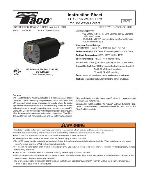
Instruction Sheet<br />
<strong>LTR</strong> - Low Water Cutoff<br />
for Hot Water Boilers<br />
102-338<br />
EFFECTIVE: December 2, 2009<br />
Listings/Approvals:<br />
• UL GUIDE (MBPR) for Limit Controls per UL Standard<br />
353 Limit Controls<br />
• UL GUIDE (MBPR7) Controls, Limit Certified for Canada<br />
CSA Standard C22.2<br />
Maximum Probe Ratings:<br />
Hot water only - 160 psi (11.2kg/cm 2 ) at 250°F (121°C)<br />
Probe Sensitivity: 20K Ohms. Extended operation to 40K Ohms.<br />
Ambient Temperature: 32°F - 120°F (0°C to 49°C)<br />
Enclosure Rating: NEMA 1 for indoor use only<br />
Input Power: 1.5 VA @ 24 VAC supplied by a Class 2 power source<br />
Output Contact: Form B Relay, normally closed (water detected)<br />
5A @ 24 VAC maximum load,<br />
50 VA @ 24 VAC switching<br />
Reset: Automatic reset when water level returns to safe level<br />
Testing: Integrated test switch for testing safety shutdown<br />
General:<br />
The Residential Low Water Cutoff (<strong>LTR</strong>) is a microprocessor based<br />
low water cutoff for detecting the presence to water in a boiler. The<br />
<strong>LTR</strong> uses advanced signal processing to identify when the probe<br />
signal levels have decreased due to possible fouling. These advanced<br />
technologies permit extended operation for probe impedance up to 40K<br />
Ohms. The <strong>LTR</strong> functions longer without requiring probe cleaning, and<br />
it functions normally under non-ideal installation conditions. The <strong>LTR</strong> is<br />
designed for use with hot water boilers and hot water heating boilers.<br />
(See each boiler manufacturers' specifications for recommended<br />
minimum safe water levels.)<br />
During a low water condition, the "Status" LED will illuminate RED.<br />
Under normal conditions, it will illuminate GREEN. See "Status LED<br />
States" table for details.<br />
• Installation must be performed by qualified personnel and in accordance with all national and local codes and ordinances.<br />
• Read all instructions carefully and understand them before starting installation. Save instructions for future use.<br />
• Instruct user how to test and operate this cutoff device as described in these instructions.<br />
• Risk of explosion. Not for use in hazardous locations. Serious injury or death could result.<br />
• The LWCO device must be installed in series ahead of other limit and operating controls installed on the boiler. When installations are complete,<br />
check for correct operation of ALL limit and operating controls.<br />
• For use with hot water boilers and hot water heating boilers only. Use on steam boilers could cause improper operation resulting in property damage,<br />
serious injury, and death.<br />
• Shock Hazard. Disconnect power source before servicing. Serious injury or death could result.<br />
• Use only the wiring harness supplied with the control or factory supplied alternates. Use of other wire harness or insulation types could result in fire<br />
causing property damage, serious injury, or death.<br />
• Hot or pressurized boiler systems can discharge steam and hot water. Cool boiler system to 80º F (27º C) and to 0 psi (0 bar) before servicing.<br />
Failure to do so could result in serious burns.
<strong>LTR</strong> Features:<br />
Process<br />
Connection<br />
<strong>LTR</strong><br />
Connector<br />
Status LED<br />
(Bi-color)<br />
Service LED<br />
(Amber)<br />
Test<br />
Button<br />
Probe<br />
Item<br />
Status LED<br />
Service LED<br />
Test Button<br />
<strong>LTR</strong> Connector<br />
Description<br />
Bi-color LED status indicator. See "LED States" table for details.<br />
Amber LED indicator that service is needed on <strong>LTR</strong> or system.<br />
Push button switch for testing safety shutdown of boiler controls.<br />
Power and relay contact connector.<br />
LED States:<br />
Status LED Service LED Contacts Meaning<br />
Green Off Closed Normal<br />
Green Amber Closed Safe water level, weak probe signal - Service soon.<br />
Red Off Open Low water condition, (LW)<br />
Red Amber Open Probe signal too weak, LW condition - Service now.<br />
Blinking Red Off Open Control failure. Lockout in LW condition.<br />
Off Off Open No power to LWCO.<br />
Installation:<br />
1. Install the probe above the minimum safe water level, as determined from the boiler manufacturer's literature. (See Fig. 1)<br />
NOTE: This may be in a tapping on the boiler or in the boiler supply or return piping.<br />
2. Install the probe to extend into the boiler cavity or piping to make contact with the water.<br />
3. Install the probe so that the exposed portion of the stainless steel is a minimum of 1/4" from any grounding surface inside the<br />
boiler (to prevent the probe from shorting). (See Fig. 2)<br />
4. Hand tighten the <strong>LTR</strong> into the process connection. Do not cross-thread. Do not use a wrench or other tools to tighten the<br />
control.<br />
Fig. 1<br />
Fig. 2<br />
Minimum Safe<br />
Water Level<br />
2-3 Wraps Tefl on®<br />
Tape<br />
• Do not mount device with probe angled upward or deposits can<br />
accumulate on the probe.<br />
• Mount only with probe facing horizontally or vertically downward<br />
and maintain 1/4" minimum clearance from electrode and pipe wall.<br />
• Failure to install probe as directed can cause improper operation<br />
and damage to equipment and property.<br />
• Apply Tefl on® tape only to the threads of the <strong>LTR</strong>. Do not use pipe<br />
dope or other thread sealants. Damage to the control may occur<br />
and result in improper operation.<br />
• Hand tighten the <strong>LTR</strong> into the process connection being careful to not<br />
cross-thread. Do not use a wrench or other tools to tighten the control.<br />
Damage to the control may occur and result in improper operation.
Fig. 3<br />
1.00<br />
2.66<br />
1.79<br />
.79<br />
1.79<br />
3/4” NPT<br />
DWG# 1179-1<br />
Wiring for Boilers with Honeywell Aquastat Models L8124E or L8148E or Equivalent:<br />
Factory Wiring<br />
L8124E<br />
Factory Wiring<br />
L8148E<br />
Female<br />
Connector<br />
RED<br />
Male<br />
Connector<br />
Female<br />
Connector<br />
WHITE<br />
RED<br />
Male<br />
Connector<br />
• Shock hazard. Disconnect power source before servicing. Serious<br />
injury or death could result.<br />
• Only use the wiring harness supplied with the control or factory<br />
supplied alternates. Use of other wire harnesses or insulation types<br />
could result in fire causing property damage, serious injury, and<br />
death.<br />
Ground<br />
Screw<br />
WHITE<br />
GREEN<br />
YELLOW<br />
YELLOW<br />
Ground<br />
Screw<br />
YELLOW<br />
GREEN<br />
YELLOW<br />
Wiring Instructions<br />
1. Connect the WHITE wire to the Aquastat's TV terminal.<br />
2. Connect the RED wire to the Aquastat's Z terminal.<br />
3. Connect the GREEN wire to a ground source that is<br />
electrically common to the boiler ground.<br />
4. Unplug the factory wired quick connector from terminal<br />
B1.<br />
5. Plug the male quick connector on the YELLOW wire into<br />
the female factory wired quick connector.<br />
6. Plug the female quick connector on the YELLOW wire<br />
into terminal B1.<br />
Wiring for Boilers with Honeywell Control Center Model R8285 or Equivalent:<br />
Female<br />
Connector<br />
Factory<br />
Wiring<br />
• Shock hazard. Disconnect power source before servicing. Serious<br />
injury or death could result.<br />
• Only use the wiring harness supplied with the control or factory<br />
supplied alternates. Use of other wire harnesses or insulation types<br />
could result in fire causing property damage, serious injury, and<br />
death.<br />
R8285 or<br />
Equivalent<br />
Male<br />
Connector<br />
YELLOW<br />
Wiring Instructions<br />
1. Connect the WHITE wire to the C terminal.<br />
2. Connect the RED wire to the R terminal.<br />
3. Connect the GREEN wire to a ground source that is<br />
electrically common to the boiler ground.<br />
4. Unplug the factory wired quick connector from the R terminal.<br />
5. Plug the male quick connector on the YELLOW wire into the<br />
female factory wired quick connector.<br />
6. Plug the female quick connector on the yellow wire onto the<br />
R terminal.<br />
Ground<br />
Connection<br />
YELLOW<br />
GREEN<br />
RED<br />
WHITE
Alternate Wiring:<br />
120 VAC<br />
24 VAC Class 2<br />
Transformer<br />
HOT<br />
24 VAC<br />
COMMON<br />
WHITE<br />
GREEN<br />
RED<br />
YELLOW<br />
YELLOW<br />
Limit<br />
Controls<br />
Gas<br />
Valve<br />
Wiring Instructions<br />
1. Connect the WHITE wire to the transformer's common<br />
connection.<br />
2. Connect the RED wire to the transformer's hot output.<br />
3. Connect the GREEN wire to a ground source that is<br />
electrically common to the boiler ground.<br />
4. Cut off the quick connectors from both YELLOW wires and<br />
strip the wire ends.<br />
5. Open the 24 VAC hot connection to the other limit controls<br />
ahead of the fi rst limit control.<br />
6. Wire the YELLOW leads as shown to connect the <strong>LTR</strong>'s<br />
relay in series and ahead of all other limit controls.<br />
Wiring Boilers with an Integrated Control Module:<br />
Integrated Boiler<br />
Control<br />
On boilers equipped with a United Technologies integrated<br />
boiler control module, <strong>Taco</strong> recommends the use of the "Boiler<br />
Module Wiring Harness". This harness is standard on the<br />
<strong>LTR</strong>0243U-1 controls or is available from <strong>Taco</strong>.<br />
1<br />
3<br />
Male<br />
Connector<br />
Boiler Module<br />
Wiring Harness<br />
Wiring Instructions<br />
1. Disconnect the boiler wire harness from the integrated<br />
control module.<br />
2. Plug the boiler wire harness connector into the female<br />
connector on the <strong>LTR</strong> wiring harness.<br />
3. Plug the male connector on the <strong>LTR</strong> wiring harness into the<br />
integrated control module.<br />
4. Plug boiler module module wiring harness into <strong>LTR</strong>.<br />
2<br />
Female<br />
Connector<br />
Factory Wiring<br />
4<br />
• Shock hazard. Disconnect power source before servicing. Serious<br />
injury or death could result.<br />
• Only use the wiring harness supplied with the control or factory<br />
supplied alternates. Use of other wire harnesses or insulation types<br />
could result in fire causing property damage, serious injury, and<br />
death.
Wiring Boilers with an Integrated Control Module<br />
and OEM 4-pin Harness:<br />
4-pin Connector<br />
(#1)<br />
Integrated Control<br />
Module<br />
4-pin Connector<br />
(#2)<br />
Wiring Harness<br />
Wiring Instructions<br />
1. Plug the 4-pin connector on the wiring harness (#1 as<br />
shown) into the integrated control module.<br />
2. Plug the 4-pin connector on the wiring harness (#2 as<br />
shown) into the <strong>LTR</strong>.<br />
Testing:<br />
1. DO NOT fi ll the boiler. Set the thermostat to lowest possible setting and turn on electric power to the boiler. On<br />
initial start-up, the <strong>LTR</strong> indicates a low water condition, which indicates proper function. The "STATUS" LED on the<br />
control unit illuminates RED. The burner should not operate without water in the system.<br />
2. Fill boiler with water. Once water covers the probe, the "STATUS" LED on the control turns from RED to GREEN.<br />
3. Set the thermostat to call for heat. Verify that the burner ignites.<br />
4. With the burner afl ame, press and hold the test switch while observing the burner and the "STATUS" LED on the<br />
<strong>LTR</strong>. After the "STATUS" LED illuminates RED, the burner turns off.<br />
5. Release the test switch and verify that the burner ignites (provided water covers the probe). The "STATUS" LED on<br />
the control unit turns from RED to GREEN.<br />
6. If burner fails to cutoff or relight, see the Troubleshooting section for details. Otherwise, set the thermostat to its<br />
normal setting.<br />
NOTE: Once correct operation of the <strong>LTR</strong> has been tested, test all other safety, limit, and control devices before<br />
fi nalizing system operation.<br />
Cleaning, Maintenance, and Replacemet:<br />
Test the operation of the <strong>LTR</strong> annually, or more frequently, by pressing the “TEST” button. The “STATUS” LED should<br />
turn RED and the boiler should shut down.<br />
Probe must be inspected every 5 years, (or sooner if “SERVICE” LED turns on), for scale build-up or coating. Clean<br />
all oils, fl uxes, and scale from probe with a clean rag.<br />
The control unit should be replaced every 15 years. In areas of high humidity, heavy dust, or other airborne<br />
contaminants more frequent replacement may be required.<br />
Ordering Information:<br />
Replacement Cables:<br />
9300-2714RP - Standard Wire Harness<br />
9300-2715RP - Wire Harness for United Technologies<br />
Integrated Boiler Control<br />
9300-2774RP - OEM 4-pin Harness
Troublshooting:<br />
Symptom Possible Cause Remedy<br />
Boiler will not<br />
fi re<br />
Boiler will not<br />
shutdown<br />
Amber<br />
"SERVICE"<br />
LED is on<br />
No power to <strong>LTR</strong><br />
Low water level<br />
Air pocket at <strong>LTR</strong><br />
probe<br />
Dirty probe<br />
Improper ground<br />
Improper wiring<br />
Failed control<br />
Shorted probe<br />
Improper wiring<br />
Dirty probe<br />
Verify that the <strong>LTR</strong> wiring harness is plugged into the <strong>LTR</strong> and wiring is correct. Be sure power to boiler is<br />
turned on.<br />
Make sure that the water level has reached the <strong>LTR</strong> probe.<br />
Turn off power to the boiler and slowly loosen, but do not remove the <strong>LTR</strong>. Allow any air to escape until water<br />
seeps past the <strong>LTR</strong>'s threads. Promptly re-tighten the <strong>LTR</strong> and apply power to the boiler.<br />
Fluxes or oils used during the construction of the boiler or installation of system piping can coat the <strong>LTR</strong><br />
probe, preventing signals from being received by the <strong>LTR</strong>. Add a cleaning solution, (such as water and<br />
trisodium phosphate or consult the boiler manufacturer), to the system. Heat and circulate this solution for<br />
at least one hour before draining and completely flushing the system with clean water. Remove the <strong>LTR</strong> and<br />
thoroughly wipe it with a clean rag. Refill the system and test for proper operation.<br />
Make sure the green ground wire is electrically common to the boiler. Install the green ground wire to an<br />
unpainted/uncoated surface.<br />
Check all wiring to the <strong>LTR</strong> and refer to the wiring diagrams. Using a multi-meter, verify that incoming power<br />
is 24 VAC.<br />
If the "STATUS" LED blinks RED, the safety circuits in the <strong>LTR</strong> have detected a failure in the control. To<br />
remove any temporary conditions, unplug the <strong>LTR</strong> connector. After 30 seconds, plug in the <strong>LTR</strong> connector. If<br />
the "STATUS" LED continues to blink RED, the control must be replaced.<br />
Turn off power to the boiler and remove the <strong>LTR</strong>. Verify that there is at least 1/4" clearance from all metal<br />
surfaces to the metal probe on the <strong>LTR</strong>. Metal from the boiler or piping must not come in contact with the<br />
metal probe on the <strong>LTR</strong>.<br />
Check all wiring to the <strong>LTR</strong> and refer to the wiring diagrams. Using a multi-meter, verify that incoming power<br />
is 24 VAC.<br />
Deposits form over time in the system and can coat the <strong>LTR</strong> probe, preventing signals from being received<br />
by the <strong>LTR</strong>. Remove the <strong>LTR</strong> and thoroughly wipe it with a clean rag. Refill the system and test for proper<br />
operation. It may be necessary to clean the boiler and piping as noted above.<br />
Limited Warranty Statement<br />
<strong>Taco</strong>, Inc. will repair or replace without charge (at the company’s option) any product or part which is proven defective under normal use within<br />
one (1) year from the date of start-up or one (1) year and six (6) months from date of shipment (whichever occurs fi rst).<br />
In order to obtain service under this warranty, it is the responsibility of the purchaser to promptly notify the local <strong>Taco</strong> stocking distributor or<br />
<strong>Taco</strong> in writing and promptly deliver the subject product or part, delivery prepaid, to the stocking distributor. For assistance on warranty returns,<br />
the purchaser may either contact the local <strong>Taco</strong> stocking distributor or <strong>Taco</strong>. If the subject product or part contains no defect as covered in this<br />
warranty, the purchaser will be billed for parts and labor charges in effect at time of factory examination and repair.<br />
Any <strong>Taco</strong> product or part not installed or operated in conformity with <strong>Taco</strong> instructions or which has been subject to misuse, misapplication, the<br />
addition of petroleum-based fl uids or certain chemical additives to the systems, or other abuse, will not be covered by this warranty.<br />
If in doubt as to whether a particular substance is suitable for use with a <strong>Taco</strong> product or part, or for any application restrictions, consult the<br />
applicable <strong>Taco</strong> instruction sheets or contact <strong>Taco</strong> at [401-942-8000]. <strong>Taco</strong> reserves the right to provide replacement products and parts which<br />
are substantially similar in design and functionally equivalent to the defective product or part. <strong>Taco</strong> reserves the right to make changes in details<br />
of design, construction, or arrangement of materials of its products without notifi cation.<br />
TACO OFFERS THIS WARRANTY IN LIEU OF ALL OTHER EXPRESS WARRANTIES. ANY WARRANTY IMPLIED BY LAW INCLUDING<br />
WARRANTIES OF MERCHANTABILITY OR FITNESS IS IN EFFECT ONLY FOR THE DURATION OF THE EXPRESS WARRANTY SET<br />
FORTH IN THE FIRST PARAGRAPH ABOVE. THE ABOVE WARRANTIES ARE IN LIEU OF ALL OTHER WARRANTIES, EXPRESS OR<br />
STATUTORY, OR ANY OTHER WARRANTY OBLIGATION ON THE PART OF TACO.<br />
TACO WILL NOT BE LIABLE FOR ANY SPECIAL, INCIDENTAL, INDIRECT OR CONSEQUENTIAL DAMAGES RESULTING FROM THE USE<br />
OF ITS PRODUCTS OR ANY INCIDENTAL COSTS OF REMOVING OR REPLACING DEFECTIVE PRODUCTS.<br />
This warranty gives the purchaser specifi c rights, and the purchaser may have other rights which vary from state to state. Some states do<br />
not allow limitations on how long an implied warranty lasts or on the exclusion of incidental or consequential damages, so these limitations or<br />
exclusions may not apply to you.<br />
CONTROLS MADE EASY <br />
TACO, INC., 1160 Cranston Street, Cranston, RI 02920 Telephone: (401) 942-8000 FAX: (401) 942-2360.<br />
TACO (Canada), Ltd., 6180 Ordan Drive, Mississauga, Ontario L5T 2B3. Telephone: 905/564-9422. FAX: 905/564-9436.<br />
Manufactured by POTTER ELECTRIC SIGNAL CO., St. Louis, MO<br />
Printed in USA<br />
Copyright 2008<br />
TACO, Inc.


