401 ; 201
401 ; 201
401 ; 201

Create successful ePaper yourself
Turn your PDF publications into a flip-book with our unique Google optimized e-Paper software.
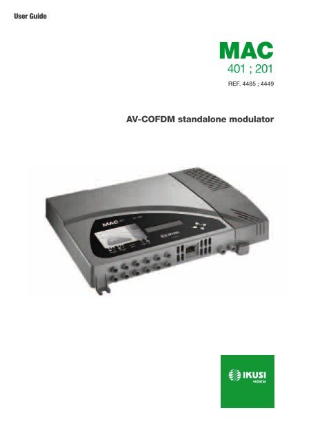
User Guide<br />
MAC<br />
<strong>401</strong> ; <strong>201</strong><br />
REF. 4485 ; 4449<br />
AV-COFDM standalone modulator
Index<br />
30 General safety instructions<br />
30 Types of notices<br />
31 Basic safety instructions<br />
52 Unit recycling<br />
53 CE Certificate<br />
32 Introduction<br />
32 General description<br />
32 Main features<br />
33 General use of the unit<br />
35 Unit installation and configuration<br />
35 Installation<br />
35 Power supply connection<br />
36 Cascade installation<br />
37 Fast menu guide<br />
39 Main menu<br />
39 General Settings<br />
41 Setting the signals<br />
45 Status of the unit<br />
46 Unit information<br />
46 Unblocking the unit<br />
48 Advanced configuration of the unit<br />
49 User interface via web browser<br />
50 Maintenance<br />
50 Unit care<br />
50 Troubleshooting<br />
51 Technical specifications<br />
51 MAC models<br />
52 Warranty
General safety instructions/Types of notices<br />
General safety instructions<br />
JJ<br />
JJ<br />
JJ<br />
Read all of this user manual carefully before plugging in the unit.<br />
Always have these instructions to hand during installation.<br />
Follow all of the instructions and safety notices regarding unit handling.<br />
Types of notices<br />
The meaning of the safety notices used in this manual are described below.<br />
DANGER<br />
DANGER of DEATH OR INJURY<br />
This safety notice indicates a possible danger for the life and health of people.<br />
Not following these instructions may lead to serious consequences to health and<br />
may even cause fatal injuries.<br />
ATTENTION<br />
RISK OF damage to the unit<br />
This safety notice indicates a possible dangerous situation. Not following these<br />
instructions may lead to the unit being damaged.<br />
Note<br />
This type of notice is a note containing applicable advice and useful information<br />
for optimum use of the unit.<br />
HANDLING THE INSIDE OF THE UNIT IS FORBIDDEN<br />
This notice forbids any work that may affect the working order of the unit or its<br />
warranty.<br />
DO NOT DISPOSE OF AS URBAN WASTE<br />
This type of notice indicates that the unit must not be disposed of as unselected<br />
urban waste.<br />
30
General safety instructions/Basic safety instructions<br />
Basic safety instructions<br />
DANGER<br />
DANGER of DEATH OR INJURY<br />
JJ<br />
JJ<br />
Do not install the unit during an electrical storm. This could lead to electrostatic<br />
discharge from lightning.<br />
Do not open the unit. There is a risk of electrostatic discharge.<br />
en<br />
ATTENTION<br />
RISK OF damage to the unit<br />
JJ<br />
JJ<br />
JJ<br />
JJ<br />
JJ<br />
The unit must be appropriately ventilated. Install the unit in a dust-free<br />
location. Do not place the unit in a location where the ventilation slots are<br />
covered or blocked. Install the unit in a location with at least 20 cm around it<br />
free of other objects.<br />
Do not expose the unit to rain or moisture. Install the equipment in a dry<br />
location with no infiltration or condensation of water. Should a liquid enter<br />
the unit, disconnect it immediately from the mains.<br />
Keep the unit away from flammable objects, candles and anything that may<br />
cause a fire.<br />
Connect the unit to an easily accessible power socket. In the event of an<br />
emergency, it will then be possible to quickly unplug the unit.<br />
Do not expose the unit to sources of heat (sun, heating, etc.).<br />
31
Introduction/General description<br />
Introduction<br />
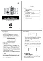
General description<br />
1<br />
KEY<br />
1 Mains connector<br />
2 Front panel with cluster map<br />
3 Display (LCD)<br />
4 Control button<br />
MAC<br />
5 AV input 1<br />
6 AV input 2<br />
7 AV input 3 *<br />
8 AV input 4 *<br />
2<br />
3<br />
4<br />
9 Ethernet connector<br />
10 TV Loopthrough input<br />
11 TV COFDM output<br />
* Available only in MAC <strong>401</strong> model.<br />
MAC<br />
7<br />
8<br />
5<br />
6<br />
9 10 11<br />
Main features<br />
The MAC model is an AV analogue TV signal to COFDM digital TV signal standalone<br />
modulator unit. Suitable for individual residential installations, it is an ideal solution for<br />
the distribution of analogue video signals with COFDM digital TV modulation in a single<br />
standalone unit.<br />
AV1 to AV4 are also serially digitalised, coded in MPEG2 and modulated in COFDM. The<br />
COFDM base band signal is modulated on an RF carrier that can be adjusted at the output<br />
to the VHF and UHF bands.<br />
JJ<br />
Programming:<br />
FF<br />
FF<br />
FF<br />
FF<br />
FF<br />
User interface with LCD display and control button for basic configuration.<br />
User interface from web browser via Ethernet connection.<br />
All settings are automatically memorised.<br />
Reprogrammable as many times as required.<br />
Firmware updated via Ethernet connection with web browser.<br />
32
Introduction/General use of the unit<br />
JJ<br />
JJ<br />
Dimensions: 302 mm x 251 mm x 44 mm<br />
Weight: 1.5 kg<br />
The main characteristics of the MAC model are described below.<br />
en<br />
MAC <strong>201</strong> and MAC <strong>401</strong> models<br />
Recommended for individual residential installations, consisting of two AV inputs and one<br />
RF VHF/UHF output that delivers an output level of >80 dBμV.<br />
JJ<br />
JJ<br />
JJ<br />
Inputs:<br />
FF<br />
FF<br />
FF<br />
2 or 4 CVBS video inputs with stereo audio, as MAC <strong>201</strong> or MAC <strong>401</strong> model<br />
respectively.<br />
Supported video standards: PAL/SECAM/NTSC<br />
RF loopthrough input.<br />
Processing:<br />
FF<br />
FF<br />
Video: MPEG2 and MPEG4 Layer II.<br />
Audio: MPEG1 Layer II.<br />
FF<br />
Quality: DVD full D1.<br />
FF<br />
FF<br />
Generates the PSI tables: PAT, PMT, SDT, NIT, TDT and TOT.<br />
LCN processing.<br />
Outputs:<br />
FF<br />
DVB-T output according to ETSI EN 300 744.<br />
FF<br />
FF<br />
FF<br />
FF<br />
Output MER > 38 dB (typical).<br />
Band aliasing < -45 dB.<br />
Output frequency bands: VHF + UHF.<br />
Average output level 80 dBμV.<br />
General use of the unit<br />
Below is described how to operate the unit using the control button and interpret the visual<br />
indications on the LCD display. The program comprises a main menu made up of sub-menus<br />
that can be selected to modify the basic operation settings of the unit.<br />
Visual indications on the LCD display<br />
This symbol visually indicates the possibility of moving vertically.<br />
33
Introduction/General use of the unit<br />
Vertical button movement<br />
In the menus and submenus, move the button up or down to browse<br />
upwards and downwards position by position.<br />
In the settings, move the button up or down to modify values position by<br />
position.<br />
NOTE<br />
Keep the button pressed up or down to browse or to modify<br />
values more quickly.<br />
Horizontal button movement<br />
In the menus, move the button to the left or the right to select and go<br />
back position by position.<br />
In the settings, move the button to the left or the right to select and go<br />
back position by position.<br />
NOTE<br />
Keep the button pressed to the left or to the right to browse<br />
more quickly.<br />
Press button<br />
In the menus, this selects the submenu.<br />
In the submenus, this selects the setting.<br />
In the settings, this selects the parameter value.<br />
34
Unit installation and configuration/Installation<br />
Unit installation and configuration<br />
The LCD display and the control button are sufficient for the basic settings of the unit.<br />
Follow the steps indicated below to install the unit and configure the various parameters<br />
accessible from the user interface on the LCD display.<br />
en<br />
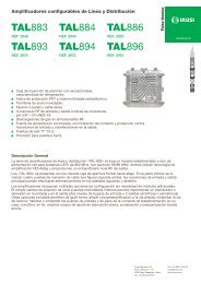
Installation<br />
ATTENTION<br />
RISK OF damage to the unit<br />
Mechanical handling of the unit while<br />
it is switched on may lead to it being<br />
damaged. Do not plug the unit into the<br />
mains before or during installation.<br />
1) Fit and tighten the bolts and plugs securing<br />
the unit to the wall.<br />
2) Connect AV inputs in the respective RCA<br />
connectors.<br />
3) You can also connect the coaxial cable from<br />
the RF loopthrough input (connector F).<br />
4) Connect the coaxial cable from the output to<br />
the unit (connector F).<br />
NOTE<br />
Illustration above only applies to the MAC <strong>401</strong> model.<br />
For MAC <strong>201</strong> model only AV1 and AV2 inputs are available.<br />
video 1<br />
audio L1<br />
audio R1<br />
video 2<br />
audio L2<br />
audio R2<br />
2<br />
video 3<br />
audio L3<br />
MAC<br />
audio R3<br />
video 4<br />
audio L4<br />
audio R4<br />
TV (loopthrough)<br />
network<br />
1<br />
TV+AV1+AV2+AV3+AV4 to distribution<br />
3<br />
4<br />
Power supply connection<br />
DANGER<br />
DANGER of DEATH OR INJURY<br />
Incorrect unit power connection may<br />
cause an electric shock. Follow the<br />
steps below for the electrical installation<br />
of the unit.<br />
2<br />
3<br />
1) Connect the earth cable.<br />
MAC<br />
2) Connect the power plug to the unit mains<br />
connector.<br />
3) Connect the power plug to the mains socket.<br />
1<br />
35
MMAC<strong>401</strong><br />
Ref. 485<br />
www.ikusi.com<br />
MMAC<strong>401</strong><br />
Ref. 485<br />
www.ikusi.com<br />
Unit installation and configuration/Cascade installation<br />
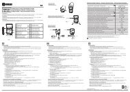
Cascade installation<br />
The MAC unit has a maximum capacity to include 4 AV analogue TV signals at the RF VHF/<br />
UHF output, coded as COFDM Digital TV signals.<br />
To increase this capacity, several MAC units can be cascade connected. The maximum<br />
capacity of a group of N units is 2xN or 4xN TV signals included, as MAC <strong>201</strong> or MAC <strong>401</strong><br />
model respectively.<br />
To cascade connect 2 or more units, connect the RF output 4 of the previous unit to the<br />
TV input (loopthrough) 3 of the next unit (see Installation figure).<br />
MAC <strong>401</strong> Ref.4485<br />
MAC <strong>401</strong> Ref.4485<br />
TV + AV1 + AV2 +AV3 + AV4<br />
TV + AV1 + AV2 +AV3 + AV4<br />
+AV5 + AV6 + AV7 + AV8<br />
TV (loopthrough)<br />
video 1<br />
audio L1<br />
audio R1<br />
video 2<br />
audio L2<br />
audio R2<br />
video 3<br />
audio L3<br />
audio R3<br />
video 4<br />
audio L4<br />
audio R4<br />
vidéo 5<br />
audio L5<br />
audio R5<br />
vidéo 6<br />
audio L6<br />
audio R6<br />
vidéo 7<br />
audio L7<br />
audio R7<br />
vidéo 8<br />
audio L8<br />
audio R8<br />
AV 2 Soruce<br />
AV 1 Soruce<br />
AV 3 Soruce<br />
AV 4 Soruce<br />
AV 6 Soruce<br />
AV 5 Soruce<br />
AV 7 Soruce<br />
AV 8 Soruce<br />
NOTE<br />
Illustration above only applies to the MAC <strong>401</strong> model.<br />
For MAC <strong>201</strong> model only AV1 and AV2 inputs are available.<br />
For installations with 2 or more units, each one must be identified with a different TSID<br />
value and each service identified with a different SID value.<br />
To configure TSID and SID values, perform advanced unit configuration (see Advanced<br />
configuration of the unit section).<br />
NOTE<br />
The process of advanced configuration of the unit is explained in the J<br />
“Web interface user manual” available at http://www.ikusi.com.<br />
36
Unit installation and configuration/Fast menu guide<br />
Fast menu guide<br />
en<br />
Go to next page<br />
37
Unit installation and configuration/Fast menu guide<br />
Go to previous page<br />
Go to previous page<br />
38
Unit installation and configuration/Main menu<br />
Main menu<br />
Note<br />
Over the following pages, the field locating and selection method is primarily<br />
indicated by the “vertical button movement” and “press button” icons. However,<br />
horizontal button movement can be used to locate and select fields, as indicated<br />
in the General use of the unit.<br />
en<br />
1) After switching on the unit the initial display appears<br />
informing of the model, firmware version,<br />
output frequency and information on alarms and<br />
status:<br />
FF<br />
FF<br />
Alarms:<br />
ÌÌ<br />
ÌÌ<br />
Status:<br />
ÌÌ<br />
ÌÌ<br />
A:0 = no alarms<br />
A:X = alarms present<br />
S:X = status correct<br />
S:0 = status incorrect<br />
2) Press the control button to access the main<br />
menu.<br />
General Settings<br />
1) In the main menu, locate and select<br />
GENERAL.<br />
IP configuration<br />
note<br />
The IP configuration affects the Ethernet interface.<br />
note<br />
To introduce a sequence of digits in the display move the control button vertically<br />
to change the value of the current digit and horizontally to move between digits.<br />
1) Locate and select the option IP.<br />
a) Locate and select the option DHCP to<br />
activate (ON) or deactivate (OFF) dynamic<br />
IP assigning. If this is deactivated, a static<br />
IP must be configured.<br />
39
Unit installation and configuration/General Settings<br />
b) Locate and select the option IP address.<br />
Enter the 12-digit sequence<br />
corresponding to the static IP address of<br />
the unit.<br />
c) Locate and select the option IP mask.<br />
Enter the 12-digit sequence corresponding<br />
to the IP mask of the unit.<br />
d) Locate and select the option DEFAULT<br />
Gateway. Enter the 12-digit sequence<br />
corresponding to the IP direction of the<br />
LAN gateway.<br />
Setting the time<br />
2) Locate and select the option time-Date.<br />
a) Locate and select time-Date to configure<br />
the time and date of the unit in the<br />
format hh:mm yyyy-mm-dd.<br />
b) Locate and select the option Time<br />
SUBzone to configure the reference time<br />
zone.<br />
Selecting the country<br />
3) Locate and select the option Country to<br />
select the reference country.<br />
Setting the language<br />
4) Locate and select the option Language to<br />
establish the language of the menus on the<br />
display: español, english, français.<br />
Blocking the LCD and joystick<br />
5) Locate and select the option Block LCD to<br />
block access to the configuration from the LCD<br />
display and using the control button.<br />
a) Activate (ON) or deactivate (OFF) the<br />
blocking option.<br />
b) Establish a code to unlock the unit if this<br />
option has been activated.<br />
40
Unit installation and configuration/Setting the signals<br />
Restoring factory settings<br />
6) Locate and select the option Factory settings<br />
to restore the factory settings of the<br />
unit.<br />
en<br />
Select the option delete to delete all the modifications<br />
entered in the configuration by the installer<br />
or operator of the unit.<br />
Setting the signals<br />
note<br />
The unit can switch the input signals; alter their brightness, contrast and saturation<br />
conditions; and adjust the output carrier in RF.<br />
1) Locate and select the option Settings.<br />
Configuring the input signals<br />
1) Locate and select the option Input.<br />
2) Locate and select the option Input and the<br />
number corresponding to the input you want<br />
to configure: 1 to 2 for MAC <strong>201</strong> and 1 to 4 for<br />
MAC <strong>401</strong>.<br />
a) Locate and select the option ch1:*****<br />
bright to check the type of input signal,<br />
the video and audio detection, and configure<br />
the brightness of the video signal (1<br />
to 255).<br />
b) Locate and select the option Cont1<br />
saturation to configure the contrast<br />
and saturation of video signal 1 (1 to 255).<br />
c) Locate and select the option inp AUDIO<br />
ATT 1 to configure the attenuation of audio<br />
signal 1 in dB (1 to 40)<br />
d) Locate and select the option Sharpness<br />
1 to configure the sharpness of video signal<br />
1 (High, Medium, soft or None).<br />
41
Unit installation and configuration/Setting the signals<br />
e) Locate and select the option Coding 1.<br />
This configures the coding parameters:<br />
MPEG2 or MPEG4 Layer2.<br />
f) Locate and select the option Aspect<br />
ratio. The possible aspect ratio values<br />
are 1:1, 4:3 and 16:9.<br />
g) Locate and select the option VIDEO BI-<br />
TRATE. The unit can be configured for a<br />
data coding speed at input of 3 to<br />
8 Mbits/s.<br />
h) Locate and select the option AUDIO<br />
BITRATE. The unit can be configured for a<br />
data coding speed at input of 96; 128; 160;<br />
192; 224; 256; 320 and 384 Kbits/s.<br />
note<br />
If you keep pressing the control button down you will access the information and<br />
configuration of the following input signals.<br />
Configuration of the carrier services<br />
1) Locate and select the option Services.<br />
2) Locate and select the option SERvices and<br />
the number corresponding to the input you<br />
want to configure: 1 to 2 for MAC <strong>201</strong> and 1 to<br />
4 for MAC <strong>401</strong>.<br />
a) Locate and select the option CH1 video<br />
audio. Activate (ON) or deactivate (OFF)<br />
the video and audio signals of the first<br />
input.<br />
b) Locate and select ch1 lcn. Configure the<br />
LCN value of the signal.<br />
c) Locate and select ch1 SID. Configure the<br />
SID value of the signal.<br />
d) Locate and select CH1 Name. Assign a<br />
name to the signal in CH1.<br />
42
Unit installation and configuration/Setting the signals<br />
note<br />
If you keep pressing the control button down you will access the information and<br />
configuration of the following input signals.<br />
en<br />
Configuration of the output signal<br />
note<br />
To introduce a sequence of digits in the display move the control button vertically<br />
to change the value of the current digit and horizontally to move between<br />
digits.<br />
note<br />
Position the cursor to the right of the current value and move the control button<br />
vertically to increase or decrease the current value. Hold the control button up or<br />
down to increase or decrease the current value more quickly.<br />
3) Locate and select the option Output.<br />
a) Locate and select the option Frequency.<br />
Configure the output frequency value<br />
between 45 MHz and 865 MHz.<br />
b) Locate and select the option Attenuation.<br />
Select the output attenuation<br />
between 0 and 47 dB.<br />
c) Locate and select the option OFDM<br />
mode. Select the OFDM mode between<br />
2k and 8k subcarriers.<br />
d) Locate and select the option Bandwidth.<br />
Select the bandwidth between 6,<br />
7 and 8 Mhz.<br />
e) Locate and select the option Guard<br />
interval. Select the guard interval between<br />
1/32, 1/16, 1/8 and 1/4 of symbol.<br />
f) Locate and select the option Constellation.<br />
Select the modulation constellation<br />
between 16qam and 64qam.<br />
43
Unit installation and configuration/Setting the signals<br />
g) Locate and select the option Code rate.<br />
Select the code rate between 1/2, 2/3, 3/4,<br />
5/6 and 7/8.<br />
Network configuration<br />
note<br />
To introduce a sequence of digits in the display move the control button vertically<br />
to change the value of the current digit and horizontally to move between<br />
digits.<br />
note<br />
Position the cursor to the right of the current value and move the control button<br />
vertically to increase or decrease the current value. Hold the control button up or<br />
down to increase or decrease the current value more quickly.<br />
4) Locate and select the option Network.<br />
a) Locate and select the option Name. Configure<br />
the name of the network.<br />
b) Locate and select the option Provider.<br />
Configure the name of the network service<br />
provider.<br />
c) Locate and select the option NID.<br />
Configure the value of the network identifier.<br />
d) Locate and select the option TSID.<br />
Configure the value of the trasport stream<br />
identifier.<br />
e) Locate and select the option ONID. Select<br />
the guard interval between 1/32, 1/16, 1/8<br />
and 1/4 of symbol.<br />
f) Locate and select the option NIT MODE.<br />
Configure the NIT mode:<br />
ÌÌ<br />
OFF: NIT is not inserted (the LCN values<br />
are ignored).<br />
44
Unit installation and configuration/Status of the unit<br />
ÌÌ<br />
ÌÌ<br />
Without model: the NIT generated<br />
by the unit is inserted.<br />
Integration with model NIT: the information generated by the unit is<br />
integrated in a selected model NIT. If the TSID coincides, it replaces the information<br />
in the model NIT with that of the unit.<br />
g) Locate and select the option NIT LCN<br />
MODE. Allows you to select the mode of<br />
the NIT LCNs:<br />
ÌÌ<br />
ÌÌ<br />
ÌÌ<br />
ÌÌ<br />
ÌÌ<br />
ÌÌ<br />
OFF: the LCN descriptor is not inserted in the NIT<br />
Europe Mode: the descriptor for Europe is inserted.<br />
Independent Television Commission: the descriptor for the UK is<br />
inserted.<br />
Nordig mode V1: the descriptor according to the Nordig V1 specification is<br />
inserted.<br />
Nordig mode V2: the descriptor according to the Nordig V2 specification is<br />
inserted.<br />
Generic Mode: generic LCN descriptor.<br />
h) Locate and select the option TDT-TOT<br />
MODE.. Allows deactivating date and hour<br />
insertion in the receptor.<br />
Status of the unit<br />
en<br />
note<br />
The unit lets you see its status in detail and the existence of active alarms in the<br />
module.<br />
1) Locate and indicate Status.<br />
a) Locate and indicate Status: **. The unit<br />
displays its status and alarms: OK / Error.<br />
b) Locate and indicate output bitrate.<br />
The unit displays the output data speed in<br />
mbits/s.<br />
c) Locate and indicate min act max<br />
null. The unit displays the volume of<br />
null data packets in the output (minimum,<br />
actual and maximum) as a percentage of<br />
the total.<br />
d) Locate and indicate Temperature. The<br />
unit displays its temperature.<br />
45
Unit installation and configuration/Unit information<br />
Unit information<br />
1) Locate and indicate the option Module<br />
info.<br />
a) Locate and indicate the option Model.<br />
The unit displays its model and version.<br />
b) Locate and indicate the option Serial<br />
number. The unit displays its serial<br />
number.<br />
c) Locate and indicate the option MAC. The<br />
unit displays its MAC address.<br />
d) Locate and indicate the option Version.<br />
The unit displays its software version.<br />
Unblocking the unit<br />
The unit can be blocked from the web interface<br />
preventing the user operating the display and the<br />
control button to modify the configuration.<br />
To unblock the unit:<br />
1) Locate and select Blocking code.<br />
2) Enter the unblocking code assigned by the unit<br />
operator through the web interface.<br />
3) The unit displays the validity of the code.<br />
note<br />
The unit will remain unblocked until it is restarted or the operator deactivates the<br />
block from the web interface.<br />
To unblock the unit without the blocking code:<br />
1) Locate and select Information.<br />
46
Unit installation and configuration/Unblocking the unit<br />
2) Contact the supplier of the unit and provide the<br />
serial number. The supplier of the unit will provide<br />
an unblocking code for the serial number<br />
indicated.<br />
en<br />
47
Advanced configuration of the unit/User interface via web browser<br />
Advanced configuration of the unit<br />
User interface via web browser<br />
The web interface allows you to fully configure the MAC unit through an Ethernet connection<br />
and a web browser.<br />
NOTE<br />
To display the graphics provided in the unit configuration program correctly, we<br />
recommend installing the web browser Mozilla Firefox 1.5 or higher (www.mozilla.<br />
com) in the control PC.<br />
NOTE<br />
Cookies and Javascript must be enabled.<br />
NOTE<br />
Use a PC with an Ethernet network card and an Ethernet CAT-5E crossover cable.<br />
1) Access the TCP/IP properties of the PC and configure the following parameters:<br />
FF<br />
IP address of the PC: 192.168.1.1<br />
FF<br />
Subnet mask: 255.255.255.0<br />
2) Connect the PC to the LAN (RJ-45) port of the MAC unit (see number 11 on the diagram<br />
in the section General description).<br />
NOTE<br />
The initial process must be made in local mode, although later you will be able to<br />
access the unit from any PC in the LAN.<br />
NOTE<br />
The Ethernet connector of the MAC has two indicator lights:<br />
JJ<br />
JJ<br />
The link is correct when the link LED (to the left of the Ethernet connector) is<br />
lit.<br />
There is activity in the link when the activity LED (to the right of the Ethernet<br />
connector) is flashing.<br />
3) Launch the web browser and enter the MAC unit's IP address:<br />
FF<br />
Initial IP address: 192.168.1.6<br />
NOTE<br />
This initial IP address may be modified by the user.<br />
48
Advanced configuration of the unit/User interface via web browser<br />
NOTE<br />
The unit also has the IP address 10.254.254.254 assigned by default.<br />
This IP address may not be modified by the user.<br />
en<br />
4) Press ENTER to access to the welcome<br />
screen.<br />
5) Enter the user name “Admin” and the password<br />
“admin”.<br />
NOTE<br />
The process of configuration and setting<br />
via Ethernet connection is explained in the<br />
“Web interface user manual” available at<br />
http://www.ikusi.com.<br />
49
Maintenance/Unit care<br />
Maintenance<br />
Unit care<br />
HANDLING THE INSIDE OF THE UNIT IS FORBIDDEN<br />
Do not dismantle or try to repair the unit, its accessories or its components. This<br />
will render the warranty null and void.<br />
JJ<br />
JJ<br />
JJ<br />
JJ<br />
JJ<br />
Do not use the power cable if it is damaged.<br />
To disconnect the power cable, pull carefully on the plug and not the cable.<br />
To clean the panel and unit connections:<br />
FF<br />
FF<br />
FF<br />
Unplug the unit.<br />
Clean with a slightly damp, soft cloth.<br />
Allow to dry completely before use.<br />
Do not spill liquid onto the unit.<br />
Keep ventilation slots free of dust and any foreign bodies.<br />
Troubleshooting<br />
The most frequent problems arising during unit installation are indicated below. If you encounter<br />
any other type of problem, please contact the unit sales team.<br />
Problem Possible cause What to do<br />
Forgotten unlock code. - Contact your supplier.<br />
Nothing appears on LCD<br />
display.<br />
The power cable is not connected<br />
properly.J<br />
Check the power cable.<br />
50
Technical specifications/MAC models<br />
Technical specifications<br />
MAC models<br />
en<br />
Inputs AV1 / AV2 /AV3 * / AV4 *<br />
Format<br />
CVBS<br />
Input level (video) Vpp 0,7 - 1,4<br />
Input impedance Ω 75<br />
Video standards<br />
PAL/SECAM/NTSC<br />
Analogue / digital audio<br />
Yes / No<br />
Input level (audio) Vpp 0,5 - 4,0<br />
* Available only in MAC <strong>401</strong> model.<br />
Output<br />
COFDM digital TV<br />
COFDM standard DVB-T according to ETSI EN 300 744<br />
Bandwidths MHz 6 / 7 / 8<br />
Number of carriers<br />
2K / 8K<br />
MER dB 38 (typical)<br />
Central frequency MHz 51 - 858<br />
Level dBμV 80<br />
Output pitch attenuation dB 1<br />
Impedance Ω 75<br />
Frequency pitch kHz 1<br />
Level adjustment dB -15<br />
Frequency stability ppm ≤±30<br />
Band aliasing dB ≤-50<br />
Noise level (∆B = 8 MHz) dBc ≤-70<br />
Web user interface<br />
Electric standard<br />
LAN connector<br />
Protocols<br />
Ethernet 10BaseT<br />
10/100 Mbps<br />
RJ-45<br />
HTTP / UDP<br />
Operations<br />
Mains voltage 230 - 240 V~<br />
Consumption<br />
0.45 A / 30 W<br />
Operating temperature 0 to 45 ºC<br />
Mains connector<br />
IEC C8<br />
51
Warranty/MAC models<br />
Warranty<br />
Notwithstanding any complaints made to the direct vendor of the product, IKUSI offers unit<br />
users a two-year warranty as of the invoice date, which shall become valid on presenting<br />
the receipt of purchase.<br />
During the warranty period, IKUSI is responsible for any faults arising due to material or<br />
manufacturing defects and shall repair the receiver or replace it for another corresponding<br />
to the state of technology at that time. The warranty does not cover any faults or defects<br />
due to misuse or non-fulfilment of the information given in this installation manual.<br />
All complaints other than those indicated are not included in the warranty. More specifically,<br />
the warranty does not cover services provided by the authorised vendor (e.g. installation,<br />
configuration or programme updates) or the repair of any damages or injuries caused to the<br />
client or others as a result of the installation or of receiver operations.<br />
Unit recycling<br />
Recycling of electrical and electronic equipment<br />
(Applicable in the European Union and in European countries with selective<br />
waste collection systems.)<br />
This symbol on your unit or its packaging indicates that this product cannot be<br />
treated as general domestic waste and must be handed in at the corresponding<br />
point of collection for electric and electronic equipment. By ensuring this product<br />
is disposed of correctly you will help prevent negative consequences for the<br />
environment and human health, which could otherwise be caused by inappropriate<br />
waste handling of this product. Recycling of materials helps preserve natural<br />
resources. For more detailed information on the recycling of this product, please<br />
contact your local council, your nearest collection point or the distributor from<br />
whom you purchased the product.<br />
52
CE Certificate/MAC models<br />
CE Certificate<br />
By reproducing the CE marking, IKUSI guarantees unit compliance with the corresponding<br />
harmonised standards.<br />
en<br />
EC-Declaration of Conformity<br />
marking<br />
We, Manufacturer<br />
IKUSI, Angel Iglesias, S.A.<br />
Paseo Miramón, 170<br />
E-20009 San Sebastián, Spain<br />
declare that the product<br />
E M C L V D<br />
Council Directive 2006/95/CE<br />
Council Directive 2004/108/CE<br />
(EMC Directive)<br />
Standards to which conformity is declared :<br />
AV-COFDM Autonomous Modulator<br />
MAC-<strong>201</strong> ; MAC-<strong>401</strong><br />
is in conformity with<br />
and<br />
(Low Voltage Directive)<br />
Standards to which conformity is declared :<br />
EN 50083-2 :2007<br />
Cabled distribution systems for television and sound signals.<br />
Part 2: Electromagnetic compatibility for equipment.<br />
EN 60728-11 :2005<br />
Cabled Distribution Systems for Television and Sound<br />
Signals. Part 11: Safety Requirements.<br />
EN 60065 :2003<br />
Safety requirements for mains operated electronics<br />
and related apparatus for household and similar general<br />
use.<br />
San Sebastián, July <strong>201</strong>2<br />
Luis Rodríguez Navarrete<br />
R&D Director<br />
53
Ángel Iglesias, S.A.<br />
Paseo Miramón, 170<br />
20014 San Sebastián, Spain<br />
Tel. +34 943 44 88 00<br />
Fax +34 943 44 88 20<br />
ikusi@ikusi.com<br />
www.ikusi.tv<br />
1<strong>201</strong>48B