Create successful ePaper yourself
Turn your PDF publications into a flip-book with our unique Google optimized e-Paper software.
SERVICE WE DELIVER AND QUALITY YOU CAN DEPEND ON<br />
ANCHOR DANLY is a leading manufacturer of die sets and die component products supplied globally to the parts<br />
forming industry. Backed by years of tool and die experience, quality and innovation are some of the reasons why<br />
our name is respected throughout the world. We have taken the lead role in creating and bringing new products to<br />
customers and helping them find solutions that improve their operations. Based on the capabilities ANCHOR DANLY<br />
offers, we can help you to meet the demands of quick deliveries, technical support, quality products and competitive<br />
prices. ANCHOR DANLY and its’ broad distribution channels and direct sales personnel will assist you in any way to<br />
make your product a better and more profi table one.<br />
Whether standard or sutomized products, with our years of experience, customeres can be sure the products<br />
they receive will meet their expectations for reliability and dependable performance. We understand the demanding<br />
schedules of die builders and production personnel and have developed efficient manufacturing processes to shorten<br />
product lead times as well as put inventory on our shelves so you can have it in your facility when you need it. Put<br />
the ANCHOR DANLY network to work for you. We’ve got the service you’ve been looking for.<br />
Included in our full line offering are both inch and metric size die sets and die components that are designed<br />
to numerous die standards including ISO, NAAMS, JIS and many large automotive and appliance manufacturers’<br />
standards. The complete product offering includes:<br />
‣ Accu-Bend Rotary Benders<br />
‣ Air Presses<br />
‣ Cams<br />
• Aerial & Diemount Cams<br />
• Box Cams<br />
• Roller Cams<br />
• Wide Cams<br />
‣ Die Accessories<br />
‣ Die Sets<br />
• Plain & Ball Bearing Sets<br />
• Catalog Ball Bearing Sets<br />
• Wear Plate Sets<br />
• Cast Sets<br />
‣ Ejector Boxes<br />
‣ Guide Posts & Bushings<br />
• Plain & Ball Bearing Styles<br />
• Steel, Bronze, Bronze-Plated &<br />
Self-Lubricating Bushings<br />
• Lempcoloy ® Bushings<br />
• Special Pins, Bushings & Retainers<br />
‣ Hydraulics<br />
• Electronic Die Setters<br />
• Die Separators<br />
• Drill & Tap Equipment<br />
• Hydraulic Motors<br />
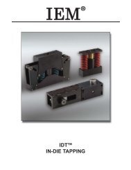
‣ In-Die Tapping Units<br />
‣ Machined and Cut Ground Plate<br />
• Adapter Plates<br />
• Bolster Plates<br />
• 1020, 1045 & 4140 Materials<br />
‣ Manufacturing Services<br />
• CNC Machining<br />
• Blanchard Grinding<br />
• Stress Relieving<br />
• • Die Set Repair<br />
‣ Mold Components<br />
• Bronze Plated & Self-Lubricated Bushings<br />
• Leader Pins<br />
• Bronze & Bronze Plated Wear Strips & Ways<br />
‣ Punches, Buttons & Retainers<br />
‣ Reliance Fabrications<br />
• Custom Fabrications<br />
• Robotic Welding<br />
• Aluminum & Steel Fixture Bases<br />
‣ <strong>Springs</strong><br />
• DieMax TM L Inch Series <strong>Springs</strong><br />
• DieMax XL TM Series ISO <strong>Springs</strong><br />
• JIS Series <strong>Springs</strong><br />
• Custom Heavy Duty <strong>Springs</strong><br />
• Marsh Mellow ® <strong>Springs</strong><br />
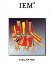
• Formathane ® Urethane<br />
• Kaller Gas <strong>Springs</strong><br />
• <strong>Utility</strong> & Disc <strong>Springs</strong><br />
‣ Wear Products<br />
• Plates, Strips, Gibs & Blocks<br />
• Steel, bronze, Bronze-Plated and<br />
Self-Lubricating Materials
UTILITY SPRINGS<br />
MM x .039837 = INCHES<br />
KG X 2.20463= LBS.<br />
OD<br />
Inches<br />
Part<br />
Number<br />
ROUND WIRE DIE • FIXTURE SPRINGS<br />
10 & 18 INCH LENGTHS • PLAIN ENDS<br />
MUSIC WIRE • 10” LENGTHS<br />
CARBON STEEL • 18” LENGTHS<br />
Max.<br />
Rod<br />
Dia.<br />
Wire<br />
Dia.<br />
Coils<br />
Per<br />
Inch<br />
Pounds<br />
per Inch<br />
of Compression<br />
No.<br />
per<br />
Box<br />
OD<br />
Inches<br />
Part<br />
Number<br />
Max.<br />
Rod<br />
Dia.<br />
Wire<br />
Dia.<br />
Coils<br />
Per<br />
Inch<br />
Pounds<br />
per Inch<br />
of Compression<br />
.087 RW-1 .062 .010 28 .135<br />
.479 RW-9 .355 .041 4.5 .6<br />
.089 RW-1A .062 .014 28.5 .6 .493 RW-9A .355 .054 4 2.1<br />
.116 RW-2 .092 .012 25 .11 .520 RW-9B .355 .062 5.75 2.0<br />
.120 RW-2A .078 .016 25 .4 .532 RW-9C .355 .072 4 5.25<br />
.176 RW-3 .141 .014 14 .1 .612 RW-10 .500 .054 3 1.31<br />
.180 RW-3A .141 .018 14 .3 .678 RW-10A .531 .062 3 1.9<br />
.180 RW-3B .125 .026 13 1.95 .676 RW-10B .531 .072 3.25 3.25<br />
.178 RW-3C .094 .035 19 5.6 .675 RW-10C .531 .068 3.5 2.5<br />
.240 RW-4 .188 .018 9.5 .31 .805 RW-11 .672 .062 2.5 1.3<br />
.238 RW-4A .188 .022 11 .26 .805 RW-11A .625 .080 2.5 3.5<br />
.241 RW-4B .188 .026 9.5 .78 .865 RW-11B .656 .098 2.25 8.0<br />
.248 RW-4C .171 .031 10 1.6 .922 RW-11C .640 .125 2.75 15.0<br />
.242 RW-4D .171 .035 13 2.3 .921 RW-12A .750 .080 2.5 2.1<br />
.238 RW-4E .141 .041 9 6.25 .975 RW-12B .781 .098 2 5.75<br />
.243 RW-4F .141 .047 10 11.0 1.020 RW-13 .844 .085 2.25 2.1<br />
.302 RW-5 .250 .022 10 .175 1.020 RW-12C .750 .125 2 13.5<br />
.304 RW-5A .234 .031 11 .65 1.100 RW-12 .828 .125 2.75 7.75<br />
.304 RW-5B .219 .037 11 1.5 1.055 RW-12D .765 .135 3 11.0<br />
.303 RW-5C .219 .041 8 3.25 1.145 RW-13A .890 .125 2 9.0<br />
.305 RW-5D .203 .047 7.5 6.5<br />
12<br />
1.145 RW-14 .953 .090 1.75 2.5<br />
.302 RW-5E .185 .055 8 12.5 1.343 RW-14A 1.031 .148 1.75 14.0<br />
.366 RW-6 .304 .031 11 .57 1.591 RW-15 1.281 .148 1.5 8.75<br />
.361 RW-6A .281 .035 10 .675 1.820 RW-16 1.500 .148 1.75 5.0<br />
.365 RW-6B .266 .043 7 2.15<br />
.368 RW-6C .266 .047 8.5 2.8<br />
.365 RW-6D .250 .055 6 8.2<br />
.365 RW-6E .234 .062 6.5 13.0<br />
.368 RW-6F .203 .075 7 28.0<br />
.426 RW-7 .344 .035 7 .55<br />
.425 RW-7A .328 .047 7 2.0<br />
.425 RW-7B .297 .055 6 4.7<br />
.427 RW-7C .281 .062 6.5 7.4<br />
.429 RW-7D .266 .075 5.5 20.0<br />
.430 RW-7E* .250 .085 6 35.0<br />
.488 RW-8 .406 .035 9 .28<br />
.488 RW-8A .391 .047 7.5 1.2<br />
.495 RW-8B .375 .055 7 2.5<br />
.492 RW-8C .360 .062 4 7.4<br />
.490 RW-8D .325 .075 4.5 15.0<br />
.495 RW-8E* .310 .091 5 33.0<br />
.500 RW-8F* .270 .115 5.5 95.0<br />
*Indicates carbon steel; All other items music wire<br />
Compression Spring Assortment<br />
111-850 (R50)<br />
ASSORTMENT CONSISTS OF<br />
1 EACH OF THE 18” LONG<br />
SPRINGS<br />
No.<br />
per<br />
Box<br />
12<br />
6<br />
11-845 (R-45)<br />
ASSORTMENT<br />
CONSISTS OF<br />
2 EACH OF<br />
ABOVE 10”<br />
LONG SPRINGS<br />
COMPRESSION<br />
SPRING<br />
FORMULA TO CALCULATE LBS. PER INCH<br />
FOR ALL ALTERED SPRINGS<br />
A X B<br />
= D<br />
C<br />
A = Catalog Free Length<br />
B = Rate in lbs. Per Inch, Per “A”<br />
C = Req’d Cut Free Length<br />
D = Lbs. Per Inch of Req’d Free Length<br />
Specials Quoted Upon Request<br />
1
UTILITY SPRINGS<br />
IN STOCK<br />
COMPRESSION SPRINGS • STEEL FIXTURE<br />
INCHES X 25.4 = mm LBS. X .454 = kg<br />
Comp.<br />
O.D. Max. Length<br />
Total Type of<br />
Part Number Wire Dia. rate per<br />
Inches Rod Dia. Inches<br />
Coils Ends<br />
Inch Lbs.<br />
.078 .047 .53 020-074 (G-74) .012 4.87 17 Plain<br />
.078 .047 .56 020-073 (G-73) .011 3.87 18 Plain<br />
.108 .062 .81 020-076 (G-76) .018 12.50 16 Plain<br />
.110 .062 .91 020-075 (G-75) .018 9.25 22 Plain<br />
.120 .078 .62 020-125 (G-125) .016 6.60 13 Squared<br />
.120 .075 .75 020-126 (G-126) .016 5.30 18 Squared<br />
.170 .141 .21 020-077 (G-77) .012 .75 7 Plain<br />
.178 .141 10.00 020-056 (G-56) .014 .03 138 Plain<br />
.180 .125 .75 020-127 (G-127) .022 8.60 11 Squared<br />
.180 .125 1.00 020-128 (G-128) .022 6.80 14 Squared<br />
.180 .125 1.12 020-129 .022 6.00 15 Squared<br />
.180 .125 1.25 020-130 .022 5.30 17 Squared<br />
.185 .156 .93 020-084 (G-84) .012 .03 19 Plain<br />
.240 .188 10.00 020-055 (G-55) .022 .25 112 Plain<br />
.240 .172 1.00 020-131 .026 7.80 11 Squared<br />
.240 .172 1.25 020-132 .026 6.10 14 Squared<br />
.240 .172 1.50 020-133 .026 5.10 15 Squared<br />
.280 .188 1.25 020-080 (G-80) .040 18.00 15 Plain<br />
.281 .234 2.06 020-098 (G-98) .020 .25 5 Squared<br />
.282 .188 1.31 020-079 (G-79) .040 17.00 13 Plain<br />
.300 .250 10.00 020-054 (G-54) .022 .03 101 Squared<br />
.313 .250 .87 020-085 (G-85) .0254 Ph. Bronze 2.25 7 Squared<br />
.315 .266 1.96 020-081 (G-81) .022 .56 23.5 Squared<br />
.315 .250 2.43 020-083 (G-83) .0285 Brass .87 23 Squared<br />
.325 .250 2.43 020-082 (G-82) .032 Brass 1.31 23 Squared<br />
.340 .250 2.50 107-103 (WA-103) .042 8.00 24 Sq. & Gr.<br />
.345 .250 1.00 107-100 (WA-100) .042 20.00 10.5 Sq. & Gr.<br />
.345 .250 1.50 107-101 (WA-101) .042 14.00 15 Sq. & Gr.<br />
.345 .250 2.00 107-102 (WA-102) .042 12.00 19.5 Sq. & Gr.<br />
.350 .250 3.00 107-104 (WA-104) .042 6.00 29 Sq. & Gr.<br />
.360 .281 1.50 020-134 .035 7.30 10 Squared<br />
.360 .281 1.75 020-135 .035 6.20 11 Squared<br />
.360 .281 2.00 020-136 .035 5.40 13 Squared<br />
.360 .250 12.00 020-053 (G-53) .0475 2.25 92 Plain<br />
.369 .281 .78 020-086 (G-86) .042 Brass 7.37 9 Sq. & Gr.<br />
.375 .266 11.50 020-052 (G-52) .0475 2.25 88 Plain<br />
.380 .250 2.12 020-094 (G-94) .063 42.00 18.5 Sq. & Gr.<br />
.385 .281 2.03 020-088 (G-88) .0475 11.00 19 Sq. & Gr.<br />
.440 .328 2.00 020-093 (G-93) .054 13.00 17 Squared<br />
.440 .344 2.56 020-071 (G-71) .041 2.62 26 Squared<br />
.440 .328 2.62 020-089 (G-89) .0475 6.00 20 Sq. & Gr.<br />
.460 .328 2.00 107-107 (WA-107) .062 32.00 14.5 Sq. & Gr.<br />
.465 .344 2.50 020-090 (G-90) .054 12.00 17 Sq. & Gr.<br />
.465 .328 1.50 107-106 (WA-106) .062 42.00 11 Sq. & Gr.<br />
.465 .328 2.50 107-108 (WA-108) .062 25.00 17 Sq. & Gr.<br />
.465 .328 3.00 107-109 (WA-109) .062 24.00 20 Sq. & Gr.<br />
.470 .328 1.00 107-105 (WA-105) .062 58.00 8 Sq. & Gr.<br />
.473 .344 3.50 107-110 (WA-110) .062 18.00 24 Sq. & Gr.<br />
.495 .360 2.50 020-091 (G-91) .0625 18.00 16 Sq. & Gr.<br />
.500 .344 .96 020-060 (G-60) .072 Ph. Brass 52.00 6.5 Sq. & Gr.<br />
.505 .406 2.06 020-092 (G-92) .048 5.50 16 Squared<br />
.518 .375 12.00 020-051 (G-51) .0625 2.75 73 Plain<br />
.532 .313 1.03 020-059 (G-59) .1055 210.00 7 Sq. & Gr.<br />
.575 .484 2.15 020-069 (G-69) .041 3.12 8.5 Squared<br />
No. per<br />
Box<br />
12<br />
25<br />
12<br />
25<br />
12<br />
25<br />
12<br />
25<br />
12<br />
Specials Quoted Upon Request<br />
2
UTILITY SPRINGS<br />
Order by part number<br />
IN STOCK<br />
COMPRESSION SPRINGS • STEEL FIXTURE<br />
INCHES X 25.4 = mm LBS. X .454 = kg<br />
O.D. Max. Length<br />
Comp.<br />
Inches Rod Dia. Inches<br />
Part Number Wire Dia. rate per<br />
Total Type of<br />
Inch Lbs.<br />
Coils Ends<br />
.581 .438 1.00 107-111 (WA-111) .072 74.00 6 Sq. & Gr.<br />
.585 .438 3.00 107-115 (WA-115) .072 20.00 15 Sq. & Gr.<br />
.588 .438 2.50 107-114 (WA-114) .072 26.00 13 Sq. & Gr.<br />
.590 .438 4.00 107-117 (WA-117) .072 16.00 19.5 Sq. & Gr.<br />
.594 .438 1.50 107-112 (WA-112) .072 34.00 8 Sq. & Gr.<br />
.594 .438 2.00 107-113 (WA-113) .072 32.00 11.25 Sq. & Gr.<br />
.600 .438 3.50 107-116 (WA-116) .072 18.00 17.5 Sq. & Gr.<br />
.615 .438 2.84 020-068 (G-68) .080 30.00 13.5 Sq. & Gr. 12<br />
.620 .500 11.50 020-050 (G-50) .054 1.00 60 Plain 6<br />
.690 .469 4.06 020-067 (G-67) .1055 58.00 18.5 Sq. & Gr. 12<br />
.735 .563 12.00 020-049 (G-49) .080 3.80 55 Plain 3<br />
.755 .532 2.60 020-072 (G-72) .1055 66.40 11 Sq. & Gr.<br />
.850 .688 1.09 020-070 (G-70) .080 Brass 22.00 4.5 Sq. & Gr.<br />
.860 .578 2.59 020-066 (G-66) .135 154.00 10 Sq. & Gr.<br />
.870 .672 3.06 020-064 (G-64) .0915 21.80 12 Sq. & Gr.<br />
.870 .640 12.00 020-047 (G-47) .1055 8.00 48 Plain 3<br />
.875 .625 2.03 020-065 (G-65) .1205 110.00 8 Sq. & Gr. 12<br />
.875 .703 10.00 020-048 (G-48) .080 3.25 36 Plain 3<br />
.920 .750 2.03 020-063 (G-63) .080 16.00 8 Sq. & Gr.<br />
1.000 .750 2.56 020-062 (G-62) .1205 56.00 9.5 Sq. & Gr.<br />
.28X.16 .125 .50 020-078 (G-78) .013 .87 8 Squared<br />
.53X.28 .125 .90 020-087 (G-87) .072 Ph. Bronze 56.00 6 Squared<br />
.53X1.03X.86 .421 3.50 020-061 (G-61) .051 1.20 13 Sq. & Gr.<br />
.62X.75 .453 1.00 020-058 (G-58) .080 Brass 31.00 5.5 Sq. & Gr.<br />
.66X.94 .531 .93 020-057 (G-57) .057 Ph. Bronze 6.00 5 Squared<br />
O.D.<br />
Inches<br />
Length<br />
Inches<br />
EXTENSION SPRINGS • STEEL FIXTURE<br />
INCHES X 25.4 = mm LBS. X .454 = kg<br />
Part Number Wire Dia. Coils<br />
Approx.<br />
Initial Tension<br />
Lbs.<br />
Rate<br />
Lbs./Inch<br />
Max.<br />
Ext.<br />
Max<br />
Safe<br />
Load<br />
Lbs.<br />
Types of<br />
Ends<br />
.120 .62 020-137 .016 27 .06 3.70 .641 2.04 Full Loops<br />
.120 .75 020-138 .016 34 .31 2.50 .714 2.07 Full Loops<br />
.120 .88 020-139 .016 44 .19 2.20 .990 2.07 Full Loops<br />
.156 2.06 020-035 (G-35) .020 Brass 90 .25 .50 1.180 1.75 Full Loops<br />
.156 6.62 020-011 (G-11) .0258 232 1.50 .81 4.000 6.75 Full Loops<br />
.172 9.06 020-008 (G-8) .0256 302 1.50 1.00 5.500 7.50 Full Loops<br />
.180 1.00 020-140 .022 32 .19 2.80 1.238 3.50 Full Loops<br />
.180 1.12 020-141 .022 36 .31 2.40 1.344 3.50 Full Loops<br />
.180 1.25 020-142 .022 42 .04 2.20 1.700 3.50 Full Loops<br />
.187 1.00 020-042 (G-42) .014 70 .12 .18 4.000 .87 Plain Ends<br />
No. per<br />
Box<br />
12<br />
12<br />
12<br />
No. per<br />
Box<br />
.234 1.12 020-040 (G-40) .020 34 .50 .75 2.380 2.25 Full Loops<br />
.240 1.37 020-143 .026 39 .06 1.80 2.450 4.27 Full Loops<br />
.240 1.50 020-144 .026 42 .22 1.60 2.540 4.27 Full Loops 25<br />
.240 1.75 020-145 .026 53 .25 1.37 3.177 4.27 Full Loops<br />
.250 4.00 020-020 (G-20) .0286 118 .25 .81 1.500 4.00 Full Loops 12<br />
25<br />
12<br />
25<br />
12<br />
EXTENSION SPRING ASSORTMENT<br />
020-835 R-35<br />
(2) G-5 (2) G-9 (2) G-12 (2) G-8 (2) G-18<br />
(2) G-7 (2) G-10 (2) G-22 (2) G-27 (2) G-17<br />
(2) G-11 (2) G-28 (2) G-14 (2) G-15 (2) G-37<br />
3
UTILITY SPRINGS<br />
O.D.<br />
Inches<br />
Length<br />
Inches<br />
Part<br />
Number<br />
EXTENSION SPRINGS • STEEL FIXTURE<br />
Wire<br />
Diameter<br />
Coils<br />
Approx.<br />
Initial<br />
Tension<br />
Lbs.<br />
Rate<br />
Per Inch<br />
Lbs.<br />
MACHINERY BRAKE & SHEAR SPRINGS<br />
* The following part numbers identify certain standard springs described in the table above that are of oil-tempered carbon steel<br />
and specially suited to heavy duty-extension spring use. G - 29, G - 30, G - 99, G - 100, G - 101, G - 102, and G - 103 are fl agged<br />
with an asterisk to simplify fi nding them.<br />
Specials Quoted Upon Request<br />
Max.<br />
Ext.<br />
Max.<br />
Safe<br />
Load<br />
Lbs.<br />
Types of<br />
Ends<br />
.250 5.34 020-018 (G-18) .041 118 5.50 5.00 3.000 17.00 Full Loops<br />
.250 5.75 020-017 (G-17) .0286 181 .62 .44 2.250 4.50 Full Loops<br />
.265 6.12 020-016 (G-16) .0348 153 1.75 1.10 5.500 9.25 Full Loops, side<br />
.296 1.12 020-039 (G-39) .040Brass 14.5 .50 3.80 .310 5.00 Dbl. Loops<br />
.296 5.75 020-015 (G-15) .0475 108 2.00 3.60 3.500 17.00 Full Loops, side<br />
.312 5.00 020-026 (G-26) .041 106 .75 1.60 4.950 11.25 Full Loops<br />
.328 6.50 020-010 (G-10) .0348 162 1.25 .50 9.000 6.25 Dbl. Loops, Side<br />
.343 1.44 020-037 (G-37) .0475 17 4.37 15.00 .375 17.50 Full Loops<br />
.343 5.37 020-027 (G-27) .0475 103 1.12 2.60 3.620 24.00 Full Loops<br />
.343 8.12 020-007 (G-7) .0475 158 2.18 1.60 7.500 16.25 Full Loops<br />
.359 10.00 020-005 (G-5) .054 193.5 1.50 2.30 8.000 20.00 Full Loops<br />
.360 1.50 020-146 .037 25 .19 3.40 2.385 7.80 Full Loops<br />
.360 1.75 020-147 .037 29 .38 2.60 2.700 7.83 Full Loops<br />
.360 2.00 020-148 .037 36 .56 2.20 3.268 7.80 Full Loops<br />
.370 3.25 020-019 (G-19) .041 66 1.50 1.90 4.000 8.00 Half Loops<br />
.370 5.50 020-014 (G-14) .054 90 2.00 4.00 3.250 15.50 Full Loops<br />
.370 10.00 020-006 (G-6) .0475 193.5 2.00 1.10 8.500 11.50 Full Loops<br />
.440 5.25 020-028 (G-28) .0625 74 3.00 6.50 4.000 58.00 Full Loops<br />
.440 6.44 020-009 (G-9) .048 118.5 2.00 1.10 7.500 10.50 Dbl. Loops<br />
.480 4.50 020-022 (G-22) .0625 57.5 1.00 6.20 3.000 17.00 Full Loops<br />
.500 1.62 020-034 (G-34) .080 11 28.00 64.00 .620 67.00 Half Loops<br />
.500 10.00 020-004 (G-4) .0625 144 4.50 1.87 8.500 20.50 Full Loops<br />
.530 5.25 020-025 (G-25) .0625 49 3.75 5.00 4.000 21.75 Swiv. Loops<br />
.550 5.62 020-012 (G-12) .080 58.5 4.00 10.00 2.620 31.00 Full Loops<br />
.560 5.50 020-013 (G-13) .080 55 9.00 10.50 2.940 38.00 Half Loops<br />
.620 10.00 020-003 (G-3) .072 118.5 2.44 2.10 9.500 21.50 Full Loops<br />
.680 4.00 *020-099 (G-99) .1055 30.5 9.00 34.00 1.530 58.00 Half Loops<br />
6<br />
.720 2.00 020-095 (G-95) .105 9 11.00 80.00 .530 57.00 Full Loops<br />
.720 4.00 020-024 (G-24) .1055 26 24.00 12.50 2.120 82.00 Half Loops<br />
.740 4.06 020-023 (G-23) .0625 45 1.50 1.40 6.500 12.00 Full Loops<br />
12<br />
.750 2.59 020-032 (G-32) .1055 13 12.25 46.00 .810 44.00 Full Loops<br />
.750 2.66 020-033 (G-33) .080 18.5 2.25 10.30 4.000 47.00 Full Loops<br />
.810 10.00 020-002 (G-2) .072 119 4.12 .75 21.000 23.12 Full Loops 3<br />
.870 6.00 *020-029 (G-29) .1205 38.5 8.00 18.50 2.380 68.20 Half Loops 6<br />
.870 10.00 020-001 (G-1) .0915 94 4.38 2.50 11.000 30.50 Full Loops<br />
1.000 8.50 020-031 (G-31) .1055 65 9.00 6.00 8.500 41.00 Half Loops<br />
3<br />
1.060 8.00 *020-030 (G-30) .135 49 13.00 24.00 5.000 45.00 Half Loops<br />
1.120 10.00 *020-100 (G-100) .148 59 8.00 14.00 6.000 95.00 Half Loops<br />
1.250 12.00 *020-101 (G-101) .162 65 31.00 15.00 7.400 112.00 Half Loops<br />
6<br />
1.370 14.00 *020-102 (G-102) .177 70 14.00 14.00 8.750 130.00 Half Loops<br />
1.560 16.00 *020-103 (G-103) .207 70 32.00 16.00 9.000 175.00 Half Loops<br />
1.250 7.62 020-104 .207 26 61.00 94.00 2.468 281.82 Full Loops<br />
1.812 8.19 020-105 .250 22 61.00 68.00 4.189 341.56 Full Loops<br />
.297 16.00 020-152 .041 15.30 2.94 .69 14.583 12.43 Full Loops<br />
.344 16.00 020-153 .048 15.125 3.19 1.06 14.445 16.72 Full Loops<br />
.375 16.00 020-154 .054 15.310 3.50 1.50 13.724 21.45 Full Loops<br />
.422 16.00 020-155 .063 15.150 5.00 2.25 11.903 29.58 Full Loops<br />
.438 16.00 020-156 .072 15.375 4.08 3.90 9.950 40.97 Full Loops<br />
No.<br />
per<br />
Box<br />
12<br />
25<br />
12<br />
2<br />
12<br />
4
This is the baby of our general maintenance assortment. So when a larger stock of<br />
springs are not needed, have our midget ass’t in its enameled steel case ready in<br />
each department for quick application. Kit contains 105 of 18 different extension &<br />
compression springs.<br />
O.D.<br />
Inches<br />
Length<br />
Inches<br />
105 MIDGET SPRINGS ASSORTMENT • NO. 020-801<br />
Part<br />
Number<br />
Wire<br />
Diameter<br />
Coils<br />
Appr.<br />
Initial<br />
Tension<br />
Lbs.<br />
Rate<br />
Per Inch<br />
Lbs.<br />
Max.<br />
Ext.<br />
Max. Safe<br />
Load<br />
Lbs.<br />
Type of Ends<br />
.187 1.00 020-042 (G-42) .014 70.0 .12 .18 4.000 87.00 Plain Ends 5<br />
.234 1.12 020-040 (G-40) .020 34.0 .50 .75 2.380 2.25 Full Loops 5<br />
.156 2.06 020-035 (G-35) .020 Brass 90.0 .25 .50 1.180 1.75 Full Loops 10<br />
.370 3.25 020-019 (G-19) .041 66.0 1.50 1.90 4.000 8.00 Half Loops 9<br />
.250 4.00 020-020 (G-20) .0286 118.0 .25 .81 1.500 4.00 Full Loops 10<br />
.480 4.50 020-022 (G-22) .0625 57.5 1.00 6.20 3.000 17.00 Full Loops 5<br />
.440 5.25 020-028 (G-28) .0625 74.0 3.00 6.50 4.000 58.00 Full Loops 5<br />
.550 5.62 020-012 (G-12) .080 58.5 4.00 10.00 2.620 31.00 Full Loops 4<br />
.250 5.75 020-017 (G-17) .0286 181.0 .62 .44 2.250 4.50 Full Loops 10<br />
.440 6.44 020-009 (G-9) .048 118.5 2.00 1.10 7.500 10.50 Dbl. Loops 5<br />
.328 6.50 020-010 (G-10) .0348 162.0 1.25 .50 9.000 6.25 Dbl Loop, side 10<br />
O.D. Inches<br />
Max.<br />
Rod<br />
Dia.<br />
Length<br />
Inches<br />
Part<br />
Number<br />
Wire<br />
Diameter<br />
Comp. Rate<br />
Per Inch Lbs.<br />
Total Coils<br />
Type of Ends<br />
.369 .281 .78 020-086 (G-86) .042 Brass 7.37 9.0 Sq. & Gr. 6<br />
.282 .188 1.31 020-079 (G-79) .040 17.00 13.0 Plain 5<br />
.315 .266 1.96 020-081 (G-81) .022 .56 23.5 Squared 5<br />
.53x1.03x.86 .421 3.50 020-061 (G-61) .051 1.20 13.0 Sq. & Gr. 4<br />
.875 .703 10.00 020-048 (G-48) .080 3.25 36.0 Plain 1 3<br />
.375 .266 11.50 020-052 (G-52) .0475 2.25 88.0 Plain 3 12<br />
.620 .500 11.50 020-050 (G-50) .054 1.00 60.0 Plain 3 6<br />
Asst.<br />
Qty.<br />
Asst.<br />
Qty.<br />
No.<br />
per<br />
Box<br />
12<br />
No.<br />
per<br />
Box<br />
12<br />
For the small compression spring requirements, these<br />
12 engineered sizes in quantities of 25 each make this<br />
assortment the perfect helper.<br />
O.D.<br />
Inches<br />
.120<br />
.180<br />
.240<br />
.360<br />
300 COMPRESSION SPRINGS ASSORTMENT • NO. 020-802<br />
Max. Rod<br />
Diameter<br />
Length<br />
Inches<br />
Part<br />
Number<br />
Wire<br />
Diameter<br />
Comp. Rate<br />
per Inch Lbs.<br />
Total<br />
Coils<br />
.078 .62 020-125 .016 6.60 13<br />
.075 .75 020-126 .016 5.30 18<br />
.125 .75 020-127 .022 8.60 11<br />
.125 1.00 020-128 .022 6.80 14<br />
.125 1.12 020-129 .022 6.00 15<br />
.125 1.25 020-130 .022 5.30 17<br />
.172 1.00 020-131 .026 7.80 11<br />
.172 1.25 020-132 .026 6.10 14<br />
.172 1.50 020-133 .026 5.10 15<br />
.281 1.50 020-134 .035 7.30 10<br />
.281 1.75 020-135 .035 6.20 11<br />
.281 2.00 020-136 .035 5.40 13<br />
Type<br />
of Ends<br />
No. per<br />
Box<br />
Squared 25<br />
5
Schnorr Disc <strong>Springs</strong><br />
Guiding the Disc Spring<br />
Disc springs arranged in stacks require a<br />
guide to prevent lateral movement under load.<br />
Guides may be located on the inside diameter<br />
D or in the outside diameter D of the springs,<br />
but the internal guide is to be preferred. The<br />
following values are recommended for the<br />
clearance between the guide surface and the<br />
inside or outside diameter if the spring: (chart<br />
lists values).<br />
If possible, and particularly on dynamic application,<br />
the guide rod and end thrust faces<br />
should be case hardened to a minimum of<br />
RC 55. The guide surface should be turned<br />
to a fine finish, or better still, ground. Additionally,<br />
lubrication with a molybdenum<br />
based high pressure grease is recommended.<br />
Using close tolerance for the guides, the clearance<br />
can be reduced a little since the inside<br />
diameter does not reduce during the stroke<br />
when the edges are at right angles to the fl ank.<br />
See para. 6.6.<br />
CORRECT<br />
WRONG<br />
CORRECT<br />
WRONG<br />
DISC SPRINGS MAY BE USED SINGLY OR IN COMBINATION<br />
When disc springs are used in stacks, effort<br />
should be made to keep the stacks as short<br />
as possible. As the length increases so does<br />
the friction and therefore the defl ection of the<br />
individual discs becomes unequal, with the<br />
greatest defl ection being at the moving end.<br />
As a guide it is recommended that the stack<br />
length be restricted to approximately 3 times<br />
the outside diameter of the disc, and the largest<br />
disc diameter be used.<br />
Not more than 2 or 3 discs should normally be<br />
used in parallel for multiple stacks, especially<br />
under dynamic conditions where considerable<br />
heat is generated.<br />
To ensure stackability the end springs should<br />
have their outside diameter in contact with the<br />
abutment faces. This is only possible of course<br />
with an even number of disc springs.<br />
It is necessary to have the inside diameter in<br />
contact when the abutment faces are just a little<br />
larger than inside diameter of the disc springs.<br />
over 16.0<br />
over 20.0<br />
over 26.0<br />
over 31.5<br />
over 50.0<br />
over 80.0<br />
over 140.0<br />
DIAMETER<br />
Dj or De<br />
up to 16.0<br />
up to 20.0<br />
up to 28.0<br />
up to 31.0<br />
up to 50.0<br />
up to 80.0<br />
up to 140.0<br />
up to 250.0<br />
CLEARANCE<br />
=<br />
0.2<br />
0.3<br />
0.4<br />
0.5<br />
0.6<br />
0.8<br />
1.0<br />
1.6<br />
3p<br />
{<br />
Stack of <strong>Springs</strong> in PARALLEL<br />
LOAD: Single spring load multiplied by<br />
the number of springs in parallel.<br />
DEFLECTION: Same as for the single<br />
spring.<br />
2p<br />
Single <strong>Springs</strong> Stacked in SERIES<br />
LOAD<br />
p<br />
Single<br />
Spring<br />
{<br />
LOAD: Same as for the single spring.<br />
DEFLECTION: Single spring defl ection<br />
multiplied by the number of springs in<br />
series.<br />
f 2f 3f 4f<br />
DEFLECTION<br />
{<br />
<strong>Springs</strong> Stacked in SERIES – PARALLEL<br />
LOAD: Single spring load multiplied by<br />
the number of springs in each parallel set.<br />
DEFLECTION: Single spring defl ection<br />
multiplied by the number of sets in the<br />
stack.<br />
Spring Stacking – Linear or Regressive Curve<br />
6
Schnorr Corporation has specialized in the<br />
manufacture of disc springs for more than 50<br />
years. During this period of extraordinary technical<br />
development many applications have been<br />
found for Schnorr disc springs because of their<br />
unique characteristics and advantages.<br />
Original SCHNORR DISC SPRINGS offer a<br />
number of benefi ts with particular mention for<br />
the following features:<br />
1. Load/defl ection curves of straight, progressive,<br />
or regressive character according to the<br />
design requirements.<br />
2. The simple adjustment of the springs stack<br />
length by the addition or removal of individual<br />
discs, thus altering the spring stack characteristic.<br />
3. An effi cient use of space and high spring<br />
forces with small defl ections.<br />
4. Self-demanding, particularly with parallel<br />
stacking.<br />
5. No setting or fatigue under normal loads.<br />
6. Long service life.<br />
7. A large range of possible applications for individual<br />
spring sizes simplifi es stock-keeping.<br />
Term and Symbols<br />
D–Outside diameter in millimeters/inch<br />
d–Inside diameter in millimeters/inch<br />
P–Spring load<br />
h–Formed height of unloaded single disc in<br />
millimeters/inch<br />
OH–Overall height of unloaded single disc in<br />
millimeters/inch<br />
f–Defl ection in millimeters/inch<br />
t–Thickness of a single disc in millimeters/inch<br />
Material for Disc <strong>Springs</strong><br />
The most important characteristic of a spring<br />
is its ability to absorb elastic deformations<br />
caused by outside loads. Because of their high<br />
load/deflection ratios disc springs are especially<br />
suitable for storing energy, dissipating shock<br />
loads, suspending moving masses, and for load<br />
measurement.<br />
It is preferable to make a spring as small as<br />
possible, so special materials are used which<br />
are highly elastic, or which possess high tensile<br />
strength and a high elastic limit.<br />
They should also have suffi cient plastic deformation<br />
ability beyond the elastic limit to permit<br />
the manufacture of cold worked springs, as well<br />
as to minimize failure of springs under unexpectedly<br />
high loads.<br />
The Design & Manufacturing of Disc<br />
<strong>Springs</strong><br />
According to the Standard DIN 2093, there are<br />
three different groups of execution:<br />
Group 1: under 1.25mm<br />
Group 2: from 1.25 to 6.0mm<br />
Group 3: over 6 up to 16mm<br />
Schnorr manufactures the three groups as follows:<br />
Group 1: Cold formed<br />
Group 2: Cold formed, outside and inside diameters<br />
turned, corners on inner edge radiused.<br />
Group 3: Hot formed, springs turned all over,<br />
contact surfaces formed, all corners radiused,<br />
and material thickness reduced.<br />
Tolerance<br />
Allowable variations are laid down in Din 2093.<br />
The tolerances on disc spring diameters are<br />
H 12/h 12. The permissible tolerance for the<br />
spring force F at s=0.75 h0 is given in the following<br />
table:<br />
The spring force must be measured on a single<br />
disc exactly as specifi ed in the standard.<br />
The following table gives the tolerance for the<br />
over all height OH according to DIN 2093<br />
Since these tolerances were computed for disc<br />
sizes specifi ed in DIN 2093 certain limitations<br />
must be imposed for other discs in which the<br />
dimensional ratios differ from the standard<br />
springs. This also applies in the case of “K”<br />
disc springs.<br />
Heat Treatment<br />
All our springs are austempered. This method<br />
of heat treatment is particularly effective for<br />
springs, as it gives the maximum toughness<br />
and therefore considerable durability.<br />
According to DIN 2093 the hardness should be<br />
RC 42-52 and in manufacture the optimum value<br />
is selected with regard to spring size and tensile<br />
stress.<br />
Pre-setting<br />
After heat treatment each disc spring is<br />
scragged, i.e., pressed fl at at least once. By<br />
doing so the spring is preset in such a way that<br />
the overall height OH stays within the permissible<br />
tolerance after being subject to loads up<br />
1.5, the maximum force at f=h.<br />
Surface Protection<br />
Unless stated, all our disc springs are supplied<br />
Phosphated or oil blackened before oil dipping.<br />
The Phosphated surface is preferred for the better<br />
protection it provides over oil blackening.<br />
Deposition of a metal coating on the surface is<br />
also possible. The most frequently used material<br />
is Zinc with a fi nal passivation in Chrome<br />
solution. Unfortunately, current methods of<br />
electronically depositing metal coating from<br />
aqueous solutions cause hydrogen embrittlement<br />
which cannot be completely avoided in<br />
cases of higher tensile steels. This is the case<br />
with disc springs and safety washers. Schnorr<br />
therefore introduced a mechanical plating<br />
process which proves to be very successful<br />
over a number of years where no Hydrogen<br />
embrittlement occurs.<br />
Since the method is carried out in a drum it is<br />
possible only with larger quantities and limitation<br />
of an external diameter up to approximately<br />
80mm. Zinc and Cadmium are lower than steel<br />
on the elector chemical table and therefore<br />
a self protecting effect occurs in the case of<br />
surface damage.<br />
A Chemical Nickel plating surface treatment is<br />
also possible ie, the Durni-Coat process. With<br />
this method embrittlement is also avoided to a<br />
large extent. Because of the greater hardness<br />
of the nickel layer, durability under dynamic<br />
loading comes into question. In the event of<br />
damage, no self protection occurs since nickel<br />
lies higher than steel in the electrochemical<br />
table. Further advice on specifi c applications<br />
can be obtained from our engineers.<br />
Surface Working<br />
Surface working, especially by shot-peening,<br />
has proved to be benefi cial for disc springs<br />
subjected to dynamic loads. The result may<br />
increase the working life far in excess for the<br />
values shown in Figs 8,9 and 10. However,<br />
as shot-peening reduces the internal tensile<br />
stresses arising from scragging, shot-peening<br />
or other methods of surface working are not<br />
recommended for discs carrying static loads.<br />
7
TYPICAL DISC SPRING<br />
APPLICATIONS<br />
Shown here are just a few examples that show the versatility of<br />
Schnorr Disc <strong>Springs</strong> in industrial product. Contact our sales<br />
representatives or design engineers for assistance on your specific<br />
spring application.<br />
• Spring<br />
• Die Spring<br />
• Lock Washer<br />
• Sealing Gaskets<br />
• Shock Loading/Absorption<br />
• Vibration Control<br />
• Thermal Expansion<br />
This picture shows<br />
M.A.N. steam turbine<br />
condensers weighing<br />
several hundred tons<br />
being supported by a<br />
very small number of<br />
discs arranged in 3<br />
stacks.<br />
This disc spring stack is used<br />
in a pile-driving machine. The<br />
operation is shown in three<br />
typical phases.<br />
1. Initial position<br />
2. Impact - the springs<br />
are compressed progressively<br />
from top to<br />
bottom carried out by<br />
pneumatic assistance.<br />
3. Return to initial position<br />
also assisted by pneumatics.<br />
Sectional view of the starter showing the<br />
general arrangement of components. The<br />
windingspindle with ratchet is on the left.<br />
Improvement of sealing<br />
performance applies<br />
to closing the gate until<br />
the cone engages. The<br />
springs compress and<br />
the wedge forces the side<br />
plate into close watertight<br />
contact with the valve<br />
faces.<br />
This illustration shows a shear pin assembly<br />
to a main shaft. To protect the shear pin from<br />
transient shock overload while working the<br />
connection link is fi tted with double acting<br />
SCHNORR disc spring stack.<br />
A spring with almost a “zero” rate is<br />
used for a negligible amount of force<br />
variance despite the differences in the<br />
cable diameter. Should one disc of<br />
the stack fracture, the clamping force<br />
would barely be affected and the unit<br />
would still be operational.<br />
This device maintains a working<br />
clearance, while aircraft adjuster<br />
friction materials wear, to ensure<br />
constant fl uid displacement during<br />
operation. The force/travel curve<br />
of the springs within the confi nes of<br />
such small assemblies must match<br />
the hydraulic pressure and friction<br />
bushings. The rate and accuracy<br />
of Schnorr Disc <strong>Springs</strong> make them<br />
ideal for these purposes.<br />
The Demag unit shown is a standard<br />
device on all cranes used to automatically<br />
compensate for load and angle.<br />
Note the small size of the disc spring<br />
stack when tremendous working loads<br />
are considered.<br />
8
Disc <strong>Springs</strong> EN (NEWTON) = 0.102 KG INCHES X 25.4 = M<br />
= 0.225 LB LBS. X .454 = KG<br />
Inch Series<br />
Part<br />
Number<br />
O.D.<br />
D<br />
SIZE mm<br />
I.D.<br />
d<br />
Matl.<br />
t<br />
O.D.<br />
D<br />
I.D.<br />
d<br />
SIZE Inch<br />
Matl.<br />
t<br />
Load P - in lb., Deflection f in inch<br />
f = 0.25 h f = 0.50 h f = 0.75 h Flat = h<br />
Travel<br />
Overall<br />
h<br />
Hgt. P f P f P f P f<br />
O.H.<br />
DSZ010 9.53 4.960 0.40 .375 .195 .016 .012 .028 23 .003 41 .006 55 .008 68 .012 175<br />
DSZ020 12.70 6.550 0.50 .500 .258 .020 .016 .035 35 .004 61 .008 82 .012 89 .016 150<br />
DSZ030 12.70 6.550 0.60 .500 .258 .024 .016 .038 55 .004 100 .008 137 .012 171 .016<br />
DSZ040 17.46 9.700 0.60 .687 .382 .024 .020 .043 44 .005 75 .010 100 .015 120 .020<br />
DSZ050 17.46 9.700 0.70 .687 .382 .028 .020 .047 83 .005 113 .010 154 .015 180 .020<br />
DSZ060 19.05 8.137 0.70 .750 .320 .028 .024 .051 61 .006 108 .012 138 .018 166 .024<br />
DSZ070 19.05 8.137 0.80 .750 .320 .031 .024 .055 78 .006 138 .012 184 .018 225 .024<br />
125<br />
DSZ080 19.05 9.700 0.80 .750 .382 .031 .022 .053 74 .006 133 .011 181 .017 224 .022<br />
DSZ090 19.05 9.700 0.90 .750 .382 .035 .022 .057 101 .006 185 .011 256 .017 322 .022<br />
DSZ100 25.40 11.310 0.90 1.000 .445 .035 .031 .067 90 .008 154 .016 201 .023 239 .031<br />
DSZ110 25.40 11.310 1.00 1.000 .445 .039 .031 .071 117 .008 204 .018 272 .023 330 .031<br />
75<br />
DSZ120 25.40 11.310 1.25 1.000 .445 .049 .026 .075 163 .007 304 .013 430 .020 549 .028 50<br />
DSZ121 28.00 13.000 1.00 1.100 .512 .039 .035 .075 119 .009 204 .018 264 .026 313 .035 75<br />
DSZ122 28.00 13.000 1.25 1.100 .512 .049 .033 .083 190 .008 342 .017 470 .025 585 .033<br />
DSZ123 28.00 13.000 1.50 1.100 .512 .059 .028 .087 248 .007 470 .014 672 .021 866 .028<br />
50<br />
DSZ130 34.92 16.175 1.25 1.375 .637 .049 .045 .094 189 .011 337 .023 434 .034 511 .045<br />
DSZ140 34.92 16.175 1.50 1.375 .637 .059 .043 .102 288 .011 511 .022 693 .032 853 .043<br />
40<br />
DSZ150 34.92 16.175 2.00 1.375 .637 .079 .031 .110 406 .008 781 .016 1130 .023 1480 .031 30<br />
DSZ160 38.10 19.350 1.50 1.500 .762 .059 .055 .114 378 .014 638 .028 820 .041 963 .055<br />
DSZ170 38.10 19.350 2.00 1.500 .762 .079 .043 .122 539 .011 1000 .022 1420 .032 1810 .043 25<br />
DSZ180 38.10 19.350 2.50 1.500 .762 .098 .035 .134 760 .008 1470 .018 2150 .026 2810 .035<br />
DSZ190 50.80 25.800 2.00 2.000 1.016 .078 .059 .138 476 .015 843 .030 1140 .044 1390 .059<br />
DSZ200 50.80 25.800 2.50 2.000 1.016 .098 .059 .157 824 .015 1510 .030 2110 .044 2660 .059 15<br />
DSZ210 50.80 25.800 3.00 2.000 1.016 .118 .047 .165 1020 .012 1960 .024 2840 .035 3700 .047<br />
DSZ220 60.33 25.800 2.00 2.375 1.016 .079 .079 .157 508 .020 840 .040 1060 .059 1220 .079<br />
DSZ230 60.33 25.800 2.50 2.375 1.016 .098 .079 .177 832 .020 1450 .040 1930 .058 2330 .079 10<br />
DSZ240 60.33 25.800 3.00 2.375 1.016 .118 .063 .181 964 .016 1800 .032 2540 .047 3250 .063<br />
#<br />
Bag<br />
Disc Spring Terminology and Symbols<br />
D Outside Diameter (Inch or MM)<br />
d Inside Diameter (Inch or MM)<br />
P Load (Newtons or Pounds)<br />
OH Overall Height (Inch or MM)<br />
h Formed Height of Disc (total travel to fl at) (Inch or MM)<br />
f Deflection (Inch or MM)<br />
t Thickness of Material (Inch or MM)<br />
9
Disc <strong>Springs</strong><br />
EN (NEWTON) = 0.102 KG INCHES X 25.4 = M<br />
= 0.225 LB LBS. X .454 = KG<br />
PART<br />
NUMBER<br />
O.D.<br />
D<br />
I.D.<br />
d<br />
MATL.<br />
t<br />
O/A<br />
HGT<br />
O.H.<br />
[f = 0.25 h]<br />
Load P Defl. f<br />
[f = 0.50 h]<br />
Load P Defl. f<br />
[f = 0.75 h]<br />
Load P Defl. f<br />
[Flat f = h]<br />
Load P Defl . f<br />
#<br />
Bag<br />
DSM0083202<br />
DSM0083203<br />
DSM0083204<br />
DSM0084202<br />
DSM0084203<br />
DSM0084204<br />
DSM0063203 mm Inch 6.000 0.236 3.200 0.126 0.300 0.012 0.450 0.018 45 10 0.038 0.001 84 19 0.075 0.003 119 27 0.113 0.004 153 35 0.150 0.006<br />
mm 8.000 3.200 0.200 0.400 12 0.050 20 0.100 26 0.150 30 0.200<br />
Inch 0.315 0.126 0.008 0.016 3 0.002 5 0.004 6 0.006 7 0.008<br />
mm 8.000 3.200 0.300 0.550 46 0.063 79 0.125 104 0.188 126 0.250<br />
Inch .0315 0.126 0.012 0.022 10 0.002 18 0.005 24 0.007 28 0.010<br />
mm 8.000 3.200 0.400 0.600 69 0.050 130 0.100 185 0.150 238 0.200<br />
Inch 0.315 0.126 0.024 0.016 16 0.002 29 0.004 42 0.006 54 0.008<br />
250<br />
mm 8.000 4.200 0.200 0.450 21 0.063 33 0.125 39 0.188 42 0.250<br />
Inch 0.315 0.165 0.008 0.018 5 0.002 8 0.005 9 0.007 9 0.010<br />
mm 8.000 4.200 0.300 0.550 52 0.063 147 0.100 210 0.150 269 0.200<br />
Inch 0.315 0.165 0.012 0.022 18 0.002 33 0.004 47 0.006 61 0.009<br />
mm 8.000 4.200 0.400 0.600 78 0.050 89 0.125 118 0.188 142 0.250<br />
Inch 0.315 0.165 0.016 0.024 18 0.002 20 0.005 27 0.007 32 0.010<br />
DSM0103204<br />
DSM0103205<br />
DSM0105202<br />
DSM0105204<br />
DSM0105205<br />
DSM0103203 mm Inch 10.000 0.394 3.200 0.126 0.300 0.012 0.650 0.026 51 12 0.088 0.003 82 18 0.175 0.007 98 22 0.263 0.010 108 24 0.350 0.014<br />
mm 10.000 3.200 0.400 0.700 75 0.075 133 0.150 179 0.225 220 0.300<br />
Inch 0.394 0.126 0.016 0.028 17 0.003 30 0.006 40 0.009 50 0.012<br />
mm 10.000 3.200 0.500 0.750 104 0.063 195 0.125 279 0.188 357 0.250<br />
Inch 0.394 0.126 0.020 0.030 23 0.002 44 0.005 63 0.007 81 0.010<br />
mm 10.000 5.200 0.250 0.550 30 0.075 48 0.150 58 0.225 63 0.300<br />
250<br />
Inch 0.394 0.205 0.010 0.022 7 0.003 11 0.006 13 0.009 14 0.012<br />
mm 10.000 5.200 0.400 0.700 88 0.075 155 0.150 209 0.225 257 0.300<br />
Inch 0.394 0.205 0.016 0.028 20 0.003 35 0.006 47 0.009 58 0.012<br />
mm 10.000 5.200 0.500 0.750 122 0.063 228 0.125 325 0.188 418 0.250<br />
Inch 0.394 0.205 0.020 0.030 27 0.002 52 0.005 73 0.007 94 0.010<br />
DSM0124205<br />
DSM0124206<br />
DSM0125205<br />
DSM0125206<br />
DSM0126205<br />
DSM0126206<br />
DMS0124204 mm Inch 12.000 0.472 4.200 0.165 0.400 0.016 0.800 0.031 85 19 0.100 0.004 141 32 0.200 0.008 178 40 0.300 0.012 206 46 0.400 0.016<br />
mm 12.000 4.200 0.500 0.850 116 0.088 208 0.175 284 0.263 352 0.350<br />
Inch 0.472 0.165 0.020 0.033 26 0.003 47 0.007 64 0.010 79 0.014<br />
mm 12.000 4.200 0.600 1.000 224 0.100 405 0.200 557 0.300 694 0.400<br />
Inch 0.472 0.165 0.024 0.039 51 0.004 91 0.008 126 0.012 157 0.016<br />
mm 12.000 5.200 0.500 0.900 150 0.100 263 0.200 350 0.300 424 0.400<br />
Inch 0.472 0.205 0.020 0.035 34 0.004 59 0.008 79 0.012 96 0.016<br />
200<br />
mm 12.000 5.200 0.600 0.950 196 0.088 361 0.175 506 0.263 641 0.350<br />
Inch 0.472 0.205 0.024 0.037 44 0.003 82 0.007 114 0.010 145 0.014<br />
mm 12.000 6.200 0.500 0.850 134 0.088 239 0.175 326 0.263 404 0.350<br />
Inch 0.472 0.244 0.020 0.033 30 0.003 54 0.007 74 0.010 91 0.014<br />
mm 12.000 6.200 0.600 0.950 214 0.088 394 0.175 552 0.263 699 0.350<br />
Inch 0.472 0.244 0.024 0.037 48 0.003 89 0.007 125 0.010 158 0.014<br />
DSM0135205 mm 12.500 5.200 0.500 0.850 111 0.088 200 0.175 272 0.263 337 0.350 Inch 0.492 0.205 0.020 0.033 25 0.003 45 0.007 61 0.010 76 0.014<br />
mm 12.500 6.200 0.350 0.800 84 0.113 130 0.225 151 0.338 160 0.450<br />
DSM0136203<br />
Inch 0.492 0.244 0.014 0.031 19 0.004 29 0.009 34 0.013 36 0.018<br />
200<br />
mm 12.500 6.200 0.500 0.850 120 0.088 215 0.175 293 0.263 363 0.350<br />
DSM0136205<br />
Inch 0.492 0.244 0.020 0.033 27 0.003 49 0.007 66 0.010 82 0.014<br />
mm 12.500 6.200 0.700 1.000 239 0.075 457 0.150 660 0.225 855 0.300<br />
DSM0136207<br />
Inch 0.492 0.244 0.028 0.039 54 0.003 103 0.006 149 0.009 193 0.012<br />
DSM0147203 mm 14.000 7.200 0.350 0.800 68 0.113 106 0.225 123 0.338 131 0.450 Inch 0.551 0.283 0.014 0.031 15 0.004 24 0.009 28 0.013 29 0.018<br />
mm 14.000 7.200 0.500 0.900 120 0.100 210 0.200 279 0.300 338 0.400<br />
DSM0147205 200<br />
Inch 0.551 0.283 0.020 0.035 27 0.004 47 0.008 63 0.012 76 0.016<br />
mm 14.000 7.200 0.080 1.100 284 0.075 547 0.150 797 0.225 1040 0.300<br />
DSM0147208<br />
Inch 0.551 0.283 0.031 0.043 64 0.003 124 0.006 180 0.009 235 0.012<br />
10<br />
DSM0155205<br />
DSM0155206<br />
DSM0155207<br />
DSM0156205<br />
DSM0156206<br />
DSM0156207<br />
DSM0155204 mm Inch 15.000 0.591 5.200 0.205 0.400 0.016 0.950 0.037 101 23 0.138 0.005 154 35 0.275 0.011 176 40 0.413 0.016 181 41 0.550 0.022<br />
mm 15.000 5.200 0.500 1.000 133 0.125 221 0.250 278 0.375 321 0.500<br />
Inch 0.591 0.205 0.020 0.039 30 0.005 50 0.010 63 0.015 72 0.020<br />
mm 15.000 5.200 0.600 1.050 171 0.113 302 0.225 407 0.338 499 0.450<br />
Inch 0.591 0.205 0.024 0.041 39 0.004 68 0.009 92 0.013 113 0.018<br />
mm 15.000 5.200 0.700 1.100 214 0.100 395 0.200 555 0.300 704 0.400<br />
Inch 0.591 0.205 0.028 0.043 48 0.004 89 0.008 125 0.012 159 0.016<br />
200<br />
mm 15.000 6.200 0.500 1.000 138 0.125 229 0.250 289 0.375 334 0.500<br />
Inch 0.591 0.244 0.020 0.039 31 0.005 52 0.010 65 0.015 75 0.022<br />
mm 15.000 6.200 0.600 1.050 178 0.113 314 0.225 423 0.338 519 0.450<br />
Inch 0.591 0.244 0.024 0.041 40 0.004 71 0.009 96 0.013 117 0.018<br />
mm 15.000 6.200 0.700 1.100 222 0.100 411 0.200 578 0.300 733 0.400<br />
Inch 0.591 0.244 0.028 0.043 50 0.004 93 0.008 130 0.012 165 0.016
Disc <strong>Springs</strong><br />
EN (NEWTON) = 0.102 KG INCHES X 25.4 = M<br />
= 0.225 LB LBS. X .454 = KG<br />
PART<br />
NUMBER<br />
O.D.<br />
D<br />
I.D.<br />
d<br />
MATL.<br />
t<br />
O/A<br />
HGT<br />
O.H.<br />
[f = 0.25 h]<br />
Load P Defl. f<br />
[f = 0.50 h]<br />
Load P Defl. f<br />
[f = 0.75 h]<br />
Load P Defl. f<br />
[Flat f = h]<br />
Load P Defl . f<br />
#<br />
Bag<br />
DSM0158208<br />
DSM0168204<br />
DSM0168206<br />
DSM0168207<br />
DSM0158207 mm Inch 15.000 0.591 8.200 0.323 0.700 0.028 1.100 0.043 256 58 0.100 0.004 474 107 0.200 0.008 666 150 0.300 0.012 844 191 0.400 0.016<br />
mm 15.000 8.200 0.800 1.200 367 0.100 689 0.200 982 0.300 1260 0.400<br />
Inch 0.591 0.323 0.031 0.047 83 0.004 156 0.008 222 0.012 285 0.016<br />
mm 16.000 8.200 0.400 0.900 84 0.125 131 0.250 154 0.375 165 0.500<br />
Inch 0.630 0.323 0.016 0.035 19 0.005 30 0.010 35 0.015 37 0.020<br />
200<br />
mm 16.000 8.200 0.600 1.050 172 0.113 304 0.225 410 0.338 503 0.450<br />
Inch 0.630 0.323 0.024 0.041 39 0.004 69 0.009 93 0.013 113 0.018<br />
mm 16.000 8.200 0.700 1.150 254 0.113 461 0.225 637 0.338 798 0.450<br />
Inch 0.630 0.323 0.028 0.045 57 0.004 104 0.009 144 0.013 180 0.018<br />
DSM0168208 mm 16.000 8.200 0.800 1.200 308 0.100 579 0.200 825 0.300 1060 0.400 180<br />
DSM0168209<br />
DSM0186204<br />
DSM0186205<br />
DSM0186206<br />
DSM0186207<br />
DSM0186208<br />
DSM0188205<br />
DSM0188207<br />
DSM0188208<br />
DSM0188210<br />
DSM0189204<br />
DSM0189207<br />
DSM0189210<br />
Inch 0.630 0.323 0.031 0.047 70 0.004 131 0.008 186 0.012 239 0.016<br />
mm 16.000 8.200 0.900 1.250 363 0.088 697 0.175 1010 0.263 1320 0.350<br />
Inch 0.630 0.323 0.035 0.049 82 0.003 157 0.007 229 0.010 298 0.014<br />
mm 18.000 6.200 0.400 1.000 85 0.150 126 0.300 139 0.450 137 0.600<br />
Inch 0.709 0.244 0.016 0.039 19 0.006 28 0.012 31 0.018 31 0.024<br />
mm 18.000 6.200 0.500 1.100 130 0.150 206 0.300 245 0.450 267 0.600<br />
Inch 0.709 0.244 0.020 0.043 29 0.006 46 0.012 55 0.018 60 0.024<br />
mm 18.000 6.200 0.600 1.200 191 0.150 317 0.300 400 0.450 462 0.600<br />
Inch 0.709 0.244 0.024 0.047 43 0.006 72 0.012 90 0.018 104 0.024<br />
mm 18.000 6.200 0.700 1.250 236 0.138 414 0.275 553 0.413 672 0.550<br />
Inch 0.709 0.244 0.028 0.049 53 0.005 93 0.011 125 0.016 152 0.022<br />
mm 18.000 6.200 0.800 1.300 286 0.125 523 0.250 726 0.375 912 0.500<br />
Inch 0.709 0.244 0.031 0.051 65 0.005 118 0.010 164 0.015 206 0.020<br />
mm 18.000 8.200 0.500 1.100 140 0.150 222 0.300 265 0.450 288 0.600<br />
Inch 0.709 0.323 0.020 0.043 32 0.006 50 0.012 60 0.018 65 0.024<br />
mm 18.000 8.200 0.700 1.250 255 0.138 446 0.275 596 0.413 725 0.550<br />
Inch 0.709 0.323 0.028 0.049 57 0.005 101 0.011 135 0.016 164 0.022<br />
mm 18.000 8.200 0.800 1.300 309 0.125 564 0.250 783 0.375 984 0.500<br />
Inch 0.709 0.323 0.031 0.051 70 0.005 127 0.010 177 0.015 222 0.020<br />
mm 18.000 8.200 1.000 1.400 425 0.100 814 0.200 1180 0.300 1540 0.400<br />
Inch 0.709 0.323 0.039 0.055 96 0.004 184 0.008 267 0.012 347 0.016<br />
mm 18.000 9.200 0.450 1.050 121 0.150 186 0.300 214 0.450 223 0.600<br />
Inch 0.709 0.362 0.018 0.041 27 0.006 42 0.012 48 0.018 50 0.024<br />
mm 18.000 9.200 0.700 1.200 233 0.125 417 0.250 566 0.375 699 0.500<br />
Inch 0.709 0.362 0.028 0.047 53 0.005 94 0.010 128 0.015 158 0.020<br />
mm 18.000 9.200 1.000 1.400 451 0.100 865 0.200 1250 0.300 1630 0.400<br />
Inch 0.709 0.362 0.039 0.055 102 0.004 195 0.008 283 0.012 368 0.016<br />
DSM0208206 mm Inch 20.000 0.787 8.200 0.323 0.600 0.024 1.300 0.051 214 48 0.175 0.007 342 77 0.350 0.014 412 93 0.525 0.021 453 102 0.700 0.028<br />
DSM0208207<br />
mm 20.000 8.200 0.700 1.350 262 0.163 442 0.325 569 0.488 668 0.650<br />
Inch 0.787 0.323 0.028 0.053 59 0.006 100 0.013 128 0.019 151 0.026<br />
DSM0208208<br />
mm 20.000 8.200 0.800 1.400 315 0.150 557 0.300 751 0.450 920 0.600<br />
Inch 0.787 0.323 0.031 0.055 71 0.006 126 0.012 170 0.018 208 0.024<br />
175<br />
DSM0208209<br />
mm 20.000 8.200 0.900 1.450 374 0.138 685 0.275 954 0.413 1200 0.550<br />
Inch 0.787 0.323 0.035 0.057 84 0.005 155 0.011 215 0.016 271 0.022<br />
DSM0208210 mm 20.000 8.200 1.000 1.550 494 0.138 917 0.275 1290 0.413 1650 0.550 Inch 0.787 0.323 0.039 0.061 111 0.005 207 0.011 292 0.016 372 0.022<br />
150<br />
DSM0201005 mm 20.000 10.200 0.500 1.150 141 0.163 219 0.325 254 0.488 268 0.650 Inch 0.787 0.402 0.020 0.045 32 0.006 49 0.013 57 0.019 61 0.026<br />
mm 20.000 10.200 0.800 1.350 304 0.138 547 0.275 748 0.413 929 0.550<br />
DSM0201008<br />
Inch 0.787 0.402 0.031 0.053 69 0.005 123 0.011 169 0.016 210 0.022<br />
175<br />
DSM0201009 mm 20.000 10.200 0.900 1.450 412 0.138 754 0.275 1050 0.413 1320 0.550 Inch 0.787 0.402 0.035 0.057 93 0.005 170 0.011 237 0.016 299 0.022<br />
mm 20.000 10.200 1.000 1.550 544 0.138 1010 0.275 1430 0.413 1820 0.550<br />
DSM0201010<br />
Inch 0.787 0.402 0.039 0.061 123 0.005 228 0.011 322 0.016 410 0.022<br />
150<br />
DMS0201011 mm 20.000 10.200 1.100 1.550 548 0.113 1050 0.225 1520 0.338 1980 0.450 Inch 0.787 0.402 0.043 0.061 124 0.004 237 0.009 343 0.013 446 0.018<br />
125<br />
DSM0201012 mm 20.000 10.200 1.250 1.750 890 0.125 1710 0.250 2480 0.375 3220 0.500 Inch 0.787 0.402 0.049 0.069 201 0.005 385 0.010 559 0.015 727 0.020<br />
mm 20.000 10.200 1.500 1.800 857 0.075 1700 0.150 2520 0.225 3340 0.300<br />
DSM0201015<br />
Inch 0.787 0.402 0.059 0.071 193 0.003 383 0.006 569 0.009 754 0.012<br />
100<br />
DSM0221106 mm 22.500 11.200 0.600 1.400 240 0.200 370 0.400 425 0.600 444 0.800 Inch 0.886 0.441 0.024 0.055 54 0.008 84 0.016 96 0.024 100 0.310<br />
mm 22.500 11.200 0.800 1.450 306 0.163 533 0.325 707 0.488 855 0.650<br />
DSM0221108<br />
Inch 0.886 0.441 0.031 0.057 69 0.006 120 0.013 160 0.019 193 0.026<br />
150<br />
DSM0221112 mm 22.500 11.200 1.250 1.750 693 0.125 1330 0.250 1930 0.375 2510 0.500 Inch 0.886 0.441 0.049 0.069 156 0.005 300 0.010 435 0.015 566 0.020<br />
100<br />
11
Disc <strong>Springs</strong><br />
EN (NEWTON) = 0.102 KG INCHES X 25.4 = M<br />
= 0.225 LB LBS. X .454 = KG<br />
PART<br />
NUMBER<br />
O.D.<br />
D<br />
I.D.<br />
d<br />
MATL.<br />
t<br />
O/A<br />
HGT<br />
O.H.<br />
[f = 0.25 h]<br />
Load P Defl. f<br />
[f = 0.50 h]<br />
Load P Defl. f<br />
[f = 0.75 h]<br />
Load P Defl. f<br />
[Flat f = h]<br />
Load P Defl . f<br />
#<br />
Bag<br />
DSM0238207<br />
DSM0231212 mm 23.000 8.200 0.700 1.500 2.79 0.200 448 0.400 544 0.600 602 0.800 Inch 0.906 0.323 0.028 0.059 63 0.008 101 0.016 123 0.024 136 0.031<br />
mm 23.000 8.200 0.800 1.550 332 0.188 560 0.375 719 0.563 842 0.750<br />
DSM0238208<br />
Inch 0.906 0.323 0.031 0.061 75 0.007 126 0.015 162 0.022 190 0.030<br />
150<br />
DSM0238209<br />
mm 23.000 8.200 0.900 1.600 391 0.175 687 0.350 919 0.525 1120 0.700<br />
Inch 0.906 0.323 0.035 0.063 88 0.007 155 0.014 207 0.021 253 0.028<br />
DSM0238210 mm 23.000 8.200 1.000 1.700 507 0.175 909 0.350 1240 0.525 1540 0.700 Inch 0.906 0.323 0.039 0.067 115 0.007 205 0.014 280 0.021 347 0.028<br />
125<br />
DSM0231009 mm 23.000 10.200 0.900 1.650 463 0.188 802 0.375 1060 0.563 1270 0.750 Inch 0.906 0.402 0.035 0.065 105 0.007 181 0.015 239 0.022 287 0.030<br />
150<br />
DSM0231010 mm 23.000 10.200 1.000 1.700 538 0.175 964 0.350 1320 0.525 1630 0.700 Inch 0.906 0.402 0.039 0.067 122 0.007 218 0.014 297 0.021 368 0.028<br />
125<br />
DSM0231012 mm 23.000 10.200 1.250 1.900 870 0.163 1630 0.325 2310 0.488 2960 0.650 Inch 0.906 0.402 0.049 0.075 196 0.006 367 0.013 521 0.019 667 0.026<br />
100<br />
DSM0231210 mm 23.000 12.200 1.000 1.600 475 0.150 872 0.300 1220 0.450 1540 0.600 Inch 0.906 0.480 0.039 0.063 107 0.006 197 0.012 275 0.018 347 0.024<br />
125<br />
mm 23.000 12.200 1.250 1.850 863 0.150 1630 0.300 2330 0.450 3000 0.600<br />
Inch 0.906 0.480 0.049 0.073 195 0.006 368 0.012 526 0.018 677 0.024<br />
mm 23.000 12.200 1.500 2.000 1160 0.125 2250 0.250 3300 0.375 4320 0.500<br />
DSM0231215<br />
Inch 0.906 0.480 0.059 0.079 262 0.005 508 0.010 744 0.015 975 0.020<br />
100<br />
DSM0251010<br />
mm 25.000 10.200 1.000 1.750 492 1.188 870 0.375 1170 0.563 1440 0.750<br />
Inch 0.984 0.402 0.039 0.069 111 0.007 196 0.015 265 0.022 324 0.030<br />
DSM0251207 mm 25.000 12.200 0.700 1.600 331 0.225 515 0.450 600 0.675 635 0.900 Inch 0.984 0.480 0.028 0.063 75 0.009 116 0.018 135 0.027 143 0.035<br />
150<br />
DSM0251209 mm 25.000 12.200 0.900 1.600 367 0.175 644 0.350 862 0.525 1050 0.700 Inch 0.984 0.480 0.035 0.063 83 0.007 145 0.014 195 0.021 237 0.028<br />
125<br />
DSM0251210 mm 25.000 12.200 1.000 1.800 585 0.200 1020 0.400 1360 0.600 1650 0.800 Inch 0.984 0.480 0.039 0.071 132 0.008 230 0.016 307 0.024 372 0.031<br />
100<br />
DSM0251212 mm 25.000 12.200 1.250 1.950 848 0.175 1570 0.350 2210 0.525 2810 0.700 Inch 0.984 0.480 0.049 0.077 192 0.007 355 0.014 550 0.021 635 0.029<br />
mm 25.000 12.200 1.500 2.050 1040 0.138 2010 0.275 2930 0.413 3830 0.550<br />
DSM0251215<br />
Inch 0.984 0.480 0.059 0.081 235 0.005 453 0.011 660 0.016 863 0.022<br />
80<br />
DSM0281008 mm 28.000 10.200 0.800 1.750 348 0.238 552 0.475 662 0.713 723 0.950 Inch 1.102 0.402 0.031 0.069 79 0.009 125 0.019 149 0.028 163 0.037<br />
125<br />
DSM0281010 mm 28.000 10.200 1.000 1.900 512 0.225 872 0.450 1130 0.675 1340 0.900 Inch 1.102 0.402 0.039 0.075 116 0.009 197 0.018 255 0.027 302 0.035<br />
100<br />
DSM0281012 mm 28.000 10.200 1.250 2.050 736 0.200 1340 0.400 1850 0.600 2320 0.800 Inch 1.102 0.402 0.049 0.081 166 0.008 302 0.016 418 0.024 524 0.031<br />
mm 28.000 10.200 1.500 2.200 1000 0.175 1900 0.350 2720 0.525 3510 0.700<br />
DSM0281015<br />
Inch 1.102 0.402 0.059 0.087 226 0.007 429 0.014 615 0.021 792 0.028<br />
80<br />
DSM0281210 mm 28.000 12.200 1.000 1.950 590 0.238 992 0.475 1270 0.713 1480 0.950 Inch 1.102 0.480 0.039 0.077 133 0.009 224 0.019 286 0.028 335 0.037<br />
100<br />
DSM0281212 mm 28.000 12.200 1.250 2.100 844 0.213 1520 0.425 2080 0.638 2590 0.850 Inch 1.102 0.480 0.049 0.083 190 0.008 343 0.017 470 0.025 585 0.033<br />
mm 28.000 12.200 1.500 2.250 1150 0.188 2160 0.375 3080 0.563 3950 0.750<br />
DSM0281215<br />
Inch 1.102 0.480 0.059 0.089 259 0.007 487 0.015 695 0.022 891 0.030<br />
80<br />
DSM0281408 mm 28.000 14.200 0.800 1.800 435 0.250 681 0.500 801 0.750 859 1.000 Inch 1.102 0.559 0.031 0.071 98 0.010 154 0.020 181 0.030 194 0.039<br />
125<br />
DSM0281410 mm 28.000 14.200 1.000 1.800 476 0.200 832 0.400 1110 0.600 1340 0.800 Inch 1.102 0.559 0.039 0.071 108 0.008 188 0.016 250 0.024 303 0.031<br />
100<br />
DSM0281412 mm 28.000 14.200 1.250 2.100 907 0.213 1630 0.425 2240 0.638 2790 0.850 Inch 1.102 0.559 0.049 0.083 205 0.008 369 0.017 506 0.025 629 0.033<br />
mm 28.000 14.200 1.500 2.150 1030 0.163 1970 0.325 2840 0.488 3680 0.650<br />
DSM0281415<br />
Inch 1.102 0.559 0.059 0.085 233 0.006 445 0.013 641 0.019 831 0.026<br />
80<br />
DSM0311210 mm 31.500 12.200 1.000 2.100 587 0.275 951 0.550 1170 0.825 1310 1.100 Inch 1.240 0.480 0.039 0.083 132 0.011 215 0.022 263 0.032 295 0.043<br />
100<br />
DSM0311212 mm 31.500 12.200 1.250 2.200 761 0.238 1340 0.475 1810 0.713 2210 0.950 Inch 1.240 0.480 0.049 0.087 172 0.009 303 0.019 407 0.028 498 0.037<br />
75<br />
DSM0311215 mm 31.500 12.200 1.500 2.350 1030 0.213 1910 0.425 2690 0.638 3410 0.850 Inch 1.240 0.480 0.059 0.093 233 0.008 432 0.017 607 0.025 770 0.033<br />
70<br />
DSM0311608 mm 31.500 16.300 0.800 1.850 384 0.263 594 0.525 687 0.788 722 1.050 Inch 1.240 0.642 0.031 0.073 87 0.010 134 0.021 155 0.031 163 0.041<br />
100<br />
DSM0311612 mm 31.500 16.300 1.250 2.150 791 0.225 1410 0.450 1910 0.675 2360 0.900 Inch 1.240 0.642 0.049 0.085 178 0.009 318 0.018 432 0.027 533 0.035<br />
80<br />
12
Disc <strong>Springs</strong><br />
EN (NEWTON) = 0.102 KG INCHES X 25.4 = M<br />
= 0.225 LB LBS. X .454 = KG<br />
PART<br />
NUMBER<br />
O.D.<br />
D<br />
I.D.<br />
d<br />
MATL.<br />
t<br />
O/A<br />
HGT<br />
O.H.<br />
[f = 0.25 h]<br />
Load P Defl. f<br />
[f = 0.50 h]<br />
Load P Defl. f<br />
[f = 0.75 h]<br />
Load P Defl. f<br />
[Flat f = h]<br />
Load P Defl . f<br />
DSM0341215<br />
DSM0351820<br />
DSM0402022<br />
DSM0452217<br />
DSM0311615 mm 31.500 16.300 1.500 2.400 1260 0.225 2310 0.450 3230 0.675 4080 0.900 Inch 1.240 0.642 0.059 0.094 284 0.009 522 0.018 729 0.027 920 0.035<br />
70<br />
DSM0311317 mm 31.500 16.300 1.750 2.450 1390 0.175 2670 0.350 3870 0.525 5040 0.700 Inch 1.240 0.642 0.069 0.096 314 0.007 602 0.014 874 0.021 1140 0.028<br />
mm 31.500 16.300 2.000 2.750 2200 0.188 4240 0.375 6170 0.563 8050 0.750<br />
DSM0311620<br />
Inch 1.240 0.642 0.079 0.108 496 0.007 957 0.015 1390 0.022 1820 0.030<br />
60<br />
DSM0341210 mm 34.000 12.300 1.000 2.250 637 0.313 998 0.625 1170 0.938 1260 1.250 Inch 1.339 0.484 0.039 0.089 144 0.012 225 0.025 265 0.037 284 0.049<br />
90<br />
DSM0341212 mm 34.000 12.300 1.250 2.350 815 0.275 1400 0.550 1820 0.825 2160 1.100 Inch 1.339 0.484 0.049 0.093 184 0.011 315 0.022 410 0.032 488 0.043<br />
70<br />
mm<br />
Inch 34.000 1.339 12.300 0.484 1.500 0.059 2.500 0.098 1100 248 0.250 0.010 1980 447 0.500 0.020 2730 615 0.750 0.030 3400 767 1.000 0.039<br />
DSM0341412<br />
mm 34.000 14.300 1.250 2.400 913 0.288 1550 0.575 1990 0.863 2350 1.150<br />
Inch 1.339 0.563 0.049 0.094 206 0.011 349 0.023 450 0.034 530 0.045<br />
DSM0341415<br />
mm 34.000 14.300 1.500 2.550 1220 0.263 2190 0.525 2990 0.788 3700 1.050<br />
Inch 1.339 0.563 0.059 0.100 276 0.010 495 0.021 675 0.031 836 0.041<br />
60<br />
DSM0341615<br />
mm 34.000 16.300 1.500 2.550 1290 0.263 2310 0.525 3160 0.788 3910 1.050<br />
Inch 1.339 0.642 0.059 0.100 291 0.010 522 0.021 712 0.031 882 0.041<br />
DSM0341620 mm 34.000 16.300 2.000 2.850 2100 0.213 4000 0.425 5780 0.638 7500 0.850 Inch 1.339 0.642 0.079 0.112 473 0.008 904 0.017 1310 0.025 1690 0.033<br />
50<br />
DSM0351809 mm 35.500 18.300 0.900 2.050 458 0.288 712 0.575 832 0.863 884 1.150 Inch 1.398 0.720 0.035 0.081 103 0.011 161 0.023 188 0.034 200 0.045<br />
100<br />
DSM0351812 mm 35.500 18.300 1.250 2.250 731 0.250 1280 0.500 1700 0.750 2060 1.000 Inch 1.398 0.720 0.049 0.089 165 0.010 288 0.020 383 0.030 465 0.039<br />
60<br />
mm<br />
Inch 35.500 1.398 18.300 0.720 2.000 0.079 2.800 0.110 1860 421 0.200 0.008 3580 807 0.400 0.016 5190 1170 0.600 0.024 6750 1520 0.800 0.031<br />
mm 40.000 14.300 1.250 2.650 904 0.350 1460 0.700 1780 1.050 1980 1.400<br />
DSM0401412<br />
Inch 1.575 0.563 0.049 0.104 204 0.014 329 0.028 402 0.041 448 0.055<br />
50<br />
DSM0401415<br />
mm 40.000 14.300 1.500 2.750 1110 0.313 1930 0.625 2550 0.938 3060 1.250<br />
Inch 1.575 0.563 0.059 0.108 251 0.012 436 0.025 575 0.037 691 0.049<br />
DSM0401420 mm 40.000 14.300 2.000 3.050 1800 0.263 3360 0.525 4770 0.788 6100 1.050 Inch 1.575 0.563 0.079 0.120 406 0.010 759 0.021 1080 0.031 1380 0.041<br />
40<br />
DSM0401615 mm 40.000 16.300 1.500 2.800 1220 0.325 2100 0.650 2750 0.975 3280 1.300 Inch 1.575 0.642 0.059 0.110 276 0.013 475 0.026 621 0.038 741 0.051<br />
45<br />
DSM0401620 mm 40.000 16.300 2.000 3.100 1970 0.275 3660 0.550 5170 0.825 6580 1.100 Inch 1.575 0.642 0.079 0.122 445 0.011 827 0.022 1170 0.032 1490 0.043<br />
mm 40.000 18.300 2.000 3.150 2180 0.288 4030 0.575 5660 0.863 7170 1.150<br />
DSM0401820<br />
Inch 1.575 0.720 0.079 0.124 492 0.011 910 0.023 1280 0.034 1620 0.045<br />
40<br />
DSM0402010 mm 40.000 20.400 1.000 2.300 565 0.325 876 0.650 1020 0.975 1070 1.300 Inch 1.575 0.803 0.039 0.091 128 0.013 198 0.026 229 0.038 242 0.051<br />
50<br />
DSM0402015 mm 40.000 20.400 1.500 2.650 1110 0.288 1950 0.575 2620 0.863 3200 1.150 Inch 1.575 0.803 0.059 0.104 250 0.011 441 0.023 592 0.034 723 0.045<br />
45<br />
DSM0402020 mm 40.000 20.400 2.000 3.100 2180 0.275 4040 0.550 5700 0.825 7260 1.100 Inch 1.575 0.803 0.079 0.122 491 0.011 912 0.022 1290 0.032 1640 0.043<br />
40<br />
mm<br />
Inch 40.000 1.575 20.400 0.803 2.250 0.089 3.150 0.124 2340 527 0.225 0.009 4480 1010 0.450 0.018 6500 1470 0.675 0.027 8460 1910 0.900 0.035<br />
mm 40.000 20.400 2.500 3.450 3350 0.238 6450 0.475 9390 0.713 12200 0.950<br />
DSM0402025<br />
Inch 1.575 0.803 0.098 0.136 756 0.009 1460 0.019 2120 0.028 2760 0.037<br />
35<br />
DSM0452212<br />
mm 45.000 22.400 1.250 2.850 1040 0.400 1620 0.800 1890 1.200 2010 1.600<br />
Inch 1.772 0.882 0.049 0.112 235 0.016 366 0.031 427 0.047 453 0.063<br />
mm<br />
Inch 45.000 1.772 22.400 0.882 1.750 0.069 3.050 0.120 1520 344 0.325 0.013 2700 610 0.650 0.026 3650 823 0.975 0.038 4480 1010 1.300 0.051<br />
DSM0452225<br />
mm 45.000 22.400 2.500 3.500 2770 0.250 5320 0.500 7720 0.750 10000 1.000<br />
Inch 1.772 0.882 0.098 0.138 626 0.010 1200 0.020 1740 0.030 2270 0.039<br />
DSM0501812<br />
mm 50.000 18.400 1.250 2.850 757 0.400 1180 0.800 1370 1.200 1460 1.600<br />
Inch 1.969 0.724 0.049 0.112 171 0.016 266 0.031 310 0.047 329 0.063<br />
30<br />
DSM0501815<br />
mm 50.000 18.400 1.500 3.300 1380 0.450 2180 0.900 2610 1.350 2840 1.800<br />
Inch 1.969 0.724 0.059 0.130 311 0.018 493 0.035 588 0.053 640 0.071<br />
DSM0501820 mm 50.00 18.400 2.000 3.500 1920 0.375 3390 0.750 4570 1.125 5600 1.500 Inch 1.969 0.724 0.079 0.138 423 0.015 766 0.030 1030 0.044 1260 0.059<br />
mm 50.000 18.400 2.500 4.100 3700 0.400 6730 0.800 9320 1.200 11700 1.600<br />
DSM0501825<br />
Inch 1.969 0.724 0.098 0.161 836 0.016 1520 0.031 2100 0.047 2630 0.063<br />
25<br />
DSM0501830 mm 50.000 18.400 3.000 4.400 5040 0.350 9550 0.700 13700 1.050 17600 1.400 Inch 1.969 0.724 0.118 0.173 1140 0.014 2150 0.028 3090 0.041 3980 0.055<br />
20<br />
#<br />
Bag<br />
DSM0502020 mm 50.000 20.400 2.000 3.500 1970 0.375 3480 0.750 4690 1.125 5750 1.500 Inch 1.969 0.803 0.079 0.138 444 0.015 785 0.030 1060 0.044 1300 0.059<br />
25<br />
mm 50.000 20.400 2.500 3.850 3010 0.338 5600 0.675 7920 1.013 10100 1.350<br />
DSM0502025<br />
Inch 1.969 0.803 0.098 0.152 679 0.013 1260 0.027 1790 0.040 2280 0.053<br />
13
Disc <strong>Springs</strong><br />
EN (NEWTON) = 0.102 KG INCHES X 25.4 = M<br />
= 0.225 LB LBS. X .454 = KG<br />
PART<br />
NUMBER<br />
O.D.<br />
D<br />
I.D.<br />
d<br />
MATL.<br />
t<br />
O/A<br />
HGT<br />
O.H.<br />
[f = 0.25 h]<br />
Load P Defl. f<br />
[f = 0.50 h]<br />
Load P Defl. f<br />
[f = 0.75 h]<br />
Load P Defl. f<br />
[Flat f = h]<br />
Load P Defl . f<br />
#<br />
Bag<br />
DSM0502220 mm 50.000 22.400 2.000 3.600 2250 0.400 3920 0.800 5220 1.200 6330 1.600 Inch 1.969 0.882 0.079 0.142 507 0.016 886 0.031 1180 0.047 1430 0.063<br />
mm 50.000 22.400 2.500 3.900 3260 0.350 6040 0.700 8510 1.050 10800 1.400<br />
DSM0502225<br />
Inch 1.969 0.882 0.098 0.154 736 0.014 1360 0.028 1920 0.041 2440 0.055<br />
25<br />
DSM0502512 mm 50.000 25.400 1.250 2.850 854 0.400 1330 0.800 1550 1.200 1650 1.600 Inch 1.969 1.000 0.049 0.112 193 0.016 300 0.031 350 0.047 371 0.063<br />
mm 50.000 25.400 1.500 3.100 1240 0.400 2030 0.800 2510 1.200 2840 1.600<br />
DSM0502515<br />
Inch 1.969 1.000 0.059 0.122 280 0.016 458 0.031 567 0.047 642 0.063<br />
30<br />
DSM0502520 mm 50.000 25.400 2.000 3.400 1950 0.350 3490 0.700 4760 1.050 5900 1.400 Inch 1.969 1.000 0.079 0.134 440 0.014 788 0.028 1070 0.041 1330 0.055<br />
mm 50.000 25.400 2.500 3.900 3470 0.350 6440 0.700 9060 1.050 11500 1.400<br />
DSM0502525<br />
Inch 1.969 1.000 0.098 0.154 784 0.014 1450 0.028 2050 0.041 2600 0.055<br />
25<br />
DSM0502530 mm 50.000 25.400 3.000 4.100 4250 0.275 8210 0.550 12000 0.825 15600 1.100 Inch 1.969 1.000 0.118 0.161 960 0.011 1850 0.022 2700 0.032 3530 0.043<br />
20<br />
DSM0562815 mm 56.000 28.500 1.500 3.450 1460 0.488 2260 0.975 2620 1.463 2770 1.950 Inch 2.205 1.122 0.059 0.136 329 0.019 510 0.038 592 0.058 624 0.077<br />
25<br />
DSM0562820 mm 56.000 28.500 2.000 3.600 1910 0.400 3340 0.800 4440 1.200 5380 1.600 Inch 2.205 1.122 0.079 0.142 431 0.016 753 0.031 1000 0.047 1210 0.063<br />
20<br />
DSM0562830 mm 56.000 28.500 3.000 4.300 4140 0.325 7900 0.650 11400 0.975 14800 1.300 Inch 2.205 1.122 0.118 0.169 935 0.013 1780 0.026 2570 0.038 3330 0.051<br />
15<br />
DSM0602020 mm 60.000 20.500 2.000 4.100 2320 0.525 3800 1.050 4730 1.575 5380 2.100 Inch 2.362 0.807 0.079 0.161 523 0.021 858 0.041 1070 0.062 1210 0.083<br />
20<br />
DSM0602030<br />
DSM0602525<br />
DSM0602530<br />
DSM0603025<br />
DSM0603030<br />
DSM0603035<br />
DSM0633118<br />
DSM0633125<br />
DSM0602025 mm Inch 60.000 2.362 20.500 0.807 2.500 0.098 4.300 0.169 3020 681 0.450 0.018 5380 1210 0.900 0.035 7300 1650 1.350 0.053 9010 2030 1.800 0.071<br />
mm 60.000 20.500 3.000 4.700 4450 0.425 8230 0.850 11600 1.275 14700 1.700<br />
Inch 2.362 0.807 0.118 0.185 1000 0.017 1860 0.033 2610 0.050 3320 0.067<br />
mm 60.000 25.500 2.500 4.400 3450 0.475 6080 0.950 8180 1.425 10000 1.900<br />
Inch 2.362 1.004 0.098 0.173 778 0.019 1370 0.037 1850 0.056 2260 0.075<br />
mm 60.000 25.500 3.000 4.650 4500 0.413 8350 0.825 11800 1.238 15000 1.650<br />
Inch 2.362 1.004 0.118 0.183 1010 0.016 1980 0.032 2660 0.049 3390 0.065<br />
mm 60.000 30.500 2.500 4.300 3450 0.450 6150 0.900 8348 1.350 10300 1.800<br />
Inch 2.362 1.201 0.098 0.169 778 0.018 1390 0.035 1880 0.053 2320 0.071<br />
15<br />
mm 60.000 30.500 3.000 4.700 5080 0.425 9410 0.850 13200 1.275 16800 1.700<br />
Inch 2.362 1.201 0.118 0.185 1150 0.017 2120 0.033 2990 0.050 3790 0.067<br />
mm 60.000 30.500 3.500 5.000 6590 0.375 12600 0.750 18200 1.125 23500 1.500<br />
Inch 2.362 1.201 0.138 0.197 1490 0.015 2840 0.030 4100 0.044 5310 0.059<br />
mm 63.000 31.000 1.800 4.150 2360 0.588 3660 1.175 4240 1.763 4460 2.350<br />
Inch 2.480 1.220 0.071 0.163 534 0.023 826 0.046 957 0.069 1010 0.093<br />
mm 63.000 31.000 2.500 4.250 2940 0.438 5270 0.875 7190 1.313 8900 1.750<br />
Inch 2.480 1.220 0.098 0.167 664 0.017 1190 0.034 1620 0.052 2010 0.069<br />
DSM0633130<br />
DSM0704050 mm Inch 63.000 2.480 31.000 1.220 3.000 0.118 4.800 0.189 4890 1100 0.450 0.018 8980 2030 0.900 0.035 12500 2830 1.350 0.053 15800 3570 1.800 0.071<br />
mm 63.000 31.000 3.500 4.900 5400 0.350 10400 0.700 15000 1.050 19500 1.400<br />
DSM0633135<br />
Inch 2.490 1.220 0.138 0.193 1220 0.014 2340 0.028 3390 0.041 4410 0.055<br />
mm 70.000 25.500 2.000 4.500 2410 0.625 3770 1.250 4440 1.875 4760 2.500<br />
DSM0702520<br />
Inch 2.756 1.004 0.079 0.177 544 0.025 851 0.049 1000 0.074 1070 0.098<br />
mm 70.000 30.500 2.500 4.900 3760 0.600 6300 1.200 8030 1.800 9360 2.400<br />
DSM0703025<br />
Inch 2.756 1.201 0.098 0.193 848 0.024 1420 0.047 1810 0.071 2110 0.094<br />
10<br />
mm 70.000 30.500 3.000 5.100 4680 0.525 8380 1.050 11400 1.575 14200 2.100<br />
DSM0703030<br />
Inch 2.756 1.201 0.118 0.201 1060 0.021 1890 0.041 2580 0.062 3190 0.083<br />
mm 70.000 35.500 3.000 5.100 5030 0.525 9010 1.050 12300 1.575 15200 2.100<br />
DSM0703530<br />
Inch 2.756 1.398 0.118 0.201 1130 0.021 2030 0.041 2770 0.062 3440 0.083<br />
DSM0703540 mm 70.000 35.500 4.000 5.800 8760 0.450 16600 0.900 23900 1.350 30900 1.800 Inch 2.756 1.398 0.257 0.228 1980 0.018 3750 0.035 5400 0.053 6980 0.071<br />
6<br />
DSM0704040 mm 70.000 40.500 4.000 5.600 8390 0.400 16100 0.800 23400 1.200 30400 1.600 Inch 2.756 1.594 0.157 0.220 1890 0.016 3360 0.031 5270 0.047 6860 0.063<br />
5<br />
mm<br />
Inch 70.000 2.756 40.500 1.594 5.000 0.197 6.000 0.244 11500 2610 0.300 0.012 22700 5130 0.600 0.024 33700 7600 0.900 0.035 44500 10000 1.200 0.047<br />
mm 71.000 36.000 2.000 4.600 2860 0.650 4430 1.300 5140 1.950 5430 2.600<br />
DSM0713620<br />
Inch 2.795 1.417 0.079 0.181 646 0.026 1000 0.051 1160 0.077 1220 0.102<br />
10<br />
mm 71.000 36.000 2.500 4.500 2890 0.500 5050 1.000 6730 1.500 8150 2.000<br />
DSM0713625<br />
Inch 2.795 1.417 0.098 0.177 653 0.020 1140 0.039 1520 0.059 1840 0.079<br />
DSM0713640 mm 71.000 36.000 4.000 5.600 7380 0.400 14200 0.800 20500 1.200 26700 1.600 Inch 2.795 1.417 0.157 0.220 1670 0.016 3200 0.031 4640 0.047 6030 0.063<br />
6<br />
DSM0803125 mm 80.000 31.000 2.500 5.300 3680 0.700 5930 1.400 7240 2.100 8070 2.800 Inch 3.150 1.220 0.098 0.209 830 0.028 1340 0.055 1630 0.083 1820 0.110<br />
mm 80.000 31.000 3.000 5.500 4530 0.625 7850 1.250 10400 1.875 12500 2.500<br />
DSM0803130<br />
Inch 3.150 1.220 0.118 0.217 1020 0.025 1770 0.049 2340 0.074 2810 0.098<br />
8<br />
14
Disc <strong>Springs</strong><br />
EN (NEWTON) = 0.102 KG INCHES X 25.4 = M<br />
= 0.225 LB LBS. X .454 = KG<br />
PART<br />
NUMBER<br />
O.D.<br />
D<br />
I.D.<br />
d<br />
MATL.<br />
t<br />
O/A<br />
HGT<br />
O.H.<br />
[f = 0.25 h]<br />
Load P Defl. f<br />
[f = 0.50 h]<br />
Load P Defl. f<br />
[f = 0.75 h]<br />
Load P Defl. f<br />
[Flat f = h]<br />
Load P Defl . f<br />
DSM0803140 mm 80.000 31.000 4.000 6.100 7320 0.525 13700 1.050 19400 1.575 24800 2.100 Inch 3.150 1.220 0.157 0.240 1650 0.021 3090 0.041 4380 0.062 5600 0.083<br />
5<br />
DSM0803630 mm 80.000 36.000 3.000 5.700 5400 0.675 9200 1.350 11900 2.025 14100 2.700 Inch 3.150 1.417 0.118 0.224 1220 0.027 2080 0.053 2690 0.080 3180 0.106<br />
8<br />
DSM0803640 mm 80.000 36.000 4.000 6.200 8160 0.550 15200 1.100 21400 1.650 27200 2.200 Inch 3.150 1.417 0.157 0.224 1840 0.022 3420 0.043 4830 0.065 6150 0.087<br />
5<br />
DSM0804122 mm 80.000 41.000 2.250 5.200 3700 0.738 5720 1.475 6610 2.213 6950 2.950 Inch 3.150 1.614 0.089 0.205 835 0.029 1290 0.058 1490 0.087 1570 0.116<br />
mm 80.000 41.000 3.000 5.300 4450 0.575 7840 1.150 10500 1.725 12800 2.300<br />
DSM0804130<br />
Inch 3.150 1.614 0.118 0.209 1000 0.023 1770 0.045 2370 0.068 2900 0.091<br />
8<br />
DSM0804140 mm 80.000 41.000 4.000 6.200 8730 0.550 16200 1.100 22900 1.650 29100 2.200 Inch 3.150 1.614 0.157 0.244 1970 0.022 3660 0.043 5160 0.065 6570 0.087<br />
5<br />
DSM0804150 mm 80.000 41.000 5.000 6.700 11800 0.425 22900 0.850 33600 1.275 44000 1.700 Inch 3.150 1.614 0.197 0.264 2670 0.017 5180 0.033 7580 0.050 9920 0.067<br />
4<br />
DSM0904625 mm 90.000 46.000 2.500 5.700 4230 0.800 6580 1.600 7680 2.400 8160 3.200 Inch 3.543 1.811 0.098 0.224 955 0.031 1490 0.063 1730 0.094 1840 0.126<br />
mm 90.000 46.000 3.500 6.000 5840 0.625 10400 1.250 14200 1.874 17500 2.500<br />
DSM0904635<br />
Inch 3.543 1.811 0.138 0.236 1320 0.025 2350 0.049 3200 0.074 3950 0.098<br />
6<br />
DSM0904650 mm 90.000 46.000 5.000 7.000 11300 0.500 21600 1.000 31400 1.500 40800 2.000 Inch 3.543 1.811 0.197 0.276 2540 0.020 4880 0.039 7080 0.059 9210 0.079<br />
mm 100.000 41.000 4.000 7.200 8710 0.800 15200 1.600 20300 2.400 24500 3.200<br />
DSM1004140<br />
Inch 3.937 1.614 0.157 0.283 1970 0.031 3440 0.063 4570 0.094 5540 0.126<br />
4<br />
DSM1004150 mm 100.000 41.000 5.000 7.750 12300 0.688 22900 1.375 32400 2.063 41200 2.750 Inch 3.937 1.614 0.197 0.305 2790 0.027 5180 0.054 7300 0.081 9300 0.108<br />
3<br />
DSM1005127 mm 100.000 51.000 2.700 6.200 4780 0.875 7410 1.750 8610 2.625 9090 3.500 Inch 3.937 2.008 0.106 0.244 1080 0.034 1670 0.069 1940 0.103 2050 0.138<br />
mm 100.000 51.000 3.500 6.300 5620 0.700 9820 1.400 13100 2.100 15800 2.800<br />
DSM1005135<br />
Inch 3.937 2.008 0.138 0.248 1270 0.028 2220 0.055 2950 0.083 3580 0.110<br />
5<br />
DSM1005140 mm 100.000 51.000 4.000 7.000 8760 0.750 15300 1.500 20700 2.250 25300 3.000 Inch 3.937 2.008 0.157 0.276 1960 0.030 3460 0.059 4670 0.089 5720 0.118<br />
4<br />
DSM1005150 mm 100.000 51.000 5.000 7.800 13900 0.700 25800 1.400 36300 2.100 46200 2.800 Inch 3.937 2.008 0.197 0.307 3140 0.028 5830 0.055 8200 0.083 10400 0.110<br />
3<br />
DSM1005160 mm 100.000 51.000 6.000 8.200 17100 0.550 32900 1.100 48000 1.650 62700 2.200 Inch 3.937 2.008 0.236 0.323 3850 0.022 7430 0.043 10800 0.065 14200 0.087<br />
2<br />
DSM1125730 mm 112.000 57.000 3.000 6.900 5830 0.975 9040 1.950 10500 2.925 11100 3.900 Inch 4.409 2.244 0.118 0.272 1320 0.038 2040 0.077 2370 0.115 2500 0.154<br />
mm 112.000 57.000 4.000 7.200 7640 0.800 13300 1.600 17800 2.400 21500 3.200<br />
DSM1125740<br />
Inch 4.409 2.244 0.157 0.283 1720 0.031 3010 0.063 4010 0.094 4860 0.126<br />
3<br />
#<br />
Bag<br />
DSM1254140<br />
DSM1255140<br />
DSM1255150<br />
DSM1255160<br />
DSM1256150<br />
DSM1256160<br />
DSM1256180<br />
DSM1125760 mm Inch 112.000 4.409 57.000 2.224 6.000 0.236 8.500 0.335 15800 3570 0.625 0.025 30200 6820 1.250 0.049 43700 9870 1.875 0.074 56700 12800 2.500 0.098<br />
mm 125.000 41.000 4.000 8.200 8500 1.050 13900 2.100 17300 3.150 19700 4.200<br />
Inch 4.921 1.614 0.157 0.323 1920 0.041 3150 0.083 3920 0.124 4450 0.165<br />
mm 125.000 51.000 4.000 8.500 10100 1.125 16300 2.250 19800 3.375 22100 4.500<br />
Inch 4.921 2.008 0.157 0.335 2280 0.044 3670 0.089 4470 0.133 4980 0.177<br />
mm 125.000 51.000 5.000 8.900 13100 0.975 22900 1.950 30700 2.925 37300 3.900<br />
Inch 4.921 2.008 0.197 0.350 2950 0.038 5180 0.077 6920 0.115 8430 0.154<br />
mm 125.000 51.000 6.000 9.400 17000 0.850 31500 1.700 44300 2.550 56300 3.400<br />
2<br />
Inch 4.921 2.008 0.236 0.370 3840 0.033 7110 0.067 10000 0.100 12700 0.134<br />
mm 125.000 61.000 5.000 9.000 14600 1.000 25500 2.000 34000 3.000 41200 4.000<br />
Inch 4.921 2.402 0.197 0.354 3300 0.039 5760 0.079 7670 0.118 9290 0.157<br />
mm 125.000 61.000 6.000 9.600 19800 0.900 36300 1.800 50700 2.700 64000 3.600<br />
Inch 4.921 2.402 0.236 0.378 4470 0.035 8200 0.071 11400 0.106 14500 0.142<br />
mm 125.000 61.000 8.000 10.900 33200 0.725 64100 1.450 93600 2.175 122000 2.900<br />
Inch 4.921 2.402 0.315 0.429 7490 0.029 14500 0.057 21100 0.086 27600 0.114<br />
DSM1256435 mm Inch 125.000 4.921 64.000 2.520 3.500 0.138 8.000 0.315 8510 1920 1.125 0.044 13200 2990 2.250 0.089 15400 3480 3.375 0.133 16300 3690 4.500 0.177<br />
DSM1256450<br />
mm 125.000 64.000 5.000 8.500 12200 0.875 21900 1.750 29900 2.625 37000 3.500<br />
Inch 4.921 2.520 0.197 0.335 2760 0.034 4950 0.069 6750 0.103 8360 0.138<br />
mm 125.000 64.000 8.000 10.600 30100 0.650 58600 1.300 85900 1.950 113000 2.600<br />
DSM1256480<br />
Inch 4.921 2.520 0.315 0.417 6800 0.026 13200 0.051 19400 0.077 25400 0.102<br />
3<br />
DSM1257160<br />
mm 125.000 71.000 6.000 9.300 19500 0.825 36300 1.650 51200 2.475 65200 3.300<br />
Inch 4.921 2.795 0.236 0.366 4410 0.032 8190 0.065 11600 0.097 14700 0.130<br />
DSM1257180<br />
mm 125.000 71.000 8.000 10.400 29800 0.600 58100 1.200 85500 1.800 112000 2.400<br />
Inch 4.921 2.795 0.315 0.409 6720 0.024 13100 0.047 19300 0.071 25400 0.094<br />
DSM1257199 mm 125.000 71.000 10.000 11.800 42000 0.450 83300 0.900 124000 1.350 165000 1.800 Inch 4.921 2.795 0.394 0.465 9490 0.018 18800 0.035 28000 0.053 37200 0.071<br />
2<br />
15
16<br />
NOTES
UTILITY SPRINGS
Distributed by:<br />
www.anchordanly.com<br />
COMPONENTS (DANLY, IEM, LAMINA & LEMPCO)<br />
DANLY, IEM, LAMINA & LEMPCO<br />
Farmington Hills, MI<br />
CALL: 800-652-6462<br />
FAX: 800-406-4410<br />
info@anchordanly.com<br />
PUNCHRITE<br />
Hamilton, OH<br />
CALL: 800-232-6592<br />
FAX: 800-432-6594<br />
punchproducts@anchordanly.com<br />
DIE SETS, STEEL PLATE (GROUND & MACHINED) & FABRICATIONS<br />
ANCHOR DIE SETS USA<br />
Detroit, MI<br />
CALL: 800-543-3790<br />
FAX: 800-963-0400<br />
wineng@anchordanly.com<br />
ANCHOR DIE SETS<br />
Montreal, QC, Canada<br />
CALL: 800-263-5560<br />
FAX: 514-525-7835<br />
moneng@anchordanly.com<br />
ANCHOR DIE SETS<br />
Windsor, ON, Canada<br />
CALL: 800-265-5007<br />
FAX: 519-966-3594<br />
wineng@anchordanly.com<br />
LEMPCO<br />
Ithaca, MI & Los Angeles, CA<br />
CALL: 800-321-8632<br />
FAX: 800-221-6310<br />
quotes@lempco.com<br />
ANCHOR DIE SETS USA<br />
Grand Rapids, MI<br />
CALL: 888-526-2467<br />
FAX: 616-949-9580<br />
graeng@anchordanly.com<br />
ANCHOR DIE SETS<br />
Cambridge, ON, Canada<br />
CALL: 800-265-7842<br />
FAX: 519-740-8213<br />
cooeng@anchordanly.com<br />
DANLY IEM<br />
Ithaca, MI & Los Angeles, CA<br />
CALL: 800-243-2659<br />
FAX: 800-833-2659<br />
quotes@danly.com<br />
RELIANCE FABRICATIONS<br />
Tilbury, ON, Canada<br />
CALL: 800-265-5295<br />
FAX: 519-682-3616<br />
releng@anchordanly.com<br />
OUTSIDE THE USA & CANADA:<br />
CALL: 001-248-489-7816 · FAX: 001-248-553-6842<br />
© 2011 <strong>Anchor</strong> <strong>Danly</strong>. All rights reserved.<br />
AD005-1 01/11


