
Create successful ePaper yourself
Turn your PDF publications into a flip-book with our unique Google optimized e-Paper software.
<strong>IEM</strong><strong>IEM</strong>www.danly.comTRUSTED SOLUTIONS AND INNOVATIONCAM CATALOG
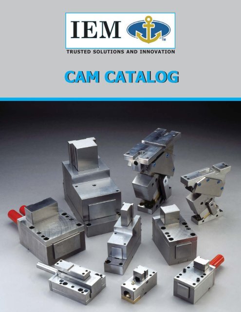
<strong>IEM</strong>www.danly.comCAM CATALOGService We Deliver and Quality You Can Depend On<strong>IEM</strong> is a leading manufacturer of die sets and die component products supplied globally to the partsforming industry. Backed by years of tool and die experience, quality and innovation are some of thereasons why our name is respected throughout the world. We have taken the lead role in creating andbringing new products to customers and helping them find solutions that improve their operations.Based on the capabilities <strong>IEM</strong> offers, we can help you to meet the demands of quick deliveries,technical support, quality products and competitive prices. <strong>IEM</strong> and its broad distribution channelsand direct sales personnel will assist you in any way to make your product a better and moreprofitable one.Whether you purchase on-line or in person, you will receive the same reliable service <strong>IEM</strong> is knownfor. We understand the demanding schedules of die builders and production personnel and havedeveloped efficient manufacturing processes to shorten product lead times as well as put inventoryon our shelves so you can have it in your facility when you need it. Put the <strong>IEM</strong> network to work foryou. We’ve got the service you’ve been looking for.Included in our full line offering are both inch and metric size die sets and die components that aredesigned to numerous die standards including ISO, NAAMS, JIS and many large automotive andappliance manufacturers’ standards. The complete product offering includes:• Ball bearing and friction style die sets including custom and catalog sets• Machined plate• Guide posts & bushings• ISO and JIS Die springs• In-die tapping units for both mechanical and hydraulic presses• Formathane ® Urethane springs, strippers, sheets, bars, rods and die cover film• Diemakers’ supplies such as pry bars, dowel pins, hoist rings, clamps and fasteners• Standard and self-lubricating wear product including wear plate, wear strips, gibs,keeper plates and guide blocks• <strong>Cam</strong> units, including Mini TM , Aerial and Die Mount styles• Accubend TM Rotary Benders• Standard and Ball lock punches and retainers• Air presses• Pad retainers• Nitrogen gas springsOur facility has been Registered by Underwriters Laboratories,Inc. to the International Organization for Standardization ISO9001 Series Standards for Quality.“Registered by UL to ISO 9001.”
ContentsPAGE NUMBER<strong>Cam</strong> Selection MatrixRetainer Mounting MethodsiiivGib <strong>Cam</strong> TM 1Mini <strong>Cam</strong> TM 6Standard <strong>Box</strong> <strong>Cam</strong> 9Maximum Power <strong>Cam</strong> TM (MP) 16<strong>Long</strong> <strong>Reach</strong> <strong>Box</strong> <strong>Cam</strong> 19Custom <strong>Cam</strong>s 25i
<strong>Cam</strong> Selection MatrixGib <strong>Cam</strong> TMMini <strong>Cam</strong> TM<strong>Long</strong> <strong>Reach</strong> <strong>Box</strong>Standard <strong>Box</strong>Max Power TM<strong>Box</strong> (MP)Milfab ®Inch X X X XMetric X X X X X X X X XLow profile X XNarrow width X X XShort length X X X XNDM Die MountsNAAMSStandardsNAC AerialMaximumslide travel X XMaximumstripping force X XNitrogen Return X X X X XPositive return X X X X XMaximumpiercing force X X X X XDesigned toNAAMS Standards X XSpecial <strong>Cam</strong>Designs Available X X X X X X X X X<strong>Long</strong> <strong>Reach</strong>ingDie MountItems inthe blueshadedarea areincludedin thiscatalog.Inch Design – <strong>Cam</strong> is designed around the English or Inchmeasurement standard. Bolt and dowel holes are standard inch components.Metric Design – <strong>Cam</strong> is designed around the Metric measurementstandard. Bolt and dowel holes are standard metric components. (Mayrequire a metric callout when placing an order)Low Profile – The overall height is minimized in a die design. Thelow profile cams are an excellent choice for short press stroke operations,where die space is limited.Narrow Width – Reduces progression space used in a die designwhile allowing multiple standard cams to align side-by-side in a die.ii
<strong>Cam</strong> Selection MatrixShort Length – The short length design is ideal for working at theedge of a die or on the inside of a large part working out. The length ofthe cam is minimized by an internal spring return.Maximum Slide Travel/<strong>Long</strong> <strong>Reach</strong>ing – The slidetravel increases by 30% or more over standard design cams. <strong>Cam</strong>sare good in applications where there is a need to reach over large partflanges or stock material placement limits the proximity of the cam.Maximum Stripping Force – Return spring force is 10% ofworking force. May require Nitrogen Return option.Nitrogen Return – Gas springs are designed into the cam to providehigher stripping forces and even slide return. <strong>Cam</strong>s with nitrogen gassprings will either come standard with a gas spring or may be an optionto replace or use in combination with standard mechanical springs.Positive Return – A mechanical return designed into the cam topull the slide and tooling out of the part. Ideal for applications piercinglarge holes or in sticky materials where there is a chance of die damagedue to a stuck punch.Maximum Piercing Force – Large self lubricated surfaceareas on moving parts provides maximum piercing forces over longextended periods of cam operation.Designed to NAAMS Standards – <strong>Cam</strong>s meet or exceedall of the NAAMS Global Standards for Aerial and Die Mount <strong>Cam</strong> design.SSpecial <strong>Cam</strong> Designs – If a standard cam design doesn’twork for you, then give us your application specifications and we willdesign a special cam for you.iii
Retainer Mounting MethodsSTANDARD RETAINER STANDARD RETAINER STANDARD RETAINERThe soft mounting face ofthe cam slide allows for themounting of a standard lightor heavy duty punch retainer.Oversized retainers work wellif multiple punches are set inan even load pattern in relationto the center of the slide.Off-center loads will reduce theworking tonnage rating of the cam.Multiple retainers easily fit our“double wide” #4L and #14Lcams. Applications requiringoff-center loading of the slidereduces the working tonnagerating of the cam.GANG MOUNTING RETAINERS ON (2) CAMSUsing a bridge block fastened on the slide faceof two of the same cams allows for mounting ofmultiple retainers. Precise timing of both camslides ensures load sharing between the cams.iv
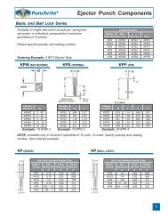
Gib <strong>Cam</strong> TMTechnical InformationProduct FeaturesThe Gib <strong>Cam</strong> is designed to fit into tight spotsto replace the one-of-a-kind made-in-house cams.The low profile slide and gib design glides alonga graphite plugged base plate for continuouslubrication. To ensure the tooling is removedfrom the work piece on every stroke of the press,the slide is powered by a 45° positive returndriver. The Gib <strong>Cam</strong>’s off-the-shelf approachand compact design will make this a camdesigned into dies for years to come.GL-5 Gib <strong>Cam</strong> TMMETRICDESIGNLOWPROFILEPOSITIVERETURNWorking Spring Maximum UnitFace Size Travel Load Rating Force Tool Wt. WeightModel mm/in mm/in kN/tons N/lbs kg/lbs kg/lbsGS-3GM-4GL-5GL-6.535 x 30 24.0 8.9 71.0 1.3 21.38 x 1.18 .94 1 16.0 3.0 5.050 x 40 32 17.8 80.0 1.8 61.97 x 1.57 1.26 2 18.0 4.0 13.060 x 50 40.0 26.7 93.0 2.3 92.36 x 1.97 1.57 3 21.0 5.0 2098 x 50 40.0 53.4 93.2 4.55 133.86 x 1.96 1.57 6 21.0 10 28.6NOTES:♦ Gib <strong>Cam</strong>s TM are hard metric. English conversions are for reference only.♦ The cam slide has .0005" – .001" (0.0127 – .0254mm) clearance betweeneach side of the slide and body to allow for lubrication and heat dissipation.Tighter tolerances are available upon request.Calculated stroke, tonnage and wear curves are presentedas a guideline for design and maintenance only.No warranty exists, either expressed or implied, as a result ofthe application, as it may relate to the information provided.Ask Customer Service for design templates on our website or CD.1
Gib <strong>Cam</strong> TMGS-3All dimensions are for reference onlyand no tolerance is stated or implied.Ask Customer Service for design templates on our website or CD.Gib <strong>Cam</strong>s TM are hard metric.2
Gib <strong>Cam</strong> TMGM-4All dimensions are for reference onlyand no tolerance is stated or implied.Ask Customer Service for design templates on our website or CD.Gib <strong>Cam</strong>s TM are hard metric.3
Gib <strong>Cam</strong> TMGL-5All dimensions are for reference onlyand no tolerance is stated or implied.Ask Customer Service for design templates on our website or CD.Gib <strong>Cam</strong>s TM are hard metric.4
Gib <strong>Cam</strong> TMGL-6.5All dimensions are for reference onlyand no tolerance is stated or implied.Ask Customer Service for design templates on our website or CD.Gib <strong>Cam</strong>s TM are hard metric.5
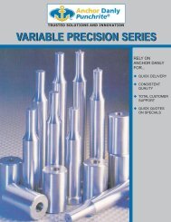
Mini <strong>Cam</strong> TMTechnical InformationSTANDARDUNIT(NO RETAINER)CAM WITH RETAINERHEADED PUNCHBALL LOCK PUNCH101 Mini <strong>Cam</strong> TM101 101H0875 101B250101101H1125 101B375101H1375 –101MM 101H0875MM 101B250MM101MM101H1125MM 101B375MMMETRIC101H1375MM –102 102H1000 102B250102102H1250 102B375102H1500 102B500– 102B625102MM 102H1000MM 102B250MM102MM 102H1250MM 102B375MMMETRIC 102H1500MM 102B500MM– 102B625MMINCHDESIGNMETRICDESIGNNARROWWIDTHSHORTLENGTHCalculated stroke, tonnage and wear curves are presentedas a guideline for design and maintenance only.No warranty exists, either expressed or implied, as a result of theapplication, as it may relate to the information provided.Standard Maximum Approx.Metric Slide Working Spring Tooling <strong>Cam</strong>Models Diameter Travel Load Force Weight Weightin/mm in/mm tons/kN lbs/N lbs/kg lbs/kg101 1.25 .75 2 140 2 8101MM 31.75 19.05 17.8 24.5 0.91 3.63102 1.50 1.00 3 308 2 12102MM 38.10 25.40 26.7 53.9 0.91 5.44NUMBERING EXAMPLE1 0 1 - B - 375Ball Lock Punches<strong>Cam</strong> Unit NumberBody diameter of punch(375 = 3/8")B = Ball Lock Retainer1 0 2 - H - 1250Headed Punches<strong>Cam</strong> Unit NumberLength of retainer(1250 = 1-1/4")H = Headed Punch RetainerRETAINERS FOR BALL LOCK PUNCHESBall-lock punches are widely used in the industrybecause the self-locking feature eliminates the needfor keying the punch. The necessity for sharpening orthe replacement of a broken punch during productionis simplified.Ask Customer Service for design templates on our website or CD.RETAINERS FOR HEADED PUNCHESRetainers for headed punches come in three (3)different lengths for each Mini <strong>Cam</strong> TM unit. Theshortest length retainer comes as a standard for eachunit and will be suitable for most applications.However, some applications may require the use ofa longer retainer. An example might be an applicationin which an exceptionally long punch is used, or whenperforating a heavy material. A longer retainer allowsfor greater stability due to increased gripping range onthe body of the punch.6
Mini <strong>Cam</strong> TM101/101MM Slide Unit<strong>Cam</strong> models are designedin both inch and metric.Listed dimensions may not convertdirectly into the other standard.All dimensions are for reference onlyand no tolerance is stated or implied.Catalog Retainer HeightNumber DimensionwithDRetainer in/mm101H0875 .875 (22.2)101H1125 1.125 (28.6)101H1375 1.375 (34.9)101B250 1.000 (25.4)101B375 1.000 (25.4)Catalog Headed Punches Light DutyNumber Shaped Round Ball Lockwith A B C Point Point PunchesRetainer in/mm in/mm in/mm in in in101H08753/8 .1884 5-7/89.5 4.79 149.23/16 – 1/2 up to 1/2 –101H11255/8 .1884 6-1/815.9 4.79 155.63/16 – 1/2 up to 1/2 –101H13757/8 .1884 6-3/822.2 4.79 161.93/16 – 1/2 up to 1/2 –101B25011/16 .2503 6-3/1617.5 6.36 157.2– – 1/4101B37511/16 .375 6-3/1617.5 9.53 157.2– – 3/8Ask Customer Service for design templates on our website or CD.7
Mini <strong>Cam</strong> TM102/102MM Slide Unit<strong>Cam</strong> models are designedin both inch and metric.Listed dimensions may not convertdirectly into the other standard.All dimensions are for reference onlyand no tolerance is stated or implied.Catalog Retainer HeightNumber DimensionwithDRetainer in/mm102B1000 1.000 (25.4)102B1250 1.250 (31.8)102B1500 1.500 (38.1)102B250 1.000 (25.4)102B375 1.000 (25.4)102B500 1.000 (25.4)102B625 1.000 (25.4)Catalog Headed Punches Light DutyNumber Shaped Round Ball Lockwith A B C Point Point PunchesRetainer in/mm in/mm in/mm in in in102H10001/4 .2509 6 - 3/46.35 6.37 171.51/4 – 5/8 up to 3/4 –102H12501/2 .2509 712.7 6.37 177.81/4 – 5/8 up to 3/4 –102H15003/4 .2509 7 - 1/419.0 6.37 184.21/4 – 5/8 up to 3/4 –102B2501/2 .2503 712.7 6.37 177.8– – 1/4102B3751/2 .3753 712.7 9.53 177.8– – 3/8102B5001/2 .5003 712.7 12.70 177.8– – 1/2102B6251/2 .6253 712.7 15.88 177.8– – 5/8Ask Customer Service for design templates on our website or CD.8
Standard <strong>Box</strong> <strong>Cam</strong>2L External Spring <strong>Box</strong> <strong>Cam</strong>23L Internal Spring <strong>Box</strong> <strong>Cam</strong>4L Double WideExternal Spring <strong>Box</strong> <strong>Cam</strong>INCHDESIGNMETRICDESIGNINCHDESIGNMETRICDESIGNMAXIMUMPIERCINGINCHDESIGNMETRICDESIGNSHORTLENGTHEXTERNAL SPRINGStandard Maximum Approx.<strong>Cam</strong> Face Size Working Spring Tooling <strong>Cam</strong>Models X Travel Load Force Weight Weightin/mm in/mm tons/kN lbs/N lbs/kg lbs/kg2L 1.875 Sq 0.75 2.5 216 5 172LHM 48 Sq 19 22.2 960 2.27 83L 2.5 Sq 1.625 4 444 8 423LHM 63 Sq 42 35.6 1975 3.64 204L 2.75 x 4.75 1.625 8 888 12 784LHM 70 x 121 45 71.2 3950 5.45 365L 3.25 Sq 2.5 7 652 10 935LHM 82 Sq 64 62.3 2900 4.55 43INTERNAL SPRINGStandard Maximum Approx.<strong>Cam</strong> Face Size Working Spring Tooling <strong>Cam</strong>Models X Travel Load Force Weight Weightin/mm in/mm tons/kN lbs/N lbs/kg lbs/kg22L 1.875 Sq .75 2.5 258 5 1522LHM 48 Sq 19 22.2 1148 2.27 33.123L 2.50 Sq 1.625 4 415 8 4123LHM 63 Sq 42 35.6 1846 3.64 90.4Calculated stroke, tonnage and wear curves are presentedas a guideline for design and maintenance only.No warranty exists, either expressed or implied, as a result ofthe application, as it may relate to the information provided.Ask Customer Service for design templates on our website or CD.NOTE:♦ The cam slide has .0005" – .001" (0.0127 – .0254mm)clearance between each side of the slide and body toallow for lubrication and heat dissipation. Tightertolerances are available upon request.9
External Spring <strong>Box</strong> <strong>Cam</strong>2L/2LHM<strong>Cam</strong> models are designedin both inch and metric.Listed dimensions may not convertdirectly into the other standard.All dimensions are for reference onlyand no tolerance is stated or implied.Ask Customer Service for design templates on our website or CD.10
External Spring <strong>Box</strong> <strong>Cam</strong>3L/3LHM<strong>Cam</strong> models are designedin both inch and metric.Listed dimensions may not convertdirectly into the other standard.All dimensions are for reference onlyand no tolerance is stated or implied.Ask Customer Service for design templates on our website or CD.11
External Spring <strong>Box</strong> <strong>Cam</strong> (Double Wide)4L/4LHM<strong>Cam</strong> models are designedin both inch and metric.Listed dimensions may not convertdirectly into the other standard.All dimensions are for reference onlyand no tolerance is stated or implied.Ask Customer Service for design templates on our website or CD.12
External Spring <strong>Box</strong> <strong>Cam</strong>5L/5LHM<strong>Cam</strong> models are designedin both inch and metric.Listed dimensions may not convertdirectly into the other standard.All dimensions are for reference onlyand no tolerance is stated or implied.Ask Customer Service for design templates on our website or CD.13
Internal Spring <strong>Box</strong> <strong>Cam</strong>22L/22LMM<strong>Cam</strong> models are designedin both inch and metric.Listed dimensions may not convertdirectly into the other standard.All dimensions are for reference onlyand no tolerance is stated or implied.Ask Customer Service for design templates on our website or CD.14
Internal Spring <strong>Box</strong> <strong>Cam</strong>23L/23LMM<strong>Cam</strong> models are designedin both inch and metric.Listed dimensions may not convertdirectly into the other standard.All dimensions are for reference onlyand no tolerance is stated or implied.Ask Customer Service for design templates on our website or CD.15
Maximum Power <strong>Cam</strong> TM (MP)24MP Maximum Power <strong>Cam</strong> TMProduct FeaturesThe Maximum Power <strong>Cam</strong> is designed fortight spaces where length and height is limited.It’s a compact high power cam with a maximumworking load for applications requiring piercedholes through thicker steel like automotivechassis frame rails. You will find the bronze wearplates with graphite inserts provide a premiumwear surface for the slide to move along. Themaximum stripping power is derived from acombination mechanical and nitrogen springslide return design. The Maximum Power <strong>Cam</strong>is a cam with everything a large automotive typecam has except the large size.INCHDESIGNMAXIMUMSTRIPPINGNITROGENRETURN OPTIONSHORTLENGTHSpring Maximum Approx.Standard Face Working Force with Tooling <strong>Cam</strong><strong>Cam</strong> Size Travel Load Nitrogen 1 Weight WeightModels in/mm in/mm tons/kN lbs/N lbs/kg lbs/kg24MP24MP-XW3.0 x 4.75 1.625 12 2,141 12 12576 x 120 41.3 106.8 9,516 5.45 56.73.0 x 8.0 1.625 20 3,213 20 18376 x 203 41.3 178 14,280 9.09 83NOTES:1Nitrogen and mechanical spring combination.♦ <strong>Cam</strong> is designed in hard inch. Metric dimensions are for reference only.♦ The cam slide has .0005" – .001" (0.0127 – .0254mm) clearance between each side of the slideand body to allow for lubrication and heat dissipation. Tighter tolerances are available upon request.Calculated stroke, tonnage and wear curves are presentedas a guideline for design and maintenance only.No warranty exists, either expressed or implied, as a result ofthe application, as it may relate to the information provided.Ask Customer Service for design templates on our website or CD.16
Maximum Power <strong>Cam</strong> TM (MP)24MPAll dimensions are for reference onlyand no tolerance is stated or implied.Ask Customer Service for design templates on our website or CD.17
Maximum Power <strong>Cam</strong> TM (MP)24MP-XWAll dimensions are for reference onlyand no tolerance is stated or implied.Ask Customer Service for design templates on our website or CD.18
<strong>Long</strong> <strong>Reach</strong> <strong>Box</strong> <strong>Cam</strong>11L <strong>Long</strong> <strong>Reach</strong> <strong>Box</strong> <strong>Cam</strong>14L Double Wide <strong>Long</strong> <strong>Reach</strong> <strong>Box</strong> <strong>Cam</strong>INCHDESIGNMETRICDESIGNNARROWWIDTHMAXIMUMSLIDE/TRAVELINCHDESIGNMETRICDESIGNMAXIMUMPIERCINGMAXIMUMSLIDE/TRAVELStandard Maximum Approx.<strong>Cam</strong> Face Size Working Spring Tooling <strong>Cam</strong>Models X Travel Load Force Weight Weightin/mm in/mm tons/kN lbs/N lbs/kg lbs/kg11 L 1.875 Sq 2 5 199 4 2911LMM 47.6 Sq 51 44.5 885 1.82 13.1612L 2.125 Sq 2.50 7 314 5 5012LMM 54 Sq 64 62.3 1397 2.27 22.6813L 2.50 Sq 3.25 11 476 8 10013LMM 63.5 Sq 83 97.9 2117 3.64 45.3714L 2.875 x 4.75 3.25 16 952 12 15314LMM 73 x 120.7 83 142.3 4234 5.45 69.4215L 3.25 Sq 3.25 12 738 10 14015LMM 82.6 Sq 83 106.8 3283 4.55 63.52Calculated stroke, tonnage and wear curves are presentedas a guideline for design and maintenance only.No warranty exists, either expressed or implied, as a result ofthe application, as it may relate to the information provided.Ask Customer Service for design templates on our website or CD.NOTE:♦ The cam slide has .0005" – .001" (0.0127 – .0254mm)clearance between each side of the slide and body toallow for lubrication and heat dissipation. Tightertolerances are available upon request.19
<strong>Long</strong> <strong>Reach</strong> <strong>Box</strong> <strong>Cam</strong>11L/11LMM<strong>Cam</strong> models are designedin both inch and metric.Listed dimensions may not convertdirectly into the other standard.All dimensions are for reference onlyand no tolerance is stated or implied.Ask Customer Service for design templates on our website or CD.20
<strong>Long</strong> <strong>Reach</strong> <strong>Box</strong> <strong>Cam</strong>12L/12LMM<strong>Cam</strong> models are designedin both inch and metric.Listed dimensions may not convertdirectly into the other standard.All dimensions are for reference onlyand no tolerance is stated or implied.Ask Customer Service for design templates on our website or CD.21
<strong>Long</strong> <strong>Reach</strong> <strong>Box</strong> <strong>Cam</strong>13L/13LMM<strong>Cam</strong> models are designedin both inch and metric.Listed dimensions may not convertdirectly into the other standard.All dimensions are for reference onlyand no tolerance is stated or implied.Ask Customer Service for design templates on our website or CD.22
<strong>Long</strong> <strong>Reach</strong> <strong>Box</strong> <strong>Cam</strong> (Double Wide)14L/14LMM<strong>Cam</strong> models are designedin both inch and metric.Listed dimensions may not convertdirectly into the other standard.All dimensions are for reference onlyand no tolerance is stated or implied.Ask Customer Service for design templates on our website or CD.23
<strong>Long</strong> <strong>Reach</strong> <strong>Box</strong> <strong>Cam</strong>15L/15LMM<strong>Cam</strong> models are designedin both inch and metric.Listed dimensions may not convertdirectly into the other standard.All dimensions are for reference onlyand no tolerance is stated or implied.Ask Customer Service for design templates on our website or CD.24
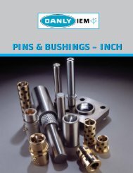
CUSTOM CAMS<strong>IEM</strong>www.danly.comProduct FeaturesAlthough <strong>IEM</strong> has a large offering ofcatalog cams, we realize that in today’scompetitive environment, a catalog camdoesn’t always fit all applications.Custom cams include:♦ <strong>Cam</strong>s engineered by <strong>IEM</strong> specificallyfor your application♦ <strong>Cam</strong>s machined to your design<strong>Cam</strong> design screen printCUSTOM CAM CAPABILITIES:♦ CAM DESIGN‣ <strong>IEM</strong>’s engineering team designs for any application♦ CAM MANUFACTURING‣ <strong>IEM</strong> can build your cam design• Machining – components up to 900mm• Flame hardening with minimal distortionBENEFITS:♦ Frees up your design resources♦ Frees up your machine capacity♦ Provides the best solution for your application♦ Can improve your project scheduling♦ Saves you money as compared to in-house costs♦ Lets you focus on your core competencies25
<strong>IEM</strong>www.danly.comCAM CATALOG<strong>IEM</strong>Distributed by:www.danly.comcams@danly.comWITHIN THE USA & CANADACALL: 800-243-2659FAX: 800-833-2659OUTSIDE THE USA & CANADACALL: 248-489-7816FAX: 248-553-6842© 2007 <strong>IEM</strong>. All rights reserved.DS 401-1 4/07