Operating Dwarf Signal - Lionel
Operating Dwarf Signal - Lionel
Operating Dwarf Signal - Lionel

Create successful ePaper yourself
Turn your PDF publications into a flip-book with our unique Google optimized e-Paper software.
70-2115-250<br />
Rev. A<br />
OPERATING AND LAMP REPLACEMENT INSTRUCTIONS<br />
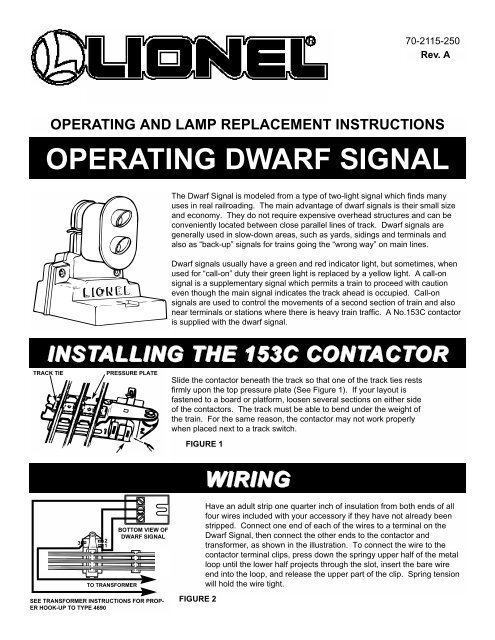
OPERATING DWARF SIGNAL<br />
The <strong>Dwarf</strong> <strong>Signal</strong> is modeled from a type of two-light signal which finds many<br />
uses in real railroading. The main advantage of dwarf signals is their small size<br />
and economy. They do not require expensive overhead structures and can be<br />
conveniently located between close parallel lines of track. <strong>Dwarf</strong> signals are<br />
generally used in slow-down areas, such as yards, sidings and terminals and<br />
also as “back-up” signals for trains going the “wrong way” on main lines.<br />
<strong>Dwarf</strong> signals usually have a green and red indicator light, but sometimes, when<br />
used for “call-on” duty their green light is replaced by a yellow light. A call-on<br />
signal is a supplementary signal which permits a train to proceed with caution<br />
even though the main signal indicates the track ahead is occupied. Call-on<br />
signals are used to control the movements of a second section of train and also<br />
near terminals or stations where there is heavy train traffic. A No.153C contactor<br />
is supplied with the dwarf signal.<br />
INSTALLING THE 153C CONTACTOR<br />
TRACK TIE<br />
PRESSURE PLATE<br />
Slide the contactor beneath the track so that one of the track ties rests<br />
firmly upon the top pressure plate (See Figure 1). If your layout is<br />
fastened to a board or platform, loosen several sections on either side<br />
of the contactors. The track must be able to bend under the weight of<br />
the train. For the same reason, the contactor may not work properly<br />
when placed next to a track switch.<br />
FIGURE 1<br />
WIRING<br />
3<br />
2<br />
1<br />
TO TRANSFORMER<br />
BOTTOM VIEW OF<br />
DWARF SIGNAL<br />
Have an adult strip one quarter inch of insulation from both ends of all<br />
four wires included with your accessory if they have not already been<br />
stripped. Connect one end of each of the wires to a terminal on the<br />
<strong>Dwarf</strong> <strong>Signal</strong>, then connect the other ends to the contactor and<br />
transformer, as shown in the illustration. To connect the wire to the<br />
contactor terminal clips, press down the springy upper half of the metal<br />
loop until the lower half projects through the slot, insert the bare wire<br />
end into the loop, and release the upper part of the clip. Spring tension<br />
will hold the wire tight.<br />
SEE TRANSFORMER INSTRUCTIONS FOR PROP-<br />
ER HOOK-UP TO TYPE 4690<br />
FIGURE 2
ADJUSTING THE CONTACTOR<br />
After all connections are made and the transformer is on, the contactor<br />
must be adjusted so that the <strong>Dwarf</strong> <strong>Signal</strong> operates properly. Stop the<br />
train several sections away from the contactor so that it does not press<br />
on the contactor plate. Turn the adjustment nut just enough to cause<br />
the red light to go out and the green light to go on instead. When properly<br />
adjusted, the contactor will respond to a light finger pressure on the<br />
track and the red light will stay on as long as any part of the train is<br />
passing over the contactor plate. If the action of the two lights is<br />
reversed, interchange connections marked #1 and #2 on the contactor.<br />
FIGURE 3<br />
ADJUSTMENT NUT<br />
ALTERNATE WIRING<br />
If desired, the dwarf signal can be hooked directly to an 0/072 switch.<br />
When the switch is thrown, the signal will automatically change colors.<br />
If you want the opposite light sequence, reverse the two outer leads at<br />
the switch (this hook-up will not work on 027/042 switches).<br />
0/072<br />
SWITCH<br />
UNDERSIDE OF<br />
FIGURE 4<br />
LAMP REPLACEMENT<br />
To remove a lamp, gently pull the lamp cover forward,remove the cover,<br />
and pull the bulb straight out. Do not twist the bulb. Replacement bulbs<br />
are 19-301 red, and 19-302 green. Lamps are available at authorized<br />
<strong>Lionel</strong> Service Stations.<br />
SERVICE<br />
FIGURE 5<br />
This product is proudly offered by <strong>Lionel</strong> Trains, Inc. and it carries a warranty to support itscontinued reliableoperation.<br />
You may choose to have the <strong>Lionel</strong> Service Department service your item even after its warranty expires.If so, a reasonable<br />
service fee will be charged. In either event, please follow the directions below.<br />
If service is required within the warranty period, bring the item to the nearest authorized <strong>Lionel</strong> Trains-Service Center<br />
along with the warranty card. If you prefer to send it back to the factory, you must first write to Customer Service, P.O.<br />
Box 748 New Baltimore, MI 48047-0748 stating what the item is, when it was purchased and what seems to be the problem.<br />
You will be sent a return authorization and a label to assure your merchandise will be properlyhandled upon receipt.<br />
CAUTION: Make sure the item is packed so as to prevent damage to the merchandise. The shipment must beprepaid<br />
and we recommend that it be insured.<br />
Please make sure you have followed the instructions carefully before returning any merchandise for service. This warranty<br />
gives you specific legal rights and you may have others that vary from state to state.