Wiring Diagram of 6A - Lextreme.com
Wiring Diagram of 6A - Lextreme.com
Wiring Diagram of 6A - Lextreme.com

Create successful ePaper yourself
Turn your PDF publications into a flip-book with our unique Google optimized e-Paper software.
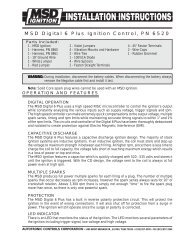
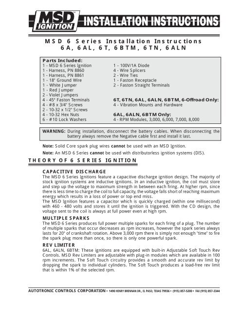
MSD 6 Series Installation Instructions<br />
<strong>6A</strong>, <strong>6A</strong>L, 6T, 6BTM, 6TN, <strong>6A</strong>LN<br />
Parts Included:<br />
1 - MSD 6 Series Ignition 1 - 100V/1A Diode<br />
1 - Harness, PN 8860 4 - Wire Splicers<br />
1 - Harness, PN 8861 2 - Wire Ties<br />
1 - 18" Ground Wire 1 - Faston Receptacle<br />
1 - White Jumper 2 - Faston Straight Terminals<br />
1 - Red Jumper<br />
2 - Violet Jumpers<br />
4 - 45° Faston Terminals 6T, 6TN, <strong>6A</strong>L, <strong>6A</strong>LN, 6BTM, 6-Offroad Only:<br />
4 - #8 x 3/4" Screws 4 - Vibration Mounts and Hardware<br />
2 - 10-32 x 1/2" Screws<br />
4 - 10-32 Hex Nuts <strong>6A</strong>L, <strong>6A</strong>LN, 6BTM Only:<br />
6 - #10 Lock Washers 4 - RPM Modules, 3,000, 6,000, 7,000, 8,000<br />
WARNING: During installation, disconnect the battery cables. When disconnecting the<br />
battery always remove the Negative cable first and install it last.<br />
Note: Solid Core spark plug wires cannot be used with an MSD Ignition.<br />
Note: An MSD 6 Series cannot be used with distributorless ignition systems (DIS).<br />
THEORY OF 6 SERIES IGNITION<br />
CAPACITIVE DISCHARGE<br />
The MSD 6 Series Ignitions feature a capacitive discharge ignition design. The majority <strong>of</strong><br />
stock ignition systems are inductive ignitions. In an inductive ignition, the coil must store<br />
and step up the voltage to maximum strength in between each firing. At higher rpm, since<br />
there is less time to charge the coil to full capacity, the voltage falls short <strong>of</strong> reaching maximum<br />
energy which results in a loss <strong>of</strong> power or top end miss.<br />
The MSD Ignition features a capacitor which is quickly charged (within one millisecond)<br />
with 460 - 480 volts and stores it until the ignition is triggered. With the CD design, the<br />
voltage sent to the coil is always at full power even at high rpm.<br />
MULTIPLE SPARKS<br />
The MSD 6 Series produces full power multiple sparks for each firing <strong>of</strong> a plug. The number<br />
<strong>of</strong> multiple sparks that occur decreases as rpm increases, however the spark series always<br />
lasts for 20° <strong>of</strong> crankshaft rotation. Above 3,000 rpm there is simply not enough "time" to fire<br />
the spark plug more than once, so there is only one powerful spark.<br />
REV LIMITER<br />
<strong>6A</strong>L, <strong>6A</strong>LN, 6BTM: These ignitions are equipped with built-in Adjustable S<strong>of</strong>t Touch Rev<br />
Controls. MSD Rev Limiters are adjustable with plug-in modules which are available in 100<br />
rpm increments. The S<strong>of</strong>t Touch circuitry provides a smooth and accurate rev limit by<br />
dropping the spark to individual cylinders. The S<strong>of</strong>t Touch produces a load-free rev limit<br />
that is within 1% <strong>of</strong> the selected rpm.<br />
AUTOTRONIC CONTROLS CORPORATION • 1490 HENRY BRENNAN DR., EL PASO, TEXAS 79936 • (915) 857-5200 • FAX (915) 857-3344
2 INSTALLATION INSTRUCTIONS<br />
MSD 6T, 6TN<br />
These Ignitions feature a special 4-wire connector which plugs directly into an external rev<br />
limiter; the MSD PN 8738 Rev Control or the S<strong>of</strong>t Touch Engine Control, PN 8968. The<br />
PN 8738 is a single rev limit only, while the PN 8968 features two rev limits and an RPM<br />
Activated Switch.<br />
GENERAL INFORMATION<br />
BATTERY<br />
An MSD 6 Series Ignition Control will operate on any negative ground, 12 volt electrical<br />
system with a distributor. The MSD can be used with 16 volt batteries and can withstand a<br />
momentary 24 volts in case <strong>of</strong> jump starts. The Ignitions will deliver full voltage with a supply<br />
<strong>of</strong> 9 - 18 volts and will operate with a supply voltage as low as five volts.<br />
If your application does not use an alternator, allow at least 15 amp/hour for every half hour<br />
<strong>of</strong> operation. If the engine is cranked with the same battery or other accessories such as an<br />
electric fuel or water pump are used, the amp/hour rating should be higher.<br />
COILS<br />
The MSD 6 Series Ignitions can be used with most stock coils and aftermarket coils designed<br />
to replace the stock coils. There are some "race only" coils such as the MSD Pro Power Coil,<br />
PN 8201, that cannot be used with a 6 Series MSD Ignition Control. For more information<br />
on re<strong>com</strong>mended coils, consult the supplied Coil Application Chart or check with the<br />
manufacturer <strong>of</strong> your coil. If you have any questions concerning coils, contact our Customer<br />
Service Department at (915) 855-7123.<br />
TACHOMETERS<br />
The MSD Ignition features a Tach Output Terminal on the<br />
side <strong>of</strong> the unit. This terminal provides a trigger signal for<br />
tachometers, a shift light or other add-on rpm activated<br />
devices. The Tach Output Terminal produces a 12 volt square<br />
wave signal with a 20% duty cycle.<br />
Some vehicles with factory tachometers may require a Tach<br />
Adapter to operate with the MSD. For more information on<br />
Tachometers and MSD Tach Adapters, see the Tachometer<br />
Section on page 7.<br />
If your GM vehicle has an inline filter it may cause the tach to<br />
drop to zero on acceleration. If this occurs, bypass the filter.<br />
FOREIGN VEHICLES<br />
Figure 1 Tach Terminal<br />
Due to the fuel injection systems, some foreign vehicles may require a special Tach/Fuel<br />
Injection Adapter to use an MSD Ignition. See pages 7 for wiring and Tach Adapter<br />
information.<br />
Note: Vehicles originally equipped with a CD ignition control cannot use an MSD.<br />
SPARK PLUGS AND WIRES<br />
Spark plug wires are very important to the operation <strong>of</strong> your ignition system. A good quality,<br />
helically wound wire and proper routing are required to get the best performance from your<br />
ignition, such as the MSD Heli-Core or 8.5mm Super Conductor Wire.<br />
Note: Solid Core spark plug wires cannot be used with an MSD Ignition.<br />
A helically, or spiral wound wire must be used. This style wire provides a good path for the<br />
spark to follow while keeping Electro Magnetic Interference (EMI) to a minimum. Excessive<br />
EMI, such as the amount that solid core wires produce, will interfere with the operation <strong>of</strong><br />
the MSD.<br />
AUTOTRONIC CONTROLS CORPORATION • 1490 HENRY BRENNAN DR., EL PASO, TEXAS 79936 • (915) 857-5200 • FAX (915) 857-3344
INSTALLATION INSTRUCTIONS 3<br />
Routing: Correct routing <strong>of</strong> the plug wires is also important to performance. Wires should<br />
be routed away from sharp edges and engine heat sources. If there are two wires that are<br />
next to each other in the engine's firing order, the wires should be routed away from each<br />
other to avoid inducing a spark into the other wire. For example, in a Chevy V8, the firing<br />
order is 1-8-4-3-6-5-7-2. The #5 and #7 cylinders are next to each other in the engine and<br />
in the firing order. If the voltage from the #5 wire is induced into #7 detonation could occur<br />
and cause engine damage.<br />
To add more heat protection to your plug wires, MSD <strong>of</strong>fers Pro-Heat Guard, PN 3411. This<br />
is a glass woven and silicone coated protective sleeve that you slide over your plug wires.<br />
For extra protection <strong>of</strong> the spark plug boots, MSD <strong>of</strong>fers Pro-Heat Boot Guard, PN 3412.<br />
Spark Plugs: Choosing the correct spark plug design and heat range is important when<br />
trying to get the best performance possible. Since there are so many engine <strong>com</strong>binations<br />
and manufacturers, MSD does not re<strong>com</strong>mend which plug or gap is exactly right for your<br />
application.<br />
It is re<strong>com</strong>mended to follow the engine builder or manufacturer's specification for spark<br />
plugs. With that, you can then experiment with the plug gap to obtain the best performance.<br />
The gap <strong>of</strong> the plugs can be opened in 0.005" increments, then tested until the best<br />
performance is obtained. MSD judges the plug gap by <strong>com</strong>pression and <strong>com</strong>ponents:<br />
These examples are just staring<br />
points to get you going in the right<br />
direction.Every application is<br />
different and should be tested and<br />
tuned.<br />
Compression Spark Plug Gap<br />
Up to 10.5:1: 0.050" - 0.060"<br />
10.5:1 - 13.0:1: 0.040" - 0.050"<br />
Above 13.0:1: 0.035" - 0.045"<br />
MISCELLANEOUS INFORMATION<br />
Sealing: Do not attempt to seal the MSD. All <strong>of</strong> the circuits <strong>of</strong> an MSD receive a thick<br />
conformal coating <strong>of</strong> Humi-Seal. This sealant protects the electronics from moisture. If you<br />
were to seal the unit, any moisture or water that may seep in through the wiring grommets<br />
will not be able to drain and may result in corrosion.<br />
Welding: If you are welding on your vehicle, to avoid the chance <strong>of</strong> damage, always<br />
disconnect both Heavy Power cables <strong>of</strong> the MSD. (You should also disconnect the tach<br />
ground wire too).<br />
Distributor Cap and Rotor: It is re<strong>com</strong>mended to install a new distributor cap and rotor<br />
when installing the MSD Ignition Control. The cap should be clean inside and out especially<br />
the terminals and rotor tip. On vehicles with smaller caps, it is possible for the air inside the<br />
cap to be<strong>com</strong>e electrically charged causing crossfire which can result in misfire. This can<br />
be prevented by drilling a couple vent holes in the cap. The holes should be placed between<br />
the terminals, at rotor height and face away from the intake. If your environment demands<br />
it, place a small piece <strong>of</strong> screen over the hole to act as a filter.<br />
Initial Spark: It is normal, yet not very <strong>com</strong>mon, for the MSD to produce a spark when the<br />
ignition key is turned On. This is due to the capacitor being charged and if the pickup is in<br />
the right position, it could trigger the ignition momentarily. This could also occur when<br />
installing the positive battery cable.<br />
AUTOTRONIC CONTROLS CORPORATION • 1490 HENRY BRENNAN DR., EL PASO, TEXAS 79936 • (915) 857-5200 • FAX (915) 857-3344
4 INSTALLATION INSTRUCTIONS<br />
MOUNTING<br />
The MSD can be mounted in most positions, except directly upside down (if upside down,<br />
moisture or water cannot escape). It can be mounted in the engine <strong>com</strong>partment as long<br />
as it is away from direct engine heat sources. It is not re<strong>com</strong>mended to mount the unit in an<br />
enclosed area such as the glovebox.<br />
When you find a suitable location to mount the unit, make sure the wires <strong>of</strong> the ignition<br />
reach their connections. Hold the Ignition in place and mark the location <strong>of</strong> the mounting<br />
holes.<br />
• If you have a <strong>6A</strong> Ignition, use an 1/8" drill bit to drill the holes. Use the supplied self<br />
tapping screws to mount the box.<br />
• If you have a <strong>6A</strong>L, 6T, 6BTM, 6-Offroad or "N" Series, use a 3/16" drill bit and drill the holes<br />
for the supplied vibration mounts. Install the vibration mounts, then mount the Ignition.<br />
CYLINDER SELECT<br />
Note: The <strong>6A</strong>, 6T and 6TN do not require any modifications to run on 4 or 6-cylinder even-fire<br />
engines.<br />
The S<strong>of</strong>t Touch Rev Limiter that is built into the MSD <strong>6A</strong>L, 6BTM and <strong>6A</strong>LN is programmed<br />
for operation on a 8-cylinder engine. If you are installing one <strong>of</strong> these units on a 4 or 6-<br />
cylinder even-fire engine, the ignition must be modified. This is easily achieved through the<br />
cylinder select device on the side <strong>of</strong> the ignition. To program the unit:<br />
1. Locate and remove the round black cover with a single Phillips screw.<br />
2. There are two wire loops, a Red and Blue loop. Refer to the chart in Figure 2 to determine<br />
which loop to cut for your application.<br />
3. After cutting the loop(s), turn the wire ends away from each other so they cannot <strong>com</strong>e<br />
into contact. Install the cover and screw.<br />
Note: MSD <strong>of</strong>fers Ignition Controls for odd-fire 6-cylinder engines: <strong>6A</strong>, PN 6246 and the 6T,<br />
PN 6446.<br />
WIRING<br />
Figure 2 Selecting the number <strong>of</strong> Cylinders.<br />
GENERAL WIRING INFORMATION<br />
Wire Length: All <strong>of</strong> the wires <strong>of</strong> the MSD Ignition may be shortened as long as quality<br />
connectors are used or soldered in place. To lengthen the wires, use one size bigger gauge<br />
wire (10 gauge for the power leads and 16 gauge for the other wires) with the proper<br />
connections. All connections must be soldered and sealed.<br />
AUTOTRONIC CONTROLS CORPORATION • 1490 HENRY BRENNAN DR., EL PASO, TEXAS 79936 • (915) 857-5200 • FAX (915) 857-3344
INSTALLATION INSTRUCTIONS 5<br />
Grounds: A poor ground connection can cause many frustrating problems. When a wire is<br />
specified to go to ground, it should be connected to the battery negative terminal, engine<br />
block or chassis. There should always be a ground strap between the engine and the<br />
chassis. Always securely connect the ground wire to a clean, paint free metal surface.<br />
Ballast Resistor: If your vehicle has a ballast resistor in line with the coil wiring, it is not<br />
necessary to bypass it. This is because the MSD receives its main power directly from the<br />
battery.<br />
ROUTING WIRES<br />
The MSD wires should be routed away from direct heat sources such as exhaust manifolds<br />
and headers and any sharp edges. The trigger wires should be routed separate from the<br />
other wires and spark plug wires. It is best if they are routed along a ground plane such as<br />
the block or firewall which creates an electrical shield. The magnetic pickup wires should<br />
always be routed separately and should be twisted together to help reduce extraneous<br />
interference.<br />
WIRE FUNCTIONS<br />
Power Leads<br />
Heavy Red<br />
Heavy Black<br />
Red<br />
Orange<br />
Black<br />
Trigger<br />
Wires<br />
White<br />
Violet<br />
and Green<br />
(Magnetic<br />
Pickup<br />
Connector)<br />
These are the two heavy gauge wires (12 gauge) and are<br />
responsible for getting direct battery voltage to the Ignition. The<br />
ignition has an internal fuse so no fuse is necessary.<br />
This wire connects directly to the battery positive (+) terminal or to<br />
a positive battery junction or the positive side <strong>of</strong> the starter solenoid.<br />
Note: Never connect the alternator.<br />
This wire connects to a good ground, either at the battery negative<br />
(-) terminal or to the engine.<br />
Connects to a switched 12 volt source. Such as the ignition key or switch.<br />
Connects to the positive (+) terminal <strong>of</strong> the coil.<br />
This is the only wire that makes electrical contact with the coil<br />
positive terminal.<br />
Connects to the negative (-) terminal <strong>of</strong> the coil.<br />
This is the only wire that makes electrical contact with the coil<br />
negative terminal.<br />
There are two circuits that can be used to trigger the MSD Ignition;<br />
a Points circuit (White wire) and a Magnetic Pickup circuit (Violet<br />
and Green wires). The two circuits will never be used together.<br />
This wire is used to connect to the points, electronic ignition<br />
amplifier output or to the Yellow wire <strong>of</strong> an MSD Timing Accessory.<br />
When this wire is used, the Magnetic Pickup connector is not used.<br />
These wires are routed together in one harness to form the Magnetic<br />
Pickup connector. The connector plugs directly into an MSD<br />
Distributor or Crank Trigger. It will also connect to factory magnetic<br />
pickups or other aftermarket pickups. The Violet wire is positive (+)<br />
and the Green is negative (-). When these wires are used, the White<br />
wire is not.<br />
AUTOTRONIC CONTROLS CORPORATION • 1490 HENRY BRENNAN DR., EL PASO, TEXAS 79936 • (915) 857-5200 • FAX (915) 857-3344
6 INSTALLATION INSTRUCTIONS<br />
The chart shows the polarity <strong>of</strong> other<br />
<strong>com</strong>mon magnetic pickups. If using<br />
a different magnetic pickup, use the<br />
MSD 2-Pin connector, available as PN<br />
8824, for a direct plug-in installation.<br />
Common Mag Pickup Wires<br />
Distributor<br />
Colors<br />
Mag+ Mag-<br />
MSD Org/Blk Vio/Blk<br />
MSD Crank Trigger Violet Green<br />
Ford Orange Violet<br />
Accel 46/48000 Series Org/Blk Vio/Blk<br />
Accel 51/61000 Series Red Black<br />
Chrysler Org/Wht Black<br />
Mallory Org/Blk Vio/Blk<br />
Figure 3 Common Mag Pickup Wires.<br />
WARNING: The MSD 6 Series Ignitions are capacitive discharge ignitions. High voltage is<br />
present at the coil primary terminals. Do not touch the coil or connect test<br />
equipment to the terminals.<br />
PRESTART CHECK LIST<br />
• The only wires connected to the coil terminals are the MSD Orange to coil positive and<br />
Black to coil negative.<br />
• The small Red wire <strong>of</strong> the MSD is connected to a switched 12 volt source.<br />
• If running a <strong>6A</strong>L, 6BTM or <strong>6A</strong>LN on a 4 or 6-cylinder engine the cylinder select must be<br />
modified.<br />
• The MSD power leads are connected directly to the battery positive and negative terminals.<br />
• The battery is connected and fully charged if not using an alternator.<br />
• The engine is equipped with at least one ground strap to the chassis.<br />
THEFT DETERRENT<br />
The MSD provides the opportunity to easily install a theft deterrent kill switch (Figure 4).<br />
White Wire Trigger<br />
When using the WHITE wire to trigger the MSD, install a switch across the magnetic pickup<br />
VIOLET wire to ground. When the VIOLET wire is grounded, the vehicle will crank but not<br />
start.<br />
Magnetic Pickup Trigger<br />
When using the mag pickup to trigger the MSD, install a switch to the WHITE wire and the<br />
other side to ground. When the WHITE wire is grounded, the vehicle will crank but will not<br />
start.<br />
Figure 4 Connecting a Theft Deterrent Switch Through the MSD Ignition<br />
AUTOTRONIC CONTROLS CORPORATION • 1490 HENRY BRENNAN DR., EL PASO, TEXAS 79936 • (915) 857-5200 • FAX (915) 857-3344
INSTALLATION INSTRUCTIONS 7<br />
TROUBLESHOOTING<br />
Every MSD Ignition undergoes numerous quality control checks including a four hour<br />
burn-in test. If you experience a problem with your MSD, our research has shown that the<br />
majority <strong>of</strong> problems are due to improper installation or poor connections.<br />
The Troubleshooting section has several checks and tests you can perform to ensure proper<br />
installation and operation <strong>of</strong> the MSD. If you have any questions concerning your MSD, call<br />
our Customer Support Department at (915) 855-7123, 8 - 5 mountain time.<br />
TACH/FUEL ADAPTERS<br />
If your tachometer does not operate correctly or if you experience a no-run situation with<br />
your foreign vehicle you probably need an MSD Tach Adapter. The chart in Figure 4 lists<br />
<strong>com</strong>mon tachometers and if an Adapter is necessary.<br />
Tachometer Compatibility List<br />
AFTERMARKET TACHOMETER WHITE WIRE TRIGGER MAGNETIC TRIGGER CONNECTOR<br />
AUTOGAGE 8910 8920<br />
AUTOMETER NONE NONE<br />
FORD MOTORSPORTS NONE NONE<br />
MALLORY NONE NONE<br />
MOROSO NONE NONE<br />
STEWART 8910 8920<br />
S.W. & BI TORX NONE NONE<br />
SUN 8910 8920<br />
VDO 8910 8920<br />
AMC (JEEP) 8910 8920<br />
CHRYSLER 8910 8920<br />
FORD (Before 1976) 8910 8920<br />
FORD (After 1976) 8910 8920<br />
GENERAL MOTORS Bypass In-Line Filter Bypass In-line filter<br />
IMPORTS 8910 8920<br />
Note: On the list above, the trigger wire on tachometers that are marked NONE may be connected to the<br />
Tach Output Terminal on the MSD 6 Series Ignition Unit using the supplied Female Faston Receptacle.<br />
NO-RUN ON FOREIGN VEHICLES<br />
Some foreign vehicles with fuel injection systems may require an MSD Tach/Fuel Injection<br />
Adapter to run with an MSD 6 Series Ignition. This is because many <strong>of</strong> these systems use<br />
the same trigger source to operate the MSD, the tachometer and the fuel injection. This<br />
results in a voltage signal that is too low to accurately trigger the fuel injection. To fix this, an<br />
MSD Tach Adapter, PN 8910, will usually remedy the problem.<br />
Note: If the PN 8910 does not fix the problem, a special Tach Adapter may be required.<br />
Toyotas and Ford Probes may require these special adapters. If you experience this,<br />
call MSD Customer Support for the correct Adapter for your application.<br />
INOPERATIVE TACHOMETERS<br />
If your tachometer fails to operate with the MSD installed you may need an MSD Tach<br />
Adapter. Before getting an Adapter, try connecting your tachometer trigger wire to the tach<br />
output terminal on the side <strong>of</strong> the MSD. This output produces a 12 volt, square wave (see<br />
page 2). If the tach still does not operate, you will need a Tach Adapter. There are two Tach<br />
Adapters:<br />
PN 8920: If you are using the Magnetic Pickup connector (Green and Violet wires) to trigger<br />
the MSD, you will need the PN 8920.<br />
AUTOTRONIC CONTROLS CORPORATION • 1490 HENRY BRENNAN DR., EL PASO, TEXAS 79936 • (915) 857-5200 • FAX (915) 857-3344
8 INSTALLATION INSTRUCTIONS<br />
PN 8910: If your tachometer was triggered from the coil negative terminal (voltage trigger)<br />
and you are using the White wire to trigger the MSD you will need the PN 8910.<br />
BALLAST RESISTOR<br />
If you have a current trigger tach<br />
(originally coil positive) and use the<br />
White wire <strong>of</strong> the MSD, you can<br />
purchase a Chrysler Dual Ballast<br />
Resistor (used from 1973 - 1976) and<br />
wire it as shown in Figure 5.<br />
Figure 5 <strong>Wiring</strong> the Dual Ballast Resistor<br />
ENGINE RUN-ON<br />
If your engine continues to run even when the ignition is turned Off you are experiencing<br />
engine Run-On. This usually only occurs on older vehicles with an external voltage regulator.<br />
Because the MSD receives power directly from the battery, it does not require much current<br />
to keep the unit energized. If you are experiencing run-on, it is due to a small amount <strong>of</strong><br />
voltage going through the charging lamp indicator and feeding the small Red wire even if<br />
the key is turned <strong>of</strong>f.<br />
Early Ford and GM: To solve the Run-On problem, a Diode is supplied with the MSD in the<br />
parts bag. By installing this Diode in-line <strong>of</strong> the wire that goes to the Charging indicator, the<br />
voltage is kept from entering the MSD. Figure 6 shows the proper installation for early Ford<br />
and GM vehicles.<br />
Note:Diodes are used to allow voltage to flow only one way. Make sure the Diode is installed<br />
facing the proper direction (as shown in Figure 6).<br />
Ford: Install the Diode inline to the wire going to the #1 terminal.<br />
GM: Install the Diode in-line to the wire going to terminal #4.<br />
Figure 6 Installing the Diode to fix Run-On.<br />
GM 1973 - 1983 with Delcotron Alternators<br />
GM Delcotron Alternators use an internal voltage regulator. Install the Diode in-line on the<br />
smallest wire exiting the alternator (Figure 6). It is usually a Brown wire.<br />
AUTOTRONIC CONTROLS CORPORATION • 1490 HENRY BRENNAN DR., EL PASO, TEXAS 79936 • (915) 857-5200 • FAX (915) 857-3344
INSTALLATION INSTRUCTIONS 9<br />
Most other applications: On<br />
other applications where<br />
engine Run-On is experienced,<br />
a Resistor can be put in-line to<br />
the MSD's small Red wire<br />
(Figure 7). This resistor will<br />
keep voltage from leaking<br />
through to the MSD unit.<br />
MISSES AND INTERMITTENT PROBLEMS<br />
Experience at the races has shown that if your engine is experiencing a miss or hesitation at<br />
higher rpm, it is usually not directly ignition. Most probable causes include a coil or plug<br />
wire failure, arcing from the cap or boot plug to ground or spark ionization inside the cap.<br />
Several items to inspect are:<br />
• Always inspect the plug wires at the cap and at the plug for a tight connection and visually<br />
inspect for cuts, abrasions or burns.<br />
• Inspect the Primary Coil Wire connections. Because the MSD is a Capacitive Discharge<br />
ignition and it receives a direct 12 volt source from the battery, there will not be any voltage<br />
at the Coil Positive (+) terminal even with the key turned On. During cranking or while the<br />
engine is running, very high voltage will be present and no test equipment should be<br />
connected.<br />
WARNING: Do not touch the coil terminals during cranking or while the engine is running.<br />
• Make sure that the battery is fully charged and the connections are clean and tight. If you<br />
are not running an alternator this is an imperative check. If the battery voltage falls below<br />
10 volts during a race, the MSD output voltage will drop.<br />
• Is the engine running lean? Inspect the spark plugs and <strong>com</strong>plete fuel system.<br />
• Inspect all wiring connections for corrosion or damage. Remember to always use proper<br />
connections followed by soldering and seal the connections <strong>com</strong>pletely.<br />
If everything checks positive, use the following procedure to test the ignition for spark. MSD<br />
also <strong>of</strong>fers an Ignition Tester, PN 8995. This tool allows you to check your <strong>com</strong>plete ignition<br />
system while it is in the car as well as the operation <strong>of</strong> rpm limits, activated switches and shift<br />
lights.<br />
CHECKING FOR SPARK<br />
Figure 7 <strong>Wiring</strong> the Dual Ballast Resistor for Run-On.<br />
If triggering the ignition with the White wire:<br />
WHITE WIRE TRIGGER<br />
1. Make sure the ignition switch is in the "Off"<br />
position.<br />
2. Remove the coil wire from the distributor cap<br />
and set the terminal approximately 1/2" from<br />
ground.<br />
3. Disconnect the MSD White wire from the<br />
distributor's points or ignition amplifier. Figure 8 Checking for Spark with the White Wire.<br />
4. Turn the ignition to the On position. Do not crank the engine.<br />
AUTOTRONIC CONTROLS CORPORATION • 1490 HENRY BRENNAN DR., EL PASO, TEXAS 79936 • (915) 857-5200 • FAX (915) 857-3344
10 INSTALLATION INSTRUCTIONS<br />
5. Tap the White wire to ground several times. Each time you pull the wire from ground, a<br />
spark should jump from the coil wire to ground. If spark is present, the ignition is working<br />
properly. If there is no spark skip to step 6 below:<br />
If triggering with the Magnetic Pickup:<br />
MAGNETIC PICKUP TRIGGER<br />
1. Make sure the ignition switch is in the "Off"<br />
position.<br />
2. Remove the coil wire from the distributor cap<br />
and set the terminal approximately 1/2" from<br />
ground.<br />
3. Disconnect the MSD magnetic pickup wires<br />
from the distributor.<br />
4. Turn the ignition to the On position. Do not Figure 9 Checking for Spark with Magnetic<br />
crank the engine.<br />
Pickup.<br />
5. With a small jumper wire, short the MSD's Green and Violet magnetic pickup wires<br />
together. Each time you break this short, a spark should jump from the coil wire to<br />
ground. If spark is present, the ignition is working properly. If there is no spark skip to<br />
step 6 below:<br />
6. If there is no spark:<br />
A. Inspect all <strong>of</strong> the wiring.<br />
B. Substitute another coil and repeat the test. If there is now spark, the coil is at fault.<br />
C. If there is still no spark, check to make sure there is 12 volts on the small Red wire<br />
from the MSD when the key is in the On position. If 12 volts is not present, find<br />
another switched 12 volt source and repeat the test.<br />
D. If, after following the test procedures and inspecting all <strong>of</strong> the wiring, there is still<br />
no spark, the MSD Ignition is in need <strong>of</strong> repair. See the Warranty and Service<br />
section for information.<br />
The following wiring diagrams illustrate numerous installations on different vehicles and<br />
applications. If you experience difficulties when installing your MSD, contact our Customer<br />
Support Department at (915) 855-7123 (8 - 5 Mountain time) or e-mail us at:<br />
msdtech@msdignition.<strong>com</strong><br />
MSD SYSTEMS Installing to Points/Amplifier Style Ignition.<br />
NOTE: On dual point setups, it is re<strong>com</strong>mended<br />
to remove the trailing set <strong>of</strong> points.<br />
NOTE: Ballast Resistor is not necessary.<br />
AUTOTRONIC CONTROLS CORPORATION • 1490 HENRY BRENNAN DR., EL PASO, TEXAS 79936 • (915) 857-5200 • FAX (915) 857-3344
INSTALLATION INSTRUCTIONS 11<br />
MSD SYSTEMS<br />
Installing to an MSD Distributor/Crank Trigger.<br />
MSD SYSTEMS Installing to an MSD Distributor PN 8360.<br />
NOTE: The ignition module <strong>of</strong> the PN 8360<br />
still triggers the MSD.<br />
AUTOTRONIC CONTROLS CORPORATION • 1490 HENRY BRENNAN DR., EL PASO, TEXAS 79936 • (915) 857-5200 • FAX (915) 857-3344
12 INSTALLATION INSTRUCTIONS<br />
MSD SYSTEMS Installing to an MSD Distributor PN 8460.<br />
NOTE: The PN 8460 distributor has been discontinued.<br />
MSD SYSTEMS With an MSD Timing Control (points or amplifier).<br />
AUTOTRONIC CONTROLS CORPORATION • 1490 HENRY BRENNAN DR., EL PASO, TEXAS 79936 • (915) 857-5200 • FAX (915) 857-3344
INSTALLATION INSTRUCTIONS 13<br />
MSD SYSTEMS<br />
Typical Drag Race Setup with Timing Control and Two Step Selector.<br />
MSD SYSTEMS <strong>Wiring</strong> Dual MSD's with PN 8301 Switch.<br />
AUTOTRONIC CONTROLS CORPORATION • 1490 HENRY BRENNAN DR., EL PASO, TEXAS 79936 • (915) 857-5200 • FAX (915) 857-3344
14 INSTALLATION INSTRUCTIONS<br />
MSD SYSTEMS<br />
<strong>Wiring</strong> a Complete Dual MSD Ignition Setup.<br />
GM IGNITIONS <strong>Wiring</strong> a Dual Connector Coil.<br />
NOTE: MSD <strong>of</strong>fers a direct plug in harness,<br />
PN 8876, for this coil.<br />
NOTE: Cut and splice the two pink wires (coil<br />
positive) together and connect to orange<br />
wire <strong>of</strong> MSD. Cut and splice the two white<br />
wires (coil negative) together and<br />
connect to the white <strong>of</strong> MSD. If the vehicle<br />
is not equipped with a factory tach, there<br />
will only be one white wire.<br />
AUTOTRONIC CONTROLS CORPORATION • 1490 HENRY BRENNAN DR., EL PASO, TEXAS 79936 • (915) 857-5200 • FAX (915) 857-3344
INSTALLATION INSTRUCTIONS 15<br />
GM IGNITIONS<br />
<strong>Wiring</strong> the 1996 and up single connector coil without harness.<br />
NOTE: MSD <strong>of</strong>fers a direct plug in harness that<br />
makes this a splice free installation.<br />
Harness PN 8877 - 1996-on GM Vehicles.<br />
NOTE: The coil connector is labeled A-B-C. The wire in the A<br />
port is positive (pink). The wires in B and C are coil<br />
negative wires, color will vary by application.<br />
GM IGNITIONS<br />
<strong>Wiring</strong> with an MSD <strong>Wiring</strong> Harness.<br />
Harness PN 8876 - Dual Connector Coil.<br />
Harness PN 8877 - 1996-on GM Vehicles.<br />
AUTOTRONIC CONTROLS CORPORATION • 1490 HENRY BRENNAN DR., EL PASO, TEXAS 79936 • (915) 857-5200 • FAX (915) 857-3344
16 INSTALLATION INSTRUCTIONS<br />
GM IGNITIONS <strong>Wiring</strong> with an MSD <strong>Wiring</strong> Harness and a Timing Control.<br />
Harness PN 8876 - Dual Connector Coil.<br />
Harness PN 8877 - 1996-on GM Vehicles.<br />
GM IGNITIONS<br />
GM Large Cap HEI Distributors<br />
There are three different large cap HEI distributors. To indentify<br />
which <strong>of</strong> the following diagrams fit you specific application, remove<br />
the distributor cap and rotor and locate the ignition module at the<br />
base <strong>of</strong> the distributor. Count the number <strong>of</strong> terminals on both ends<br />
<strong>of</strong> the module and follow the corresponding diagram. GM used 4, 5,<br />
and 7-pin modules in these distributors.<br />
NOTE: Some 5-pin models may experience a hesitation or stall on<br />
decceleration. If this occurs, contact MSD Tech Line for the<br />
required bolt-in diode to correct the problem. MSD Tech<br />
Line (915) 855-7123<br />
AUTOTRONIC CONTROLS CORPORATION • 1490 HENRY BRENNAN DR., EL PASO, TEXAS 79936 • (915) 857-5200 • FAX (915) 857-3344
INSTALLATION INSTRUCTIONS 17<br />
GM IGNITIONS <strong>Wiring</strong> an HEI 4-pin Module (Magnetic Pickup Trigger).<br />
NOTE: The GM Ignition Module is removed and replaced<br />
with the MSD PN 8861 Wire Harness.<br />
GM IGNITIONS<br />
<strong>Wiring</strong> an HEI 5 or 7-pin Module (Amplifier Trigger).<br />
NOTE: Some 5-pin models may experience a<br />
hesitation or stall on decceleration. If this<br />
occurs, contact MSD Tech Line for the<br />
required bolt-in diode to correct the<br />
problem. MSD Tech Line (915) 855-7123.<br />
AUTOTRONIC CONTROLS CORPORATION • 1490 HENRY BRENNAN DR., EL PASO, TEXAS 79936 • (915) 857-5200 • FAX (915) 857-3344
18 INSTALLATION INSTRUCTIONS<br />
FORD IGNITIONS<br />
<strong>Wiring</strong> a Ford DuraSpark using White Wire Trigger.<br />
FORD IGNITIONS <strong>Wiring</strong> a Ford DuraSpark using Magnetic Pickup Trigger.<br />
NOTE: MSD Offers a harness, PN 8869 to connect the magnetic<br />
pickup connector to the Ford Duraspark connector.<br />
AUTOTRONIC CONTROLS CORPORATION • 1490 HENRY BRENNAN DR., EL PASO, TEXAS 79936 • (915) 857-5200 • FAX (915) 857-3344
INSTALLATION INSTRUCTIONS 19<br />
FORD IGNITIONS<br />
<strong>Wiring</strong> a Ford TFI (without Harness).<br />
FORD IGNITIONS <strong>Wiring</strong> a Ford TFI with Harness, PN 8874.<br />
NOTE: Installation <strong>of</strong> a Timing Control with the Harness, see page 16.<br />
AUTOTRONIC CONTROLS CORPORATION • 1490 HENRY BRENNAN DR., EL PASO, TEXAS 79936 • (915) 857-5200 • FAX (915) 857-3344
20 INSTALLATION INSTRUCTIONS<br />
CHRYSLER IGNITIONS<br />
<strong>Wiring</strong> a Chrysler Electronic Ignition using Magnetic Pickup Trigger.<br />
CHRYSLER IGNITIONS <strong>Wiring</strong> a Late Model Dodge with 2-pin connector.<br />
AUTOTRONIC CONTROLS CORPORATION • 1490 HENRY BRENNAN DR., EL PASO, TEXAS 79936 • (915) 857-5200 • FAX (915) 857-3344
INSTALLATION INSTRUCTIONS 21<br />
CHRYSLER IGNITIONS<br />
<strong>Wiring</strong> a Jeep with Integrated Coil/Module Assembly.<br />
MSD <strong>of</strong>fers a <strong>Wiring</strong> Kit, PN 8813, that allows you to modify the original Jeep Ignition<br />
Module/Coil assembly. This style <strong>of</strong> ignition is used in many 1987-1989 models. The<br />
drawing shows the installation with the coil already modified.<br />
HONDA IGNITIONS <strong>Wiring</strong> a Honda with Internal Coil.<br />
AUTOTRONIC CONTROLS CORPORATION • 1490 HENRY BRENNAN DR., EL PASO, TEXAS 79936 • (915) 857-5200 • FAX (915) 857-3344
22 INSTALLATION INSTRUCTIONS<br />
HONDA<br />
<strong>Wiring</strong><br />
IGNITIONS<br />
a Toyota with<br />
<strong>Wiring</strong><br />
a Tach<br />
a Honda<br />
Adapt<br />
with<br />
PN 8910HEI.<br />
a Blaster Coil and Power Cap.<br />
NOTE: MSD <strong>of</strong>fers a Power Cap to convert your<br />
internal coil Honda to external coil for most<br />
popular models.<br />
GENERAL IMPORT WIRING<br />
NOTE: Remove the coil<br />
terminal wires. The<br />
negative wire connects to<br />
MSD White. The positive<br />
wire connects to MSD<br />
Red. The MSD Orange<br />
connects to the coil<br />
positive terminal, Black<br />
connects to the coil<br />
negative terminal.<br />
AUTOTRONIC CONTROLS CORPORATION • 1490 HENRY BRENNAN DR., EL PASO, TEXAS 79936 • (915) 857-5200 • FAX (915) 857-3344
INSTALLATION INSTRUCTIONS 23<br />
AFTERMARKET COMPONENTS <strong>Wiring</strong> a Mallory 9000 Series using Magnetic Pickup.<br />
AFTERMARKET COMPONENTS <strong>Wiring</strong> a Mallory Unilite or 9000 Series using Points Trigger.<br />
<strong>Wiring</strong> a Toyota with a Tach Adapt PN 8910HEI.<br />
AUTOTRONIC CONTROLS CORPORATION • 1490 HENRY BRENNAN DR., EL PASO, TEXAS 79936 • (915) 857-5200 • FAX (915) 857-3344
AFTERMARKET COMPONENTS <strong>Wiring</strong> to a Pertronix Ignitor Kit<br />
If you did not find a schematic to match your application, or if you need assistance, please<br />
contact MSD Tech at (915) 855-7123.<br />
Service<br />
In case <strong>of</strong> malfunction, this MSD <strong>com</strong>ponent will be repaired free <strong>of</strong> charge according to the<br />
terms <strong>of</strong> the warranty. When returning MSD <strong>com</strong>ponents for service, Pro<strong>of</strong> <strong>of</strong> Purchase must be<br />
supplied for warranty verification. After the warranty period has expired, repair service is charged<br />
based on a minimum and maximum charge.<br />
Send the unit prepaid with pro<strong>of</strong> <strong>of</strong> purchase to the attention <strong>of</strong>: Customer Service Department,<br />
Autotronic Controls Corporation, 12120 Esther Lama, Suite 114, El Paso, Texas 79936.<br />
When returning the unit for repair, leave all wires at the length in which you have them installed.<br />
Be sure to include a detailed account <strong>of</strong> any problems experienced, and what <strong>com</strong>ponents and<br />
accessories are installed on the vehicle.<br />
The repaired unit will be returned as soon as possible after receipt, COD for any charges. (Ground<br />
shipping is covered by warranty). All units are returned regular UPS unless otherwise noted. For<br />
more information, call the MSD Customer Service Line (915) 855-7123. MSD technicians are available<br />
from 8:00 a.m. to 5:00 p.m. Monday - Friday (mountain time).<br />
Limited Warranty<br />
Autotronic Controls Corporation warrants MSD Ignition products to be free from defects in material<br />
and workmanship under normal use and if properly installed for a period <strong>of</strong> one year from date <strong>of</strong><br />
purchase. If found to be defective as mentioned above, it will be replaced or repaired if returned prepaid<br />
along with pro<strong>of</strong> <strong>of</strong> date <strong>of</strong> purchase. This shall constitute the sole remedy <strong>of</strong> the purchaser and the sole<br />
liability <strong>of</strong> Autotronic Controls Corporation. To the extent permitted by law, the foregoing is exclusive<br />
and in lieu <strong>of</strong> all other warranties or representations whether expressed or implied, including any implied<br />
warranty <strong>of</strong> merchantability or fitness. In no event shall Autotronic Controls Corporation be liable for<br />
special or consequential damages.<br />
AUTOTRONIC CONTROLS CORPORATION • 1490 HENRY BRENNAN DR., EL PASO, TEXAS 79936 • (915) 857-5200 • FAX (915) 857-<br />
FRM21992 Revised 08/00 Printed In U.S.A.