CPC-PCI/SJA1000 User Manual - Ems-wuensche.com
CPC-PCI/SJA1000 User Manual - Ems-wuensche.com
CPC-PCI/SJA1000 User Manual - Ems-wuensche.com

You also want an ePaper? Increase the reach of your titles
YUMPU automatically turns print PDFs into web optimized ePapers that Google loves.
CAN-PC Interface<br />
<strong>CPC</strong>-<strong>PCI</strong><br />
<strong>User</strong> manual<br />
EMS<br />
Thomas Wünsche
<strong>User</strong> <strong>Manual</strong><br />
<strong>CPC</strong>-<strong>PCI</strong><br />
<strong>User</strong> manual <strong>CPC</strong>-<strong>PCI</strong> V2<br />
Document version: 2.03<br />
Documentation date: October 07th, 2009<br />
No part of this document or the software described herein may be<br />
reproduced in any form without prior written agreement from EMS Dr.<br />
Thomas Wünsche.<br />
For technical assistance please contact:<br />
EMS Dr. Thomas Wünsche<br />
Sonnenhang 3<br />
D-85304 Ilmmünster<br />
Tel. +49-8441-490260<br />
Fax +49-8441-81860<br />
Our products are continously improved. Due to this fact specifications may<br />
be changed at any time and without announcement.<br />
WARNING:<br />
<strong>CPC</strong>-<strong>PCI</strong> hardware and software may not be used in<br />
applications where damage to life, health or private<br />
property may result from failures in or caused by<br />
these <strong>com</strong>ponents.<br />
2 EMS Dr. Thomas Wünsche
<strong>CPC</strong>-<strong>PCI</strong><br />
<strong>User</strong> <strong>Manual</strong><br />
Content<br />
1 Overview 4<br />
1.1 Attributes 4<br />
1.2 General Description 4<br />
1.3 Ordering Information 5<br />
2 Programming Interface 6<br />
3 Electrical Characteristics 7<br />
3.1 Absolute Limiting Values 7<br />
3.2 Nominal Values 7<br />
4. Operating Instructions 8<br />
4.1 Pin Configuration of CAN Connector 8<br />
4.2 Configuration 8<br />
4.3 Installation 9<br />
EMS Dr. Thomas Wünsche<br />
3
<strong>User</strong> <strong>Manual</strong><br />
<strong>CPC</strong>-<strong>PCI</strong><br />
1 Overview<br />
1.1 Attributes<br />
• CAN Interfaces for industrial applications<br />
• Compact size for <strong>PCI</strong> slots<br />
• CiA DS 102 and ISO 11898 <strong>com</strong>patible physical layer<br />
• Equipped with up to four CAN controller NXP <strong>SJA1000</strong><br />
• Galvanic decoupling between PC and CAN bus (optional)<br />
• Galvanic decoupling between individual CAN channels (optional)<br />
• Easy programming based on direct mapping of CAN controller<br />
registers into PC memory area<br />
1.2 General Description<br />
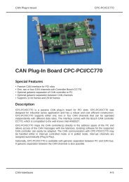
<strong>CPC</strong>-<strong>PCI</strong> is a <strong>PCI</strong> plug-in card for the CAN bus. Designed for<br />
industrial series applications <strong>CPC</strong>-<strong>PCI</strong> has a robust and cost efficient<br />
layout. <strong>CPC</strong>-<strong>PCI</strong> supports up to four CAN controller of type NXP<br />
<strong>SJA1000</strong>.<br />
<strong>CPC</strong>-<strong>PCI</strong> maps the CAN controller into the PC address space and<br />
thus allows access to CAN messages with low latency. Existing<br />
software for the supported CAN controller can easily be adapted.<br />
With <strong>CPC</strong>-<strong>PCI</strong> the CAN <strong>com</strong>munication may be handled either in<br />
interrupt controlled or in polled mode.<br />
<strong>CPC</strong>-<strong>PCI</strong> can optionally be delivered with galvanic decoupling of the<br />
CAN bus. The dual and four channel version has the additional<br />
option of galvanic decoupling between the CAN channels.<br />
4 EMS Dr. Thomas Wünsche
<strong>CPC</strong>-<strong>PCI</strong><br />
<strong>User</strong> <strong>Manual</strong><br />
1.3 Ordering Information<br />
10-05-200-20 <strong>CPC</strong>-<strong>PCI</strong>/<strong>SJA1000</strong>S<br />
CAN plug-in board with one CAN controller<br />
NXP <strong>SJA1000</strong><br />
10-05-201-20 <strong>CPC</strong>-<strong>PCI</strong>/<strong>SJA1000</strong>S-GTIS<br />
CAN plug-in board with one CAN controller<br />
NXP <strong>SJA1000</strong>, galvanic decoupling<br />
10-05-210-20 <strong>CPC</strong>-<strong>PCI</strong>/<strong>SJA1000</strong>D<br />
CAN plug-in board with two CAN controllers<br />
NXP <strong>SJA1000</strong><br />
10-05-211-20 <strong>CPC</strong>-<strong>PCI</strong>/<strong>SJA1000</strong>D-GTID<br />
CAN plug-in board with two CAN controllers<br />
NXP <strong>SJA1000</strong>, galvanic decoupling<br />
10-05-212-20 <strong>CPC</strong>-<strong>PCI</strong>/<strong>SJA1000</strong>D-GTI2S<br />
CAN plug-in board with two CAN controllers<br />
NXP <strong>SJA1000</strong>, individual galvanic decoupling<br />
10-05-230-20 <strong>CPC</strong>-<strong>PCI</strong>/<strong>SJA1000</strong>Q<br />
CAN plug-in board with four CAN controllers<br />
NXP <strong>SJA1000</strong><br />
10-05-231-20 <strong>CPC</strong>-<strong>PCI</strong>/<strong>SJA1000</strong>Q-GTI<br />
CAN plug-in board with four CAN controllers<br />
NXP <strong>SJA1000</strong>, galvanic decoupling<br />
10-05-232-20 <strong>CPC</strong>-<strong>PCI</strong>/<strong>SJA1000</strong>Q-GTIS<br />
CAN plug-in board with four CAN controllers<br />
NXP <strong>SJA1000</strong>, individual galvanic decoupling<br />
EMS Dr. Thomas Wünsche<br />
5
<strong>User</strong> <strong>Manual</strong><br />
<strong>CPC</strong>-<strong>PCI</strong><br />
2 Programming Interface<br />
<strong>CPC</strong>-<strong>PCI</strong> is mapped into the PC memory space with a base address<br />
assigned by the PC BIOS. The availability of the CAN controller(s)<br />
int the memory area makes the CAN <strong>com</strong>munication direct and<br />
provides a low latency time. The card is identified by the following<br />
parameters:<br />
Vendor ID<br />
Device ID<br />
Subvendor ID<br />
Subsystem ID<br />
: 0x10B5<br />
: 0x9030<br />
: 0x10B5<br />
: 0x4000<br />
<strong>CPC</strong>-<strong>PCI</strong> incorporates a PLX9030 <strong>PCI</strong> to local bus bridge. BAR0 of<br />
the <strong>PCI</strong> configuration space register points to the bridge registers,<br />
whereas BAR2 plus an offset of 0x400 points to the first <strong>SJA1000</strong><br />
CAN controller. At offset 0x600, 0x800 and 0xA00 of BAR2 the<br />
optional second, third and fourth <strong>SJA1000</strong> CAN controller can be<br />
accessed.<br />
Please contact EMS Dr. Thomas Wünsche for more detailed<br />
information about the programming interface of <strong>CPC</strong>-<strong>PCI</strong>.<br />
6 EMS Dr. Thomas Wünsche
<strong>CPC</strong>-<strong>PCI</strong><br />
<strong>User</strong> <strong>Manual</strong><br />
3 Electrical Characteristics<br />
3.1 Absolute Limiting Values<br />
Any (also temporary) stress in excess of the limiting values may<br />
cause permanent damage on <strong>CPC</strong>-<strong>PCI</strong> and connected devices.<br />
Parameter Min. Max. Unit<br />
Storage temperature -20 80 °C<br />
Operating temperature* 0 60 °C<br />
Voltage on the bus connections -30 30 V<br />
Current across ground connection - 1 A<br />
* Extended temperature range on demand<br />
3.2 Nominal Values<br />
Parameter Min. Typ. Max. Unit<br />
Power supply on +5V Pins of<br />
the <strong>PCI</strong> expansion slot<br />
4.75 5.00 5.25 V<br />
Voltage on bus pins* -30 - 30 V<br />
CAN controller clock frequency - 16 - MHz<br />
* This potential is measured against the ground potential of the related CAN<br />
transceiver<br />
EMS Dr. Thomas Wünsche<br />
7
<strong>User</strong> <strong>Manual</strong><br />
<strong>CPC</strong>-<strong>PCI</strong><br />
4 Operating Instructions<br />
4.1 Pin configuration of CAN connector<br />
The CAN interface connector (D-Sub 9 male) schema <strong>com</strong>plies to<br />
CiA Standard DS 102. The pin usage is detailed in the following<br />
table:<br />
Pin Name Description<br />
1 -<br />
Reserved by CiA, not connected<br />
2 CAN_L CAN low bus line<br />
3 GND CAN Ground<br />
4 -<br />
Reserved by CiA, not connected<br />
5 -<br />
Reserved by CiA, not connected<br />
6 -<br />
Reserved by CiA, not connected<br />
7 CAN_H CAN high bus line<br />
8 -<br />
Reserved by CiA, not connected<br />
9 -<br />
Reserved by CiA, not connected<br />
4.2 Configuration<br />
<strong>CPC</strong>-<strong>PCI</strong> is a Plug and Play interface and therefore does not need a<br />
configuration. The base address of the interface within the PC<br />
memory and the interrupt used is assigned by the PC BIOS.<br />
8 EMS Dr. Thomas Wünsche
<strong>CPC</strong>-<strong>PCI</strong><br />
<strong>User</strong> <strong>Manual</strong><br />
4.3 Installation<br />
<strong>CPC</strong>-<strong>PCI</strong> may be installed in an empty expansion slot on the<br />
motherboard of your IBM <strong>com</strong>patible <strong>com</strong>puter. To avoid damage<br />
please pay attention to the following hints:<br />
WARNING: Computer devices and <strong>com</strong>ponents are sensitive<br />
against static discharge. For this reason keep <strong>CPC</strong>-<strong>PCI</strong> in the<br />
antistatic cover until installing. Just before removing <strong>CPC</strong>-<strong>PCI</strong> from<br />
the protection cover touch the metal case of your <strong>com</strong>puter.<br />
Avoid damage by achieving equal potential between all devices on<br />
the CAN before plugging the connection.<br />
To the rear side connector of <strong>CPC</strong>-<strong>PCI</strong> only CAN networks with a<br />
connector and elecrical character <strong>com</strong>plying with CiA DS-102 may<br />
be attached.<br />
PC interface and CAN bus are not galvanic decoupled in the<br />
standard version of <strong>CPC</strong>-<strong>PCI</strong>. Use in systems with diverging ground<br />
potential of PC and CAN bus is not permitted in this case.<br />
Besides the instructions mentioned in this manual carefully observe<br />
the instructions in your coumputers user manual.<br />
If you are not sure about the installation please contact EMS Dr.<br />
Thomas Wünsche.<br />
EMS Dr. Thomas Wünsche<br />
9
<strong>CPC</strong>-<strong>PCI</strong><br />
<strong>User</strong> <strong>Manual</strong><br />
Execute the following steps for installation:<br />
• Disconnect your <strong>com</strong>puter from the power line.<br />
• Open the case of your <strong>com</strong>puter and remove the cover of the<br />
expansion slot rear panel.<br />
• Insert <strong>CPC</strong>-<strong>PCI</strong> carefully into the <strong>PCI</strong> slot. Therefore take the card<br />
at its top corners and shift it down into the slot equally. Push onto<br />
the upper side of <strong>CPC</strong>-<strong>PCI</strong> to achieve correct seat in the slot.<br />
If the card can not be inserted without problems, please don't<br />
use extensive force. Remove the card and retry.<br />
• Fix the mounting screw and close the PC housing. Connect the<br />
required cables.<br />
EMS Dr. Thomas Wünsche<br />
10