CPC-PCI/CC770 User Manual - Ems-wuensche.com
CPC-PCI/CC770 User Manual - Ems-wuensche.com
CPC-PCI/CC770 User Manual - Ems-wuensche.com

Create successful ePaper yourself
Turn your PDF publications into a flip-book with our unique Google optimized e-Paper software.
<strong>CPC</strong>-<strong>PCI</strong>/<strong>CC770</strong><strong>User</strong> <strong>Manual</strong>Content1 Overview 51.1 Attributes 51.2 General Description 51.3 Ordering Information 62 Programming Interface 73 Electrical Characteristics 93.1 Absolute Limiting Values 93.2 Nominal Values 94. Operating Instructions 114.1 Pin Configuration of CAN Connector 114.2 Configuration 114.3 Installation 12EMS Dr. Thomas Wünsche3
<strong>User</strong> <strong>Manual</strong><strong>CPC</strong>-<strong>PCI</strong>/<strong>CC770</strong>THIS PAGE INTENTIONALLY LEFT BLANK4 EMS Dr. Thomas Wünsche
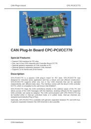
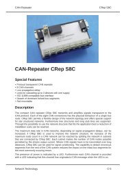
<strong>CPC</strong>-<strong>PCI</strong>/<strong>CC770</strong><strong>User</strong> <strong>Manual</strong>1 Overview1.1 Attributes• CAN Interfaces for industrial applications• Compact size for <strong>PCI</strong> slots• CiA DS 102 and ISO 11898 <strong>com</strong>patible physical layer• Equipped with one or two CAN controller Bosch <strong>CC770</strong>• CAN controller <strong>CC770</strong> <strong>com</strong>patibel to Intel AN82527 CAN controller• Galvanic decoupling between PC and CAN bus (optional)• Easy programming based on direct mapping of CAN controllerregisters into PC memory area1.2 General Description<strong>CPC</strong>-<strong>PCI</strong>/<strong>CC770</strong> is a <strong>PCI</strong> plug-in card for the CAN bus. Designed forindustrial series applications <strong>CPC</strong>-<strong>PCI</strong>/<strong>CC770</strong> has a robust and costefficient layout. <strong>CPC</strong>-<strong>PCI</strong>/<strong>CC770</strong> supports one or two Full-CANcontroller of type Bosch <strong>CC770</strong>.<strong>CPC</strong>-<strong>PCI</strong>/<strong>CC770</strong> maps the CAN controller into the PC addressspace and thus allows access to CAN messages with low latency.Existing software for the supported CAN controller or the <strong>com</strong>patibleIntel type CAN controller AN82527 can easily be adapted. With <strong>CPC</strong>-<strong>PCI</strong>/<strong>CC770</strong> the CAN <strong>com</strong>munication may be handled either ininterrupt controlled or in polled mode.<strong>CPC</strong>-<strong>PCI</strong>/<strong>CC770</strong> can optionally be delivered with galvanicdecoupling of the CAN bus. The dual channel version has theadditional option of galvanic decoupling between the two CANchannels.EMS Dr. Thomas Wünsche5
<strong>User</strong> <strong>Manual</strong><strong>CPC</strong>-<strong>PCI</strong>/<strong>CC770</strong>1.3 Ordering Information10-05-300-20 <strong>CPC</strong>-<strong>PCI</strong>/<strong>CC770</strong>SCAN plug-in board with one CAN controllerBosch <strong>CC770</strong>10-05-301-20 <strong>CPC</strong>-<strong>PCI</strong>/<strong>CC770</strong>S-GTICAN plug-in board with one CAN controllerBosch <strong>CC770</strong>, galvanic decoupling10-05-310-20 <strong>CPC</strong>-<strong>PCI</strong>/<strong>CC770</strong>DCAN plug-in board with two CAN controllersBosch <strong>CC770</strong>10-05-311-20 <strong>CPC</strong>-<strong>PCI</strong>/<strong>CC770</strong>D-GTICAN plug-in board with two CAN controllersBosch <strong>CC770</strong>, galvanic decoupling10-05-312-20 <strong>CPC</strong>-<strong>PCI</strong>/<strong>CC770</strong>D-GTISCAN plug-in board with two CAN controllerBosch <strong>CC770</strong>, individual galvanic decoupling10-05-330-20 <strong>CPC</strong>-<strong>PCI</strong>/<strong>CC770</strong>QCAN plug-in board with four CAN controllerBosch <strong>CC770</strong>10-05-331-20 <strong>CPC</strong>-<strong>PCI</strong>/<strong>CC770</strong>Q-GTICAN plug-in board with four CAN controllerBosch <strong>CC770</strong>, galvanic decoupling10-05-332-20 <strong>CPC</strong>-<strong>PCI</strong>/<strong>CC770</strong>Q-GTISCAN plug-in board with four CAN controllerBosch <strong>CC770</strong>, individual galvanic decoupling6 EMS Dr. Thomas Wünsche
<strong>CPC</strong>-<strong>PCI</strong>/<strong>CC770</strong><strong>User</strong> <strong>Manual</strong>2 Programming Interface<strong>CPC</strong>-<strong>PCI</strong>/<strong>CC770</strong> is mapped into the PC memory space with a baseaddress assigned by the PC BIOS. The availability of the CANcontroller(s) int the memory area makes the CAN <strong>com</strong>municationdirect and provides a low latency time. The card is identified by thefollowing parameters:Vendor IDDevice IDSubvendor IDSubsystem ID: 0x10B5: 0x9030: 0x10B5: 0x4001<strong>CPC</strong>-<strong>PCI</strong>/<strong>CC770</strong> incorporates a PLX9030 <strong>PCI</strong> to local bus bridge.BAR0 of the <strong>PCI</strong> configuration space register points to the bridgeregisters, whereas BAR2 plus an offset of 0x400 points to the first<strong>CC770</strong> CAN controller. BAR2 plus an offset of 0x600 points to theoptional second <strong>CC770</strong> CAN controller.Please contact EMS Dr. Thomas Wünsche for more detailedinformation about the programming interface of <strong>CPC</strong>-<strong>PCI</strong>.EMS Dr. Thomas Wünsche7
<strong>User</strong> <strong>Manual</strong><strong>CPC</strong>-<strong>PCI</strong>/<strong>CC770</strong>THIS PAGE INTENTIONALLY LEFT BLANK8 EMS Dr. Thomas Wünsche
<strong>CPC</strong>-<strong>PCI</strong>/<strong>CC770</strong><strong>User</strong> <strong>Manual</strong>3 Electrical Characteristics3.1 Absolute Limiting ValuesAny (also temporary) stress in excess of the limiting values maycause permanent damage on <strong>CPC</strong>-<strong>PCI</strong>/<strong>CC770</strong> and connecteddevices.Parameter Min. Max. UnitStorage temperature -20 80 °COperating temperature* 0 60 °CVoltage on the bus connections -30 30 VCurrent across ground connection- 1 A* Extended temperature range on demand3.2 Nominal ValuesParameter Min. Typ. Max. UnitPower supply on +5V Pins ofthe <strong>PCI</strong> expansion slot4.75 5 5.25 VVoltage on bus pins* -30 - 30 VCAN controller clock frequency - 16 - MHz* This potential is measured against the ground potential of the related CANtransceiverEMS Dr. Thomas Wünsche9
<strong>User</strong> <strong>Manual</strong><strong>CPC</strong>-<strong>PCI</strong>/<strong>CC770</strong>THIS PAGE INTENTIONALLY LEFT BLANK10 EMS Dr. Thomas Wünsche
<strong>CPC</strong>-<strong>PCI</strong>/<strong>CC770</strong><strong>User</strong> <strong>Manual</strong>4 Operating Instructions4.1 Pin configuration of CAN connectorThe CAN interface connector (D-Sub 9 male) schema <strong>com</strong>plies toCiA Standard DS 102. The pin usage is detailed in the followingtable:Pin Name Description1 - Reserved by CiA, not connected2 CAN_L CAN low bus line3 GND CAN Ground4 - Reserved by CiA, not connected5 - Reserved by CiA, not connected6 - Reserved by CiA, not connected7 CAN_H CAN high bus line8 - Reserved by CiA, not connected9 - Reserved by CiA, not connected4.2 Configuration<strong>CPC</strong>-<strong>PCI</strong>/<strong>CC770</strong> is a Plug and Play interface and therefore does notneed a configuration. The base address of the interface within thePC memory and the interrupt used is assigned by the PC BIOS.EMS Dr. Thomas Wünsche11
<strong>User</strong> <strong>Manual</strong><strong>CPC</strong>-<strong>PCI</strong>/<strong>CC770</strong>4.3 Installation<strong>CPC</strong>-<strong>PCI</strong>/<strong>CC770</strong> may be installed in an empty expansion slot on themotherboard of your IBM <strong>com</strong>patible <strong>com</strong>puter. To avoid damageplease pay attention to the following hints:WARNING: Computer devices and <strong>com</strong>ponents are sensitiveagainst static discharge. For this reason keep <strong>CPC</strong>-<strong>PCI</strong>/<strong>CC770</strong> inthe antistatic cover until installing. Just before removing <strong>CPC</strong>-<strong>PCI</strong>/<strong>CC770</strong> from the protection cover touch the metal case of your<strong>com</strong>puter.Avoid damage by achieving equal potential between all devices onthe CAN before plugging the connection.To the rear side connector of <strong>CPC</strong>-<strong>PCI</strong>/<strong>CC770</strong> only CAN networkswith a connector and elecrical character <strong>com</strong>plying with CiA DS-102may be attached.PC interface and CAN bus are not galvanic decoupled in thestandard version of <strong>CPC</strong>-<strong>PCI</strong>/<strong>CC770</strong>. Use in systems with divergingground potential of PC and CAN bus is not permitted in this case.Besides the instructions mentioned in this manual carefully observethe instructions in your <strong>com</strong>puters user manual.If you are not sure about the installation please contact EMS Dr.Thomas Wünsche.12 EMS Dr. Thomas Wünsche
<strong>User</strong> <strong>Manual</strong><strong>CPC</strong>-<strong>PCI</strong>/<strong>CC770</strong>THIS PAGE INTENTIONALLY LEFT BLANK14 EMS Dr. Thomas Wünsche