8714i Calibration Verification - Rosemount
8714i Calibration Verification - Rosemount
8714i Calibration Verification - Rosemount

You also want an ePaper? Increase the reach of your titles
YUMPU automatically turns print PDFs into web optimized ePapers that Google loves.
White paper: Understanding the <strong>8714i</strong> <strong>Calibration</strong> <strong>Verification</strong> Diagnostic<br />
January 2008 – Page 2<br />
®<br />
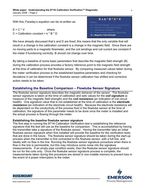
With this, Faraday’s equation can be re-written as:<br />
E = C * V<br />
where<br />
C = <strong>Calibration</strong> constant = k * B * D<br />
We have already discussed that k and D are fixed; this means that the only variable that will<br />
result in a change in the calibration constant is a change in the magnetic field. Since there are<br />
no moving parts to a magnetic flowmeter, and the coil windings and coil current are constant if<br />
the meter if functioning correctly, B should not change over time.<br />
By taking a baseline of some basic parameters that describe the magnetic field strength (B)<br />
during the calibration process provides a factory reference point to the magnetic field strength<br />
at the time of calibration for that flowtube sensor. By comparing measured values taken during<br />
the meter verification process to the established baseline parameters and checking for<br />
deviations it can be determined if the flowtube sensor calibration has shifted and corrective<br />
action needs to be taken.<br />
Establishing the Baseline Comparison – Flowtube Sensor Signature<br />
The flowtube sensor signature describes the magnetic behavior of the sensor. The flowtube<br />
sensor signature is taken at the time of calibration and sets values for the coil signature (a<br />
measure of the magnetic field strength) and the coil resistance (an indication of coil circuit<br />
health). One signature value that is not established at the time of calibration is the electrode<br />
resistance (an indication of the electrode circuit health). Because the electrode resistance will<br />
be dependant on the conductivity of the process fluid in the flowtube sensor at the time of<br />
calibration, the signature of this parameter needs to be done once the meter is installed and<br />
the actual process is flowing through the meter.<br />
Establishing the baseline flowtube sensor signature<br />
The first step in running the <strong>8714i</strong> <strong>Calibration</strong> <strong>Verification</strong> test is establishing the reference<br />
signature that the test will use as the baseline for comparison. This is accomplished by having<br />
the transmitter take a signature of the flowtube sensor. Having the transmitter take an initial<br />
flowtube sensor signature when first installed will provide the baseline for the verification tests<br />
that are done in the future. The flowtube sensor signature should be taken during the start-up<br />
process when the transmitter is first connected to the flowtube sensor, with a full line, and<br />
ideally with no flow in the line. Running the flowtube sensor signature procedure when there is<br />
flow in the line is permissible, but this may introduce some noise into the signature<br />
measurements. If an empty pipe condition exists, then the flowtube sensor signature should<br />
be run for the coils only. Once the flowtube sensor signature process is complete, the<br />
measurements taken during this procedure are stored in non-volatile memory to prevent loss in<br />
the event of a power interruption to the meter.<br />
www.rosemount.com