8714i Calibration Verification - Rosemount
8714i Calibration Verification - Rosemount
8714i Calibration Verification - Rosemount

You also want an ePaper? Increase the reach of your titles
YUMPU automatically turns print PDFs into web optimized ePapers that Google loves.
White paper: Understanding the <strong>8714i</strong> <strong>Calibration</strong> <strong>Verification</strong> Diagnostic<br />
January 2008 – Page 1<br />
®<br />
<strong>8714i</strong> <strong>Calibration</strong> <strong>Verification</strong><br />
The <strong>8714i</strong> <strong>Calibration</strong> <strong>Verification</strong> diagnostic provides a means of verifying the flowmeter is<br />
within calibration without requiring a process shutdown or removal of the flowtube sensor. This<br />
is a manually initiated diagnostic test that provides a review of the transmitter and flowtube<br />
sensors critical parameters as a means to document verification of calibration. The results of<br />
running this diagnostic provide the deviation amount from expected values and a pass/fail<br />
summary against user-defined criteria for the application and conditions.<br />
The <strong>8714i</strong> <strong>Calibration</strong> <strong>Verification</strong> diagnostic can be initiated as required by the application. If<br />
the advanced diagnostic suite (DA2) was ordered, then the <strong>8714i</strong> <strong>Calibration</strong> <strong>Verification</strong><br />
diagnostic will be available. If DA2 was not ordered or licensed, this diagnostic will not be<br />
available.<br />
Meter <strong>Verification</strong> Theory of Operation<br />
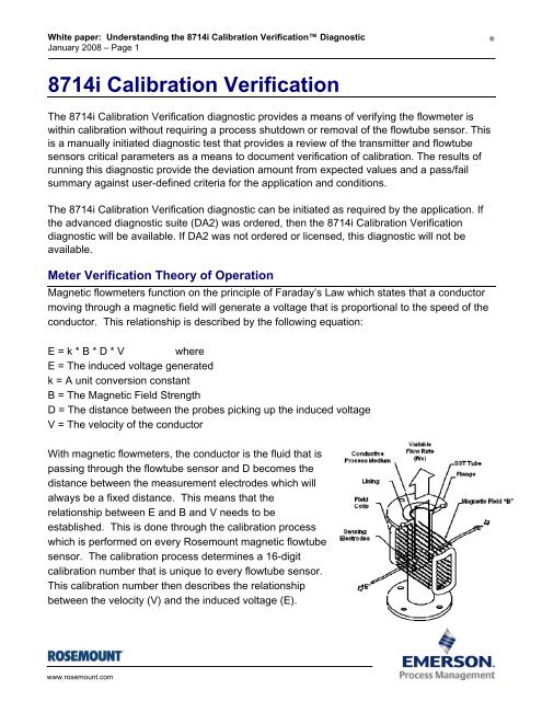
Magnetic flowmeters function on the principle of Faraday’s Law which states that a conductor<br />
moving through a magnetic field will generate a voltage that is proportional to the speed of the<br />
conductor. This relationship is described by the following equation:<br />
E = k * B * D * V where<br />
E = The induced voltage generated<br />
k = A unit conversion constant<br />
B = The Magnetic Field Strength<br />
D = The distance between the probes picking up the induced voltage<br />
V = The velocity of the conductor<br />
With magnetic flowmeters, the conductor is the fluid that is<br />
passing through the flowtube sensor and D becomes the<br />
distance between the measurement electrodes which will<br />
always be a fixed distance. This means that the<br />
relationship between E and B and V needs to be<br />
established. This is done through the calibration process<br />
which is performed on every <strong>Rosemount</strong> magnetic flowtube<br />
sensor. The calibration process determines a 16-digit<br />
calibration number that is unique to every flowtube sensor.<br />
This calibration number then describes the relationship<br />
between the velocity (V) and the induced voltage (E).<br />
www.rosemount.com
White paper: Understanding the <strong>8714i</strong> <strong>Calibration</strong> <strong>Verification</strong> Diagnostic<br />
January 2008 – Page 2<br />
®<br />
With this, Faraday’s equation can be re-written as:<br />
E = C * V<br />
where<br />
C = <strong>Calibration</strong> constant = k * B * D<br />
We have already discussed that k and D are fixed; this means that the only variable that will<br />
result in a change in the calibration constant is a change in the magnetic field. Since there are<br />
no moving parts to a magnetic flowmeter, and the coil windings and coil current are constant if<br />
the meter if functioning correctly, B should not change over time.<br />
By taking a baseline of some basic parameters that describe the magnetic field strength (B)<br />
during the calibration process provides a factory reference point to the magnetic field strength<br />
at the time of calibration for that flowtube sensor. By comparing measured values taken during<br />
the meter verification process to the established baseline parameters and checking for<br />
deviations it can be determined if the flowtube sensor calibration has shifted and corrective<br />
action needs to be taken.<br />
Establishing the Baseline Comparison – Flowtube Sensor Signature<br />
The flowtube sensor signature describes the magnetic behavior of the sensor. The flowtube<br />
sensor signature is taken at the time of calibration and sets values for the coil signature (a<br />
measure of the magnetic field strength) and the coil resistance (an indication of coil circuit<br />
health). One signature value that is not established at the time of calibration is the electrode<br />
resistance (an indication of the electrode circuit health). Because the electrode resistance will<br />
be dependant on the conductivity of the process fluid in the flowtube sensor at the time of<br />
calibration, the signature of this parameter needs to be done once the meter is installed and<br />
the actual process is flowing through the meter.<br />
Establishing the baseline flowtube sensor signature<br />
The first step in running the <strong>8714i</strong> <strong>Calibration</strong> <strong>Verification</strong> test is establishing the reference<br />
signature that the test will use as the baseline for comparison. This is accomplished by having<br />
the transmitter take a signature of the flowtube sensor. Having the transmitter take an initial<br />
flowtube sensor signature when first installed will provide the baseline for the verification tests<br />
that are done in the future. The flowtube sensor signature should be taken during the start-up<br />
process when the transmitter is first connected to the flowtube sensor, with a full line, and<br />
ideally with no flow in the line. Running the flowtube sensor signature procedure when there is<br />
flow in the line is permissible, but this may introduce some noise into the signature<br />
measurements. If an empty pipe condition exists, then the flowtube sensor signature should<br />
be run for the coils only. Once the flowtube sensor signature process is complete, the<br />
measurements taken during this procedure are stored in non-volatile memory to prevent loss in<br />
the event of a power interruption to the meter.<br />
www.rosemount.com
White paper: Understanding the <strong>8714i</strong> <strong>Calibration</strong> <strong>Verification</strong> Diagnostic<br />
January 2008 – Page 3<br />
®<br />
Integrally mounted transmitters will come with the flowtube sensor signature already loaded<br />
into the non-volatile memory. For integrally mounted transmitters this is a standard part of the<br />
calibration procedure. Once the flowtube sensor is installed and the line is filled with process<br />
fluid, the user should perform an electrode circuit signature. The electrode circuit signature is<br />
not taken at the time of calibration due to the wide variety of process fluids used with magnetic<br />
flowmeters.<br />
Transmitters that have been paired to a specific flowtube sensor will also come with the<br />
flowtube sensor signature preloaded into the non-volatile memory.<br />
Transmitters that have not been paired to a specific flowtube sensor, or transmitters ordered<br />
as a replacement will need to have the flowtube sensor signature established once they are<br />
installed in the field.<br />
Understanding the Re-Signature Parameters<br />
When performing a re-signature of the flowtube sensor, there are three signature options<br />
available. Note that when a re-signature is done, it overwrites the existing signature values<br />
stored in the non-volatile memory.<br />
All<br />
Re-signature all values for the flowtube sensor. This includes the coil signature, coil<br />
resistance, and electrode resistance.<br />
Coils<br />
Re-signature the coil values only. This includes the coil signature and the coil<br />
resistance. The electrode resistance is not measured.<br />
Electrodes<br />
Re-signature the electrode resistance value only. The coil signature and coil resistance<br />
are not measured. A re-signature of the electrodes only should be done for new<br />
installations once the flowtube sensor is installed and the pipe is filled with the process<br />
fluid.<br />
Understanding the <strong>8714i</strong> Test Parameters<br />
The <strong>8714i</strong> has a multitude of parameters that set the test criteria, test conditions, and scope of<br />
the calibration verification test.<br />
Test Conditions for the <strong>8714i</strong> <strong>Calibration</strong> <strong>Verification</strong><br />
There are three possible test conditions that the <strong>8714i</strong> <strong>Calibration</strong> <strong>Verification</strong> test can be<br />
initiated under. This parameter is set at the time that the <strong>8714i</strong> <strong>Calibration</strong> <strong>Verification</strong> test is<br />
initiated.<br />
www.rosemount.com
White paper: Understanding the <strong>8714i</strong> <strong>Calibration</strong> <strong>Verification</strong> Diagnostic<br />
January 2008 – Page 4<br />
®<br />
No Flow<br />
Run the <strong>8714i</strong> <strong>Calibration</strong> <strong>Verification</strong> test with a full pipe and no flow in the line.<br />
Running the <strong>8714i</strong> <strong>Calibration</strong> <strong>Verification</strong> test under this condition provides the most<br />
accurate results and the best indication of magnetic flowmeter health. Under this<br />
condition the <strong>8714i</strong> tests against the criteria limits entered for Full Pipe, No Flow.<br />
Flowing, Full<br />
Run the <strong>8714i</strong> <strong>Calibration</strong> <strong>Verification</strong> test with a full pipe and flow in the line. Running<br />
the <strong>8714i</strong> <strong>Calibration</strong> <strong>Verification</strong> test under this condition provides the ability to verify<br />
the magnetic flowmeter health without shutting down the process flow in applications<br />
where a shutdown is not possible. Running the calibration verification under flowing<br />
conditions can cause false fails of the transmitter verification test if the flow rate is not at<br />
a steady flow, or if there is process noise present. Under this condition the <strong>8714i</strong> tests<br />
against the criteria limits entered for Full Pipe, Flowing.<br />
Empty Pipe<br />
Run the <strong>8714i</strong> <strong>Calibration</strong> <strong>Verification</strong> test with an empty pipe. Running the <strong>8714i</strong><br />
<strong>Calibration</strong> <strong>Verification</strong> test under this condition provides the ability to verify the<br />
magnetic flowmeter health with an empty pipe. Running the calibration verification<br />
under empty pipe conditions will not check the electrode circuit health and may result in<br />
false fails of the transmitter verification test as empty pipe conditions generate<br />
significant background noise during the transmitter verification test. Under this condition<br />
the <strong>8714i</strong> tests against the criteria limits entered for Empty Pipe.<br />
<strong>8714i</strong> <strong>Calibration</strong> <strong>Verification</strong> Test Criteria<br />
The <strong>8714i</strong> <strong>Calibration</strong> <strong>Verification</strong> diagnostic provides the ability for the user to define the<br />
maximum allowable deviation for the transmitter calibration and flowtube sensor calibration<br />
verification tests. Deviations results that exceed the established test criteria will cause the test<br />
to fail. The test criteria can be set for each of the flow conditions discussed above.<br />
Full Pipe, No Flow<br />
Set the test criteria for the No Flow condition. The factory default for this value is set to<br />
two percent with limits configurable between one and ten percent.<br />
Full Pipe, Flowing<br />
Set the test criteria for the Flowing, Full condition. The factory default for this value is<br />
set to three percent with limits configurable between one and ten percent.<br />
Empty Pipe<br />
Set the test criteria for the Empty Pipe condition. The factory default for this value is set<br />
to five percent with limits configurable between one and ten percent.<br />
www.rosemount.com
White paper: Understanding the <strong>8714i</strong> <strong>Calibration</strong> <strong>Verification</strong> Diagnostic<br />
January 2008 – Page 5<br />
®<br />
<strong>8714i</strong> <strong>Calibration</strong> <strong>Verification</strong> Test Scope<br />
The <strong>8714i</strong> <strong>Calibration</strong> <strong>Verification</strong> can be used to verify the entire<br />
flowmeter installation, or individual parts such as the transmitter or<br />
flowtube sensor. This parameter is set at the time that the <strong>8714i</strong><br />
<strong>Calibration</strong> <strong>Verification</strong> test is initiated.<br />
All<br />
Run the <strong>8714i</strong> <strong>Calibration</strong> <strong>Verification</strong> test and verify the entire flowmeter installation.<br />
This parameter results in the calibration verification performing the transmitter<br />
calibration verification, tube calibration verification, coil health check, and electrode<br />
health check. Transmitter calibration and tube calibration are verified against the<br />
percentage associated with the test condition selected when the test was initiated.<br />
Transmitter<br />
Run the <strong>8714i</strong> <strong>Calibration</strong> <strong>Verification</strong> test on the transmitter only. This results in the<br />
verification test only checking the transmitter calibration against the limits of the test<br />
criteria selected when the <strong>8714i</strong> <strong>Calibration</strong> <strong>Verification</strong> test was initiated.<br />
Flowtube Sensor<br />
Run the <strong>8714i</strong> <strong>Calibration</strong> <strong>Verification</strong> test on the flowtube sensor only. This causes the<br />
verification test to check the flowtube sensor calibration against the limits of the test<br />
criteria selected when the <strong>8714i</strong> <strong>Calibration</strong> <strong>Verification</strong> test was initiated. This test will<br />
also verify the coil circuit health, and the electrode circuit health.<br />
Test Condition<br />
No Flow,<br />
Full<br />
Flowing,<br />
Full<br />
Empty<br />
Pipe<br />
Test Scope<br />
All Transmitter Flowtube Sensor<br />
Flowtube Sensor Cal Test<br />
Coil Circuit Test<br />
Electrode Circuit Test<br />
Transmitter Cal Test<br />
Flowtube Sensor Cal Test<br />
Coil Circuit Test<br />
Electrode Circuit Test<br />
Transmitter Cal Test<br />
Flowtube Sensor Cal Test<br />
Coil Circuit Test<br />
Transmitter Cal Test<br />
Transmitter Cal Test<br />
Transmitter Cal Test<br />
Transmitter Cal Test<br />
Flowtube Sensor Cal<br />
Test<br />
Coil Circuit Test<br />
Electrode Circuit Test<br />
Flowtube Sensor Cal<br />
Test<br />
Coil Circuit Test<br />
Electrode Circuit Test<br />
Flowtube Sensor Cal<br />
Test<br />
Coil Circuit Test<br />
www.rosemount.com
White paper: Understanding the <strong>8714i</strong> <strong>Calibration</strong> <strong>Verification</strong> Diagnostic<br />
January 2008 – Page 6<br />
®<br />
Understanding the <strong>8714i</strong> Test Results<br />
Once the <strong>8714i</strong> <strong>Calibration</strong> <strong>Verification</strong> test is initiated, the transmitter will make several<br />
measurements to verify the transmitter calibration, tube calibration, coil circuit health, and<br />
electrode circuit health. The results of these tests can be reviewed and recorded on the<br />
<strong>Rosemount</strong> Magnetic Flowmeter <strong>Calibration</strong> Report (00816-0200-4727). This report can be<br />
used to validate that the meter is within the required calibration limits to comply with<br />
governmental regulatory agencies such as the Environmental Protection Agency or Food and<br />
Drug Administration.<br />
Viewing the <strong>8714i</strong> <strong>Calibration</strong> <strong>Verification</strong> Results<br />
Depending on the method used to view the results, they will be displayed in either a menu<br />
structure, as a method, or in the report format. When using the HART Field Communicator,<br />
each individual component can be viewed as a menu item. When using the LOI, the<br />
parameters are viewed as a method using the left arrow key to cycle through the results. In<br />
AMS the calibration report is populated with the necessary data eliminating the need to<br />
manually complete the report found on page xx.<br />
NOTE<br />
When using AMS there are two possible methods that can be used to print the verification report.<br />
Method one involves taking a PrntScrn picture of the <strong>8714i</strong> Report tab on the status screen and pasting it into a<br />
word processing program. The PrntScrn button will capture all items on the screen so the image will need to be<br />
cropped and resized in order to get only the report.<br />
Method two involves using the print feature within AMS while on the status screen. This will result in a printout of<br />
all of the information stored on the status tabs. Page two of the report will contain all of the necessary calibration<br />
verification result data.<br />
The verification results are displayed in the following order on the LOI:<br />
Test Condition<br />
Displays the test condition under which the <strong>8714i</strong> was performed.<br />
Test Criteria<br />
Displays the maximum allowable deviation percentage before a verification test will fail.<br />
<strong>8714i</strong> Result<br />
Displays the overall result of the <strong>8714i</strong> <strong>Calibration</strong> <strong>Verification</strong> test as either a Pass or<br />
Fail.<br />
www.rosemount.com
White paper: Understanding the <strong>8714i</strong> <strong>Calibration</strong> <strong>Verification</strong> Diagnostic<br />
January 2008 – Page 7<br />
®<br />
Simulated Velocity<br />
Displays the simulated velocity used to verify the transmitter calibration.<br />
Actual Velocity<br />
Displays the velocity measured by the transmitter during the calibration verification<br />
process.<br />
Velocity Deviation<br />
Displays the deviation in the Actual Velocity compared to the Simulated Velocity in<br />
terms of a percentage. This percentage is then compared to the test criteria to<br />
determine if the transmitter is within calibration limits.<br />
Transmitter <strong>Calibration</strong> <strong>Verification</strong><br />
Displays the results of the transmitter calibration verification test as either a Pass or<br />
Fail.<br />
Flowtube Sensor <strong>Calibration</strong> Deviation<br />
Displays the deviation in the measured coil signature to the baseline coil signature to<br />
determine if the flowtube sensor calibration has shifted. This percentage is compared to<br />
the test criteria to determine if the flowtube sensor is within calibration limits.<br />
Flowtube Sensor <strong>Calibration</strong> <strong>Verification</strong><br />
Displays the results of the flowtube sensor calibration verification test as either a Pass<br />
or Fail.<br />
Coil Circuit <strong>Verification</strong><br />
Displays the results of the coil circuit health check as either a Pass or Fail.<br />
Electrode Circuit <strong>Verification</strong><br />
Displays the results of the electrode circuit health check as either a Pass or Fail.<br />
www.rosemount.com
White paper: Understanding the <strong>8714i</strong> <strong>Calibration</strong> <strong>Verification</strong> Diagnostic<br />
January 2008 – Page 8<br />
®<br />
Meter <strong>Verification</strong> Report Examples<br />
Once the meter verification diagnostic has completed, it is possible to print a verification report<br />
for submission to a regulatory agency or file with the instrument file. If using AMS, the report is<br />
populated automatically with the appropriate information. If using a 375 or the LOI, a report is<br />
available to fill out manually.<br />
Optimizing the <strong>8714i</strong> <strong>Calibration</strong> <strong>Verification</strong><br />
The <strong>8714i</strong> <strong>Calibration</strong> <strong>Verification</strong> diagnostic can be optimized by setting the test criteria to the<br />
desired levels necessary to meet the compliance requirements of the application. The<br />
following examples below will provide some guidance on how to set these levels.<br />
Example<br />
An effluent meter must be certified every year to comply with Environmental Protection<br />
Agency and Pollution Control Agency standards. These governmental agencies require<br />
that the meter be certified to five percent accuracy.<br />
Since this is an effluent meter, shutting down the process may not be viable. In this<br />
instance the <strong>8714i</strong> <strong>Calibration</strong> <strong>Verification</strong> test will be performed under flowing<br />
conditions. Set the test criteria for Flowing, Full to five percent to meet the requirements<br />
of the governmental agencies.<br />
Example<br />
A pharmaceutical company requires bi-annual verification of meter calibration on a<br />
critical feed line for one of their products. This is an internal standard, but plant<br />
requirements require a calibration record be kept on-hand. Meter calibration on this<br />
process must meet one percent. The process is a batch process so it is possible to<br />
perform the calibration verification with the line full and with no flow. Since the <strong>8714i</strong><br />
www.rosemount.com
White paper: Understanding the <strong>8714i</strong> <strong>Calibration</strong> <strong>Verification</strong> Diagnostic<br />
January 2008 – Page 9<br />
®<br />
<strong>Calibration</strong> <strong>Verification</strong> test can be run under no flow conditions, set the test criteria for<br />
No Flow to one percent to comply with the necessary plant standards.<br />
Example<br />
A food and beverage company requires an annual calibration of a meter on a product<br />
line. The plant standard calls for the accuracy to be three percent or better. They<br />
manufacture this product in batches, and the measurement cannot be interrupted when<br />
a batch is in process. When the batch is complete, the line goes empty. Since there is<br />
no means of performing the <strong>8714i</strong> <strong>Calibration</strong> <strong>Verification</strong> test while there is product in<br />
the line, the test must be performed under empty pipe conditions. The test criteria for<br />
Empty Pipe should be set to three percent, and it should be noted that the electrode<br />
circuit health cannot be verified.<br />
Once the test criteria is established and the flowtube sensor signature values taken, it is<br />
suggested to run the <strong>8714i</strong> <strong>Calibration</strong> <strong>Verification</strong> test to verify that the verification test can<br />
provide the desired results. This also serves to provide a baseline as it provides an initial<br />
“good” test point to compare to in the event that the verification fails in a future test.<br />
www.rosemount.com
White paper: Understanding the <strong>8714i</strong> <strong>Calibration</strong> <strong>Verification</strong> Diagnostic<br />
January 2008 – Page 10<br />
®<br />
Troubleshooting the <strong>8714i</strong> <strong>Calibration</strong> <strong>Verification</strong> Test<br />
In the event that the <strong>8714i</strong> <strong>Calibration</strong> <strong>Verification</strong> test fails, the following steps can be used to<br />
determine the appropriate course of action. Begin by reviewing the <strong>8714i</strong> results to determine<br />
the specific test that failed.<br />
Test Potential Cause of Failure Steps to Correct<br />
Transmitter <strong>Calibration</strong><br />
<strong>Verification</strong> Test Failed<br />
• Unstable flow rate during<br />
the verification test<br />
• Noise in the process<br />
• Transmitter drift<br />
• Faulty electronics<br />
• Perform the test with no<br />
flow in the pipe<br />
• Check calibration with an<br />
external standard like the<br />
8714D<br />
• Perform a digital trim<br />
• Replace the electronics<br />
Flowtube Sensor<br />
<strong>Calibration</strong> <strong>Verification</strong><br />
Failed<br />
Coil Circuit Health<br />
Failed<br />
Electrode Circuit<br />
Health Failed<br />
• Moisture in the terminal<br />
block of the flowtube<br />
sensor<br />
• <strong>Calibration</strong> shift caused by<br />
heat cycling or vibration<br />
• Moisture in the terminal<br />
block of the flowtube<br />
sensor<br />
• Shorted Coil<br />
• Electrode Signature was<br />
never performed<br />
• Moisture in the terminal<br />
block of the flowtube<br />
sensor<br />
• Coated Electrodes<br />
• Shorted Electrodes<br />
• Remove the flowtube<br />
sensor and send back for<br />
recalibration.<br />
• Perform the flowtube<br />
sensor checks detailed in<br />
the manual.<br />
• Perform the electrode<br />
signature and re-run the<br />
verification test<br />
• Perform the flowtube<br />
sensor checks detailed in<br />
the manual.<br />
www.rosemount.com
White paper: Understanding the <strong>8714i</strong> <strong>Calibration</strong> <strong>Verification</strong> Diagnostic<br />
January 2008 – Page 11<br />
®<br />
<strong>8714i</strong> <strong>Calibration</strong> <strong>Verification</strong> Functionality<br />
The <strong>8714i</strong> <strong>Calibration</strong> <strong>Verification</strong> diagnostic functions by taking a baseline flowtube sensor<br />
signature and then comparing measurements taken during the verification test to these<br />
baseline results.<br />
Flowtube Signature Values<br />
The flowtube sensor signature describes the magnetic behavior of the sensor. Based<br />
on Faraday’s law, the induced voltage measured on the electrodes is proportional to the<br />
magnetic field strength. Thus, any changes in the magnetic field will result in a<br />
calibration shift of the flowtube sensor. Having the transmitter take an initial flowtube<br />
sensor signature when first installed will provide the baseline for the verification tests<br />
that are done in the future. There are three specific measurements that are stored in<br />
the transmitter’s non-volatile memory that are used when performing the calibration<br />
verification.<br />
Coil Circuit Resistance<br />
The Coil Circuit Resistance is a measurement of the coil circuit health. This value is<br />
used as a baseline to determine if the coil circuit is still operating correctly when the<br />
<strong>8714i</strong> <strong>Calibration</strong> <strong>Verification</strong> diagnostic is initiated.<br />
Coil Signature<br />
The Coil Signature is a measurement of the magnetic field strength. This value is used<br />
as a baseline to determine if a flowtube sensor calibration shift has occurred when the<br />
<strong>8714i</strong> <strong>Calibration</strong> <strong>Verification</strong> diagnostic is initiated.<br />
Electrode Circuit Resistance<br />
The Electrode Circuit Resistance is a measurement of the electrode circuit health. This<br />
value is used as a baseline to determine if the electrode circuit is still operating correctly<br />
when the <strong>8714i</strong> <strong>Calibration</strong> <strong>Verification</strong> diagnostic is initiated.<br />
<strong>8714i</strong> <strong>Calibration</strong> <strong>Verification</strong> Measurements<br />
The <strong>8714i</strong> <strong>Calibration</strong> <strong>Verification</strong> test will make measurements of the coil resistance,<br />
coil signature, and electrode resistance and compare these values to the values taken<br />
during the flowtube sensor signature process to determine the flowtube sensor<br />
calibration deviation, the coil circuit health, and the electrode circuit health. In addition,<br />
the measurements taken by this test can provide additional information when<br />
troubleshooting the meter.<br />
Coil Circuit Resistance<br />
The Coil Circuit Resistance is a measurement of the coil circuit health. This value is<br />
compared to the coil circuit resistance baseline measurement taken during the flowtube<br />
signature process to determine coil circuit health.<br />
www.rosemount.com
White paper: Understanding the <strong>8714i</strong> <strong>Calibration</strong> <strong>Verification</strong> Diagnostic<br />
January 2008 – Page 12<br />
®<br />
Coil Signature<br />
The Coil Signature is a measurement of the magnetic field strength. This value is<br />
compared to the coil signature baseline measurement taken during the flowtube<br />
signature process to determine tube calibration deviation.<br />
Electrode Circuit Resistance<br />
The Electrode Circuit Resistance is a measurement of the electrode circuit health. This<br />
value is compared to the electrode circuit resistance baseline measurement taken<br />
during the flowtube signature process to determine electrode circuit health.<br />
www.rosemount.com
White paper: Understanding the <strong>8714i</strong> <strong>Calibration</strong> <strong>Verification</strong> Diagnostic<br />
January 2008 – Page 13<br />
®<br />
The contents of this publication are presented for informational purposes only, and while effort has been made to ensure their accuracy, they are<br />
not to be construed as warranties or guarantees, express or implied, regarding the products or services described herein or their use or<br />
applicability. All sales are governed by our terms and conditions, which are available on request. We reserve the right to modify or improve the<br />
designs or specifications of our products at any time without notice.<br />
The Emerson logo is a trade mark and service mark of Emerson Electric Co.<br />
<strong>Rosemount</strong> and the <strong>Rosemount</strong> logotype are registered trademarks of <strong>Rosemount</strong> Inc.<br />
All other marks are the property of their respective owners.<br />
Emerson Process Management<br />
<strong>Rosemount</strong> Inc.<br />
8200 Market Boulevard<br />
Chanhassen, MN 55317 USA<br />
T (U.S.) 1-800-999-9307<br />
T (International) (952) 906-8888<br />
F (952) 949-7001<br />
www.rosemount.com<br />
© 2005 Emerson Process Management. All rights reserved.