7851-7851c-7852 field strength meter user manual - Sefram
7851-7851c-7852 field strength meter user manual - Sefram
7851-7851c-7852 field strength meter user manual - Sefram

Create successful ePaper yourself
Turn your PDF publications into a flip-book with our unique Google optimized e-Paper software.
<strong>7851</strong>-<strong>7851</strong>C-<strong>7852</strong><br />
FIELD STRENGTH METER<br />
USER MANUAL<br />
November 2007<br />
M<strong>7851</strong>001A/08
– <strong>7851</strong>-<strong>7851</strong>C-<strong>7852</strong> –<br />
Thank you for purchasing this SEFRAM product and therefore trusting our company. Our different teams<br />
(reseach department, production, sales department, after-sales service,…) are aiming at satisfying your<br />
wishes by designing and updating very advanced appliances.<br />
To obtain the best performance from this product please read this <strong>manual</strong> carefully.<br />
For more information please contact our different services :<br />
Sales department<br />
After-sales service<br />
Technical support<br />
e-mail : sales@sefram.fr<br />
e-mail : sav@sefram.fr<br />
e-mail : support@sefram.fr<br />
Fax : +33 (0)4 77 57 23 23<br />
Website : www.sefram.fr<br />
Copyright <strong>Sefram</strong>, 2007. All rights reserved.<br />
Any total or partial reproduction of this document must be submitted for <strong>Sefram</strong> authorization.<br />
p. 3
– <strong>7851</strong>-<strong>7851</strong>C-<strong>7852</strong> –<br />
GARANTY<br />
Your instrument is guaranteed for two years in parts and work time against any default of manufacture and/or contingencies in<br />
the functioning. This guaranty starts at the date of delivery and ends 730 calendar days later.<br />
If the appliance is subject to a guaranty contract, this contract cancels and replaces the above mentioned conditions of guaranty.<br />
This guaranty does not include any fault of use and/or error of handling.<br />
In case of use of the guaranty, the <strong>user</strong> must send back, with its expenses, the concerned appliance to our factory:<br />
SEFRAM Instruments & Systèmes<br />
Service Après-Vente<br />
32, rue Edouard MARTEL<br />
BP 55<br />
42009 SAINT-ETIENNE CEDEX 2<br />
The accessory items furnished as standard with the appliance (cables, plugs…), consumable items (battery, …) and the optional<br />
accessory items (bag, case…) are guaranteed for 3 months against any default of manufacture.<br />
The factory options in the appliance are guaranteed for the same time as the appliance.<br />
What to do in case of malfunction?<br />
In case of malfunction or for any problem of use, please join the technical assistance by SEFRAM Instruments & Systems.<br />
A technician will take your call in charge and will give you any necessary information to solve your problem.<br />
What to do in case of crash?<br />
In case of crash of the appliance, please join our after-sales service.<br />
Some advice?<br />
Some technical help required?<br />
SEFRAM Instruments & Systems commits itself to help you by phone for the use of your appliance.<br />
Please phone:<br />
(00 33) 825 56 50 50 Technical help for products<br />
or send an e- mail to:<br />
support@sefram.fr<br />
p. 4
– <strong>7851</strong>-<strong>7851</strong>C-<strong>7852</strong> –<br />
1 IMPORTANT INFORMATION ...............................................................................................9<br />
1.1 Precautions ....................................................................................................................................................9<br />
1.2 Safety instructions ..........................................................................................................................................9<br />
1.3 Symbols and definitions .................................................................................................................................9<br />
1.4 Conformity and appliance limits .....................................................................................................................9<br />
2 Quickstart guide.................................................................................................................11<br />
3 Presentation .......................................................................................................................17<br />
3.1 General.........................................................................................................................................................17<br />
3.2 Description ...................................................................................................................................................18<br />
3.2.1 Front panel................................................................................................................................................18<br />
3.2.2 Function keys............................................................................................................................................19<br />
3.2.3 Connectors (upper panel)........................................................................................................................20<br />
3.2.4 Use of the straps.......................................................................................................................................20<br />
3.2.5 Man-machine Interfacing ..........................................................................................................................21<br />
3.2.6 Structure of Places, Setups and Frequency band....................................................................................23<br />
3.2.7 Number of places and Setups ..................................................................................................................24<br />
4 Operating the appliance ....................................................................................................25<br />
4.1 Battery ..........................................................................................................................................................25<br />
4.2 Charging the battery.....................................................................................................................................25<br />
4.3 External power supply..................................................................................................................................26<br />
4.4 Powering up the appliance...........................................................................................................................26<br />
4.5 Connecting the appliance to a PC................................................................................................................26<br />
4.5.1 Necessary configuration ...........................................................................................................................26<br />
4.5.2 Installing the drivers..................................................................................................................................26<br />
4.5.3 Updating the software...............................................................................................................................29<br />
5 AUTOSET Mode..................................................................................................................31<br />
5.1 Terrestrial Mode ...........................................................................................................................................31<br />
5.2 Cable Mode ..................................................................................................................................................32<br />
5.3 Satellite Mode...............................................................................................................................................32<br />
5.4 « Scan » menu key.......................................................................................................................................32<br />
6 Configuration of Places.....................................................................................................33<br />
6.1 Para<strong>meter</strong>s...................................................................................................................................................33<br />
6.2 Setup list.......................................................................................................................................................34<br />
7 Spectrum Analyzer.............................................................................................................35<br />
8 Normal Check satellite and Double LNB..........................................................................37<br />
8.1 <strong>Sefram</strong>Sat software......................................................................................................................................37<br />
8.1.1 Installation.................................................................................................................................................37<br />
8.1.2 How to use <strong>Sefram</strong>Sat..............................................................................................................................38<br />
8.2 Checksat mode interface..............................................................................................................................39<br />
8.3 Normal checksat...........................................................................................................................................40<br />
8.3.1 Normal checksat information ....................................................................................................................40<br />
8.4 Double checksat...........................................................................................................................................41<br />
8.5 Modification of a transponder’s para<strong>meter</strong>s.................................................................................................42<br />
9 Image and Sound ...............................................................................................................43<br />
p. 5
– <strong>7851</strong>-<strong>7851</strong>C-<strong>7852</strong> –<br />
9.1 Analog TV.....................................................................................................................................................43<br />
9.1.1 Volume and screen settings .....................................................................................................................43<br />
9.1.2 Full Screen Mode......................................................................................................................................44<br />
9.1.3 Synchro signal ..........................................................................................................................................45<br />
9.2 MPEG2 TV ...................................................................................................................................................45<br />
9.2.1 Services list...............................................................................................................................................46<br />
9.2.2 Access rights / access card ......................................................................................................................46<br />
10 Level / power measurement ..............................................................................................47<br />
10.1 Para<strong>meter</strong>s...................................................................................................................................................47<br />
10.2 Measurements according to Standard .........................................................................................................48<br />
10.2.1 Terrestrial Band.....................................................................................................................................48<br />
10.2.2 Satellite Band ........................................................................................................................................49<br />
11 Error rate measurement ....................................................................................................51<br />
11.1 Para<strong>meter</strong>s...................................................................................................................................................51<br />
11.2 DVB-C ..........................................................................................................................................................52<br />
11.3 DVB-S, DSS .................................................................................................................................................52<br />
11.4 DVB-S2 ........................................................................................................................................................52<br />
11.5 DVB-T/H (COFDM) ......................................................................................................................................53<br />
11.6 NICAM..........................................................................................................................................................53<br />
12 Impulse response (DVB-T/H only) ....................................................................................55<br />
13 LNB - DISEqC .....................................................................................................................57<br />
13.1 Satellite Band ...............................................................................................................................................57<br />
13.2 Terrestrial band ............................................................................................................................................57<br />
14 Configuration .....................................................................................................................59<br />
14.1 Language, date, time, LCD and beep ..........................................................................................................59<br />
14.2 Measurement unit.........................................................................................................................................59<br />
14.3 Correction coefficients..................................................................................................................................59<br />
14.4 Memories......................................................................................................................................................60<br />
14.4.1 Folders ..................................................................................................................................................60<br />
14.4.2 File list ...................................................................................................................................................60<br />
14.5 Initializations.................................................................................................................................................61<br />
15 Save / Recall .......................................................................................................................63<br />
15.1 Save .............................................................................................................................................................64<br />
15.2 Recall............................................................................................................................................................64<br />
15.3 Save / Recall Measurement Map .................................................................................................................64<br />
15.4 Spectrum curve superposition......................................................................................................................64<br />
16 Measurement map..............................................................................................................67<br />
16.1 Entering / changing a setup number ............................................................................................................67<br />
16.2 Automatic sorting..........................................................................................................................................68<br />
16.3 Out of tolerance values ................................................................................................................................68<br />
16.4 Graphic display.............................................................................................................................................68<br />
17 Messages............................................................................................................................71<br />
17.1 Warning messages.......................................................................................................................................71<br />
p. 6
– <strong>7851</strong>-<strong>7851</strong>C-<strong>7852</strong> –<br />
17.2 Error messages ............................................................................................................................................71<br />
17.3 Failure messages .........................................................................................................................................72<br />
18 Maintenance .......................................................................................................................75<br />
19 Specifications.....................................................................................................................77<br />
19.1 Common technical features 785x.................................................................................................................77<br />
19.2 DVB-C (<strong>7851</strong>C, 7853, 7855, 7856) ..............................................................................................................78<br />
19.3 MCNS (<strong>7851</strong>C, 7853, 7855, 7856)...............................................................................................................78<br />
19.4 DVB-S, DSS (except for 7853)....................................................................................................................78<br />
19.5 DVB-S2 (except for 7853) ............................................................................................................................79<br />
19.6 DVB-T/H (except for 7853)...........................................................................................................................79<br />
19.7 NICAM 728...................................................................................................................................................80<br />
19.8 Image and sound demodulation..................................................................................................................80<br />
19.9 Remote supply .............................................................................................................................................80<br />
19.10 Power supply – battery .............................................................................................................................80<br />
19.11 Environment..............................................................................................................................................81<br />
19.12 Miscellaneous ...........................................................................................................................................81<br />
19.13 Accessories ..............................................................................................................................................81<br />
19.14 V, dBµV, dBmV and dBm conversion.......................................................................................................81<br />
DECLARATION CE...................................................................................................................83<br />
p. 7
– <strong>7851</strong>-<strong>7851</strong>C-<strong>7852</strong> –<br />
p. 8
– <strong>7851</strong>-<strong>7851</strong>C-<strong>7852</strong> –<br />
1 IMPORTANT INFORMATION<br />
1.1 Precautions<br />
Please read carefully the following instructions before using your appliance.<br />
• Do not use your appliance for any other use that it is described in the <strong>manual</strong>.<br />
• Use the charger block provided to avoid any deterioration of the appliance and to protect its<br />
measurement characteristics.<br />
• Do not use in a wet environnement.<br />
• Do not use in an explosive environnement.<br />
• In case of defect or for the maintenance of the appliance, please contact our service depart<br />
ment.<br />
• Do not open the appliance, risk of electric shock.<br />
1.2 Safety instructions<br />
For a correct use of the appliance, you have to respect the safety instructions and directions for use described<br />
in this <strong>manual</strong>.<br />
Specific warnings are provided all along this <strong>user</strong> <strong>manual</strong>.<br />
You can also find caution symbols on the appliance :<br />
1.3 Symbols and definitions<br />
Symbols appearing in this <strong>manual</strong> :<br />
Remark : indicates important information.<br />
Symbols appearing on the appliance :<br />
Caution : see <strong>user</strong> <strong>manual</strong>. Indicates a risk of deterioration for the equipment connected to<br />
the appliance or for the appliance itself.<br />
Ground : accessible parts connected to the appliance’s metallic chassis.<br />
Product to be recycled.<br />
1.4 Conformity and appliance limits<br />
See chapter « Declaration of CE conformity ».<br />
p. 9
– <strong>7851</strong>-<strong>7851</strong>C-<strong>7852</strong> –<br />
p. 10
2 Quickstart guide<br />
– <strong>7851</strong>-<strong>7851</strong>C-<strong>7852</strong> –<br />
Field <strong>strength</strong> <strong>meter</strong> 785X<br />
So much easier to use with the AUTOSET key !<br />
Important keys :<br />
: AUTOSET : SPECTRUM : LNB-DISEqC<br />
: PARAMETERS : LEVEL : TV<br />
I want to work :<br />
In terrestrial mode<br />
In satellite mode<br />
In any case, the AUTOSET key guides you ! ! !<br />
p. 11
– <strong>7851</strong>-<strong>7851</strong>C-<strong>7852</strong> –<br />
AUTOSET :<br />
This mode permits to perform an automatic setup search and to inform the current place.<br />
Caution : Your antenna or your dish must be correctly positioned before you press the AUTOSET<br />
key. (Please see CHECKSATELLITE to see how you can correctly position a dish).<br />
1/ Press the AUTOSET key :<br />
2/ Select mode (terrestrial, satellite or cable) according to your search. The frequencies map (in terrestrial<br />
or cable mode) is already preselected according to your country.<br />
If you need to, you can change the frequencies map by selecting « frequencies map ».<br />
3/ The direction keys (up/down and left/right) permit to move in the para<strong>meter</strong>s table. The central key permit<br />
to confirm / cancel a para<strong>meter</strong>.<br />
Direction keys<br />
Central key<br />
4/ When you have correctly informed the table, press the « Scan » key to launch search.<br />
5/ A warning message indicates that the current place<br />
will be crushed. The current place will be replaced then<br />
by the found setups. Press “Yes” for the following message:<br />
p. 12
– <strong>7851</strong>-<strong>7851</strong>C-<strong>7852</strong> –<br />
6/ The autoset is in progress :<br />
Caution : this operation can<br />
take a few minutes !<br />
7/ Once the search is completed, the appliance<br />
automatically goes to the Measurement Map<br />
mode. It displays different measurements (Level,<br />
MER…) for the found setups.<br />
The current place is now correctly informed with<br />
the found setups !<br />
Level measurement<br />
This function permits to perform a level measurement on a setup.<br />
1/ Press the key to access to the LEVEL measurement function.<br />
2/ Select a setup number (among the setups found before) by using the sensitive wheel or by using the alphanumerical<br />
keyboard. (line “Setup N°”)<br />
(The level is indicated on a bargraph. A minispectrum<br />
is also displayed on this page.)<br />
In terrestrial band, for a <strong>user</strong> socket the level must lie between 50 and 66 dBµV in FM,<br />
between 35 and 70 dBµV in COFDM and between 57 and 74 dBµV in any other case.<br />
In satellite band, for a <strong>user</strong> socket the level must lie between 47 and 77 dBµV.<br />
p. 13
– <strong>7851</strong>-<strong>7851</strong>C-<strong>7852</strong> –<br />
TV :<br />
Once the setup is selected in the LEVEL measurement page, press the key :<br />
A few seconds later, the screen displays a TV picture.<br />
If the screen is still black and the « conditionnal acces » message is indicated, the<br />
channel is encrypted. You can :<br />
-insert the subcription card (if you have subcribed to this channel).<br />
-or change Service by pressing the Serv key.<br />
-or change setup number (LEVEL Measurement or by pressing OSD).<br />
Checksat :<br />
1/ Go to the PARAMETERS page by pressing the key:<br />
• Select the “satellite” frequency bandwidth.<br />
2/ Connect the dish to the appliance.<br />
3/ Confirm remote supply by pressing the key :<br />
• Then press « ON ».<br />
The « VDC » LED on the front panel flashes.<br />
4/ To access to the Checksat mode, press twice the SPECTRUM key :<br />
(The appliance has already a list of preselected satellites. See<br />
<strong>user</strong> <strong>manual</strong> for more information.)<br />
5/ Select the satellite that you want to check (by using the sensitive<br />
rotary wheel).<br />
p. 14
– <strong>7851</strong>-<strong>7851</strong>C-<strong>7852</strong> –<br />
6/ Slowly direct the dish until you can hear the locking melody and you get the best quality.<br />
No transponder found → red smiley<br />
Medium reception quality (< 50%) → orange smiley<br />
Good reception quality (> 50%) → yellow smiley<br />
Reminder: transponder = satellite channel<br />
Caution : To identify a satellite correctly, the appliance must be synchronized<br />
on the 4 transponders. (Quality >0)<br />
However certain transponders are modified regularly. Please see the<br />
satellite’s frequency map when it seems that a transponder is not working.<br />
Some commutators or LNB work only with DISEqC. In this case, position<br />
the band (LO) and the DISEqC polarization on the LNB-DISEqC<br />
configuration page (Caution : By using DISEqC, checksat is slowed<br />
down).<br />
You can then perform an « AUTOSET » the same way as in terrestrial band.<br />
For any additional information, please contact our technical support service :<br />
e-mail : support@sefram.fr<br />
p. 15
– <strong>7851</strong>-<strong>7851</strong>C-<strong>7852</strong> –<br />
p. 16
– <strong>7851</strong>-<strong>7851</strong>C-<strong>7852</strong> –<br />
3 Presentation<br />
3.1 General<br />
Field <strong>strength</strong> <strong>meter</strong>s <strong>7851</strong>, <strong>7852</strong> and <strong>7851</strong>C are hand-held instruments dedicated to the installation and<br />
the maintenance of all broadcast and reception systems of analog, digital terrestrial and digital satellite televisions.<br />
The entire bandwidth covers from 45 MHz to 2150 MHz (without gap). Field <strong>strength</strong> <strong>meter</strong>s <strong>7851</strong>, <strong>7852</strong><br />
and <strong>7851</strong>C permit to perform precise measurements on all analog television standards, FM carriers and<br />
different digital standards NICAM, DVB-T/H, DVB-C, DVB-S, DSS and DVB-S2.<br />
They perform Level measurement (peak, average and power) according to the chosen standard, on the<br />
video carrier and audio carriers (if they exist).<br />
In the Measurement map function, they scan up to 100 setups simultaneously and compare them to<br />
threshold levels (min/max).<br />
With an efficient Error Rate measurement (BER, MER), they permit to validate entirely NICAM, DVB-T/H,<br />
DVB-C, DVB-S, DSS and DVB-S2 digital transmissions.<br />
The Impulse response in DVB-T/H permits to complete this analysis. (only <strong>7852</strong>)<br />
The fast and precise Spectrum analysis displays subversive elements…<br />
Displaying terrestrial and satellite TV image is also possible. Sound (FM, TV, NICAM) is audible through an<br />
integrated loud-speaker.<br />
High capacity memory (312 ko) permits to store a large number of configurations, measures and spectrum<br />
curves.<br />
Each instrument can be entirely remote controlled through USB interface via a computer.<br />
Designed for <strong>field</strong> measurement, all instruments are compact (2.1 kg with the battery), autonomous (pack<br />
with battery and fast charger) and are equipped with a bright color LCD graphic displayer with backlit for<br />
better readibility.<br />
model <strong>7851</strong> : analog terrestrial compatible, DVB-T/H, DVB-S, DVB-S2, DSS.<br />
model <strong>7851</strong>C : idem <strong>7851</strong> + DVB-C.<br />
<strong>7851</strong> is not concerned by functions relating to DVB-C in this <strong>manual</strong>.<br />
p. 17
– <strong>7851</strong>-<strong>7851</strong>C-<strong>7852</strong> –<br />
3.2 Description<br />
3.2.1 Front panel<br />
6,5-inch panoramic<br />
screen<br />
Indicator lights :<br />
Starting up<br />
Activated remote supply<br />
Battery charging<br />
On/Off<br />
Direct access<br />
function keys<br />
Rugged transport bag<br />
Ultra-flat sensitive<br />
wheel<br />
The front panel is equipped with an ultra-flat sensitive wheel with direction keys. For selection keys see<br />
below.<br />
Up/down and left/right<br />
keys<br />
Sensitive rotary<br />
wheel<br />
Central key<br />
p. 18
– <strong>7851</strong>-<strong>7851</strong>C-<strong>7852</strong> –<br />
3.2.2 Function keys<br />
AUTOSET : Automatic mode of program search : permits to display measurement maps<br />
automatically for any type of TV reception.<br />
PARAMETERS :Initialization of places (Frequency band, Programs,…) and choice of current<br />
place.<br />
SPECTRUM : fast spectrum analysis; Normal checksat and double checksat (by pressing this<br />
key twice).<br />
TV : display of analog and digital pictures.<br />
LEVEL : measures of level (peak, average and power); BER/MER measure by pressing this<br />
key twice. Impulse response in DVB-T/H by pressing this key third (<strong>7852</strong>).<br />
CONFIGURATION DISEQC : On/Off remote supply, selection of bandwidth / polarization<br />
configuration, Start up and switch or positioner configuration.<br />
CONFIGURATION : language, date, hour, unit of measure, volume, brightness, coefficients of<br />
correction, memory space management and initialization of the number of places used in the<br />
appliance.<br />
SAVE / RECALL : used to store or recall measures, records and configurations.<br />
MEASUREMENT MAP : scan of the level of 100 setups (maximum).<br />
p. 19
– <strong>7851</strong>-<strong>7851</strong>C-<strong>7852</strong> –<br />
3.2.3 Connectors (upper panel)<br />
BNC input (RF)<br />
External power<br />
supply input<br />
USB miniconnector<br />
3.2.4 Use of the straps<br />
It allows to use the equipment without the hands.<br />
Thus, you can, for example, position the satellite dish with the hands, and at the same<br />
time, you can see the effects on the equipment.<br />
p. 20
– <strong>7851</strong>-<strong>7851</strong>C-<strong>7852</strong> –<br />
3.2.5 Man-machine Interfacing<br />
Title of the current<br />
page, Current place,<br />
Battery level<br />
menu<br />
When a line is highlighted (reverse video), the appropriate menu is displayed.<br />
To move from one line to another line, use the UP and DOWN keys on the front panel.<br />
Some menus use 2 keys :<br />
: validation (enter)<br />
: cancellation and menu exit.<br />
Modification of a digital value using the sensitive wheel:<br />
When a line is highlighted (reverse video) for a numerical para<strong>meter</strong>, a cursor showing the action of the<br />
sensitive wheel appears below one of the numerical digits.<br />
To move the cursor use the menu key .<br />
You can also use the directions keys right/left to change a digital value.<br />
p. 21
– <strong>7851</strong>-<strong>7851</strong>C-<strong>7852</strong> –<br />
Choosing from a list :<br />
Some para<strong>meter</strong>s can be chosen from lists (frequency maps, Setups, Places, Channels...).<br />
To move the reverse video press the UP and DOWN keys on the front panel or use the sensitive wheel.<br />
The menu shows two keys :<br />
: confirms your choice and erases the list.<br />
: cancel your choice and erases the list.<br />
Alphanumerical data input:<br />
For some para<strong>meter</strong>s you can enter alphanumerical data from the keyboard and the menu keys +, -, #, /, _.<br />
This action begins by pressing a key from this keyboard for numerical values (program number, frequency,…)<br />
and also by pressing a menu key for texts (name of the place, name of the program,…).<br />
The data entering <strong>field</strong> appears in color, you can confirm your action only by pressing the key on<br />
the alphanumerical keyboard.<br />
p. 22
– <strong>7851</strong>-<strong>7851</strong>C-<strong>7852</strong> –<br />
Any other action cancels the data input in progress.<br />
3.2.6 Structure of Places, Setups and Frequency band<br />
In order to simplify the access to the memorized information on the <strong>field</strong>, the internal software uses Places<br />
and Setups.<br />
Places can also be created with the TR7836 transfert software and downloaded<br />
in the appliance.<br />
A Place is structured as follow:<br />
• a name (with 10 characters)<br />
• a frequency band (Terrestrial or Satellite)<br />
• a list of Setups<br />
• a Measurement map (data logger)<br />
• a list of thresholds (min/max for each standards)<br />
• 6 messages of 24 characters printed on the header of the measurement ticket (printable with<br />
the TR7836 software)<br />
A Setup is structured as follows :<br />
• a name : 8 characters<br />
• a frequency<br />
• a standard<br />
• a bit rate or a bandwidth and a constellation mode for digital standards and for a Satellite<br />
bandwidth setup<br />
• status of the LNB (polarization-band)<br />
• an audio mode and frequency<br />
Selecting a Place on the Para<strong>meter</strong>s screen restores automatically all the information<br />
concerning this place.<br />
Selecting a setup on one of the measurement screen restores automatically all the information<br />
concerning this setup.<br />
The choice of the Frequency band automatically selects the standards available<br />
• Terrestrial band 45 / 865 MHz: terrestrial analog TV standards, FM, NICAM, DVB-C (<strong>7851</strong>C)<br />
and DVB-T/H<br />
• Satellite band 920 / 2150 MHz: DVB-S, DSS and DVB-S2<br />
p. 23
– <strong>7851</strong>-<strong>7851</strong>C-<strong>7852</strong> –<br />
Caution : Changing a Band on a Place erases all data linked to this place (a pop up<br />
window will ask for confirmation).<br />
All this information can be entered on the Para<strong>meter</strong>s screen, or transferred from a computer using the<br />
TR7836 Windows software.<br />
3.2.7 Number of places and Setups<br />
The number of Places and the number of (factory) Setups can be chosen between:<br />
• 10 places / 100 setups<br />
• 20 places / 50 setups<br />
• 50 places / 20 setups<br />
• 100 places / 10 setups<br />
This choice is available on the CONFIGURATION screen, menu “ Initializations “,<br />
Caution : Changing the number of Places and Setups will erase all information linked to<br />
all Places and Setups.<br />
p. 24
– <strong>7851</strong>-<strong>7851</strong>C-<strong>7852</strong> –<br />
4 Operating the appliance<br />
All our appliances are controlled before shipment and are delivered in an appropriate package. There are<br />
no particular instructions for unpacking.<br />
The instrument is equipped with Lithium-ion (Li-ion) battery. The battery is charged before shipment.<br />
However if the instrument is stored more than one month without being used, the battery might be discharged.<br />
Please recharge it if necessary.<br />
4.1 Battery<br />
Caution : For any action on the battery it is required to take the appliance to pieces and<br />
this must be done by a SEFRAM technician.<br />
Only batteries provided by SEFRAM must be used.<br />
Safety instructions :<br />
-Do not throw to fire or warm up the battery pack.<br />
-Do not short the battery cells : risk of explosion !<br />
-Do not pierce<br />
-Do not disassemble the battery pack<br />
-Do not reverse the battery polarities<br />
-This battery pack includes a protection component that must not be deteriorated or taken out<br />
-Please store the pack in a cool place<br />
-Do not deteriorate the pack’s protection shaft<br />
-Do not store the appliance in a vehicule overheated by sunbeams.<br />
The battery has 200 charge / discharge cycles’ life span (or 2 years).<br />
Tips to make your battery last longer :<br />
-Do not discharge deeply<br />
-Do not store batteries for too long without using them<br />
-Store your battery when around 40% of it is charged<br />
-Do not completely charge or completely discharge the battery before storing it.<br />
When your battery is almost completely discharged, the appliance will indicate « battery discharged », and<br />
it will automatically power off after a few minutes.<br />
4.2 Charging the battery<br />
Caution : When the charger is connected to the appliance, the metallic chassis is<br />
connected to the ground of the wiring.<br />
To charge the battery in the appliance :<br />
• Plug the external power supply provided on the Jack plug of the appliance (see on the top).<br />
• Plug the power supply into the mains supply.<br />
The internal charger starts charging the battery, the « BATT » orange indicator light comes on.<br />
p. 25
– <strong>7851</strong>-<strong>7851</strong>C-<strong>7852</strong> –<br />
You can charge your appliance this way either when it is on or when it is off. Charging takes longer when<br />
the appliance is on. So to charge quickly, you need to turn your appliance off. When the battery is charged,<br />
the « BATT » LED will automatically power off.<br />
The battery charges to 80% in one hour with a quick charge (2H30 standby time). The total charge (2<br />
hours) gives a 3-hour standby time (with a 100% brightness, when power supply is on, picture MPEG2) ;<br />
the « BATT » orange indicator powers off when the charge is completed.<br />
4.3 External power supply<br />
The appliance can be powered by an external continuous voltage power supply. The appliance works with<br />
a 15V voltage (5 amperes). The charger block provided when purchasing the appliance also serves as an<br />
external power supply.<br />
4.4 Powering up the appliance<br />
Press the central key on the front panel ;<br />
the presentation screen appears on the displayer and the « ON » orange indicator light comes on.<br />
The message « Autotest : in progress » appears for a short instant and then disappears.<br />
4.5 Connecting the appliance to a PC<br />
The appliance has a USB interface that allows to connect it directly to a PC.<br />
4.5.1 Necessary configuration<br />
These drivers are compatible with the following operating systems : Windows Vista (TM) , Windows XP<br />
(TM), Windows Server 2003 (TM), Windows 2000 (TM). For any other operating system please contact<br />
SEFRAM technical support. Your PC must also have a free USB port.<br />
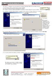
4.5.2 Installing the drivers<br />
• Download the required driver (driverUSB_785X.zip) (depending on your operating system) on our website<br />
(www.sefram.fr) or on theTR7836 CD.<br />
• Unzip the archive in your chosen directory.<br />
• After unzipping the drivers, connect the appliance to the PC by using a type A to mini B USB cable (available<br />
as an extra from SEFRAM under the number 978551100).<br />
• After connecting the appliance to the PC, the following screen appears : (if Windows Update is searching the<br />
driver, click on « Not this time » and on « Next ».)<br />
p. 26
– <strong>7851</strong>-<strong>7851</strong>C-<strong>7852</strong> –<br />
1) Select « Install from a list or specific location » and click on « Next ».<br />
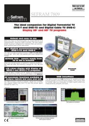
2) The following screen appears :<br />
3) Tick « Search for the best driver in these locations » and « Include this location in the search ».<br />
4) With the « Browse » button, select the directory to which you extracted the drivers.<br />
5) Click on « Next » and « Finish » when the installation is completed.<br />
• A second driver is necessary to make the interface work. Redo the procedure since step 1).<br />
To check that the installation is correct and see to which port the appliance is connected, here is the<br />
procedure to be followed :<br />
• Go to your driver (configuration panel System) .<br />
p. 27
– <strong>7851</strong>-<strong>7851</strong>C-<strong>7852</strong> –<br />
Under « Port (COM et LPT) » find the « USB Serial Port (COMX) » peripheral that represents your appliance.<br />
X represents its COM port number (3 in our case).<br />
If the installation did not go well, an exclamation mark appears on the « USB Serial » line or on the<br />
« USB serial port (COMX) » line and indicates a malfunctioning of the interface.<br />
It is important that you remember to which USB port the cable is connected.<br />
Always connect the appliance to the same port in order to avoid reinstalling<br />
the driver or changing the COM port number.<br />
p. 28
– <strong>7851</strong>-<strong>7851</strong>C-<strong>7852</strong> –<br />
4.5.3 Updating the software<br />
The embedded software can be updated to get new features developed by SEFRAM.<br />
• download from our web site (www.sefram.fr) , the update software 785X_vX.X.ZIP<br />
• unzip this file in your chosen directory<br />
• launch SETUP.EXE then follow the instructions<br />
• Connect the appliance to your PC (when appliance is off) through the USB link<br />
• Turn on the appliance<br />
• Launch FLASH785X on your PC (you can clic on your country flag to change the language).<br />
• Configure the USB link by choosing the right COM port (to find the right COM port for the appliance see<br />
above). Then launch loading (click on the yellow « smiley »)<br />
• Wait for the bar graph to be filled<br />
The software is loaded in your appliance. Error messages may appear, do not take account of this. At<br />
the end of the update, turn off and then turn on the appliance.<br />
p. 29
– <strong>7851</strong>-<strong>7851</strong>C-<strong>7852</strong> –<br />
p. 30
– <strong>7851</strong>-<strong>7851</strong>C-<strong>7852</strong> –<br />
5 AUTOSET Mode<br />
This mode permits to perform an automatic program search and to inform the current place. To access<br />
this mode, press the key :<br />
The lines displayed on this page depend on the wanted frequency bandwidth (line MODE) :<br />
Terrestrial Mode Satellite Mode<br />
Cable Mode<br />
After you have chosen a mode, use the up/down and left/right keys to move in the table. The central<br />
key on the sensitive wheel permits to confirm or to cancel an option.<br />
A red cross shows the para<strong>meter</strong>s that are not taken into account in searching. A green tick shows that<br />
a para<strong>meter</strong> is taken into account.<br />
Please remember that the more standards are selected, longer will be the search time.<br />
5.1 Terrestrial Mode<br />
This mode permits automatic search on the terrestrial frequency bandwidth.<br />
The table permits to choose :<br />
• Standards<br />
• Bandwidths<br />
• Remote supply<br />
p. 31
– <strong>7851</strong>-<strong>7851</strong>C-<strong>7852</strong> –<br />
5.2 Cable Mode<br />
This mode permits automatic search on the cable frequency bandwidth.<br />
The table permits to choose :<br />
• Standards<br />
• Constellations<br />
• Symbol rates<br />
5.3 Satellite Mode<br />
This mode permits automatic search on the satellite frequency bandwidth.<br />
The table permits to choose :<br />
• Standards<br />
• LNB bands<br />
• LNB polarizations<br />
• Symbol rates<br />
5.4 « Scan » menu key<br />
When you have correctly informed the table, click on the « scan » key to launch search.<br />
A warning message indicates that the current place will be crushed. If you<br />
want to keep the current place, modify the place number in the Para<strong>meter</strong>s<br />
page.<br />
Pressing YES deletes the current place. It will be filled with the new values of the found programs. The<br />
screen below shows the progressing search :<br />
When search is in progress, pressing « Stop » interrupts<br />
the search.<br />
The appliance goes automatically to the Measurement Map mode when search is completed or when<br />
the <strong>user</strong> stops search.<br />
p. 32
– <strong>7851</strong>-<strong>7851</strong>C-<strong>7852</strong> –<br />
6 Configuration of Places<br />
Pressing the key permits to access the PARAMETERS function :<br />
• Initialization of the data included in each Place<br />
• Initialization of the data included in each Setup<br />
• Choice of a Place among n places during a measurement session<br />
The lines displayed on the page below depend on the Frequency bandwidth selected for this place.<br />
Terrestrial Band 45 - 865 MHz Satellite Band 920 - 2150 MHz<br />
6.1 Para<strong>meter</strong>s<br />
‣ Selecting a place<br />
This choice can be made through a Place number (sensitive wheel or keyboard) or through the list of<br />
Places.<br />
Menu keys :<br />
• Name : Place name input (10 characters maxi)<br />
• List : Choice of the current Place among the list of Places.<br />
‣ Selecting a Frequency bandwidth for a Place<br />
Menu keys :<br />
• Ter. : terrestrial 45 -865 MHz with all standards of terrestrial TV<br />
• Sat. : satellite 920 - 2150 MHz with all standards of satellite TV<br />
‣ Modification of Thresholds (min./maxi) for each standard.<br />
Menu keys :<br />
• Modif. : displays the list of Thresholds for modification<br />
To move on this menu use the direction keys. To modify a Threshold use the sensitive wheel.<br />
Press a function key to complete the modification.<br />
‣ Modification of the Headers (that can be used with the TR7836 software).<br />
Menu keys :<br />
• Modif. : displays the list of Messages for modification<br />
p. 33
– <strong>7851</strong>-<strong>7851</strong>C-<strong>7852</strong> –<br />
To move on this menu use the direction keys. Data input starts by pressing a key on the alphanumerical<br />
keyboard.<br />
Yes/No : validates the printing of each message<br />
Press any function key to complete modification.<br />
‣ Choice of the Frequencies Map used in the instrument (Terrestrial Band only).<br />
Menu keys :<br />
• Modif. : displays the list of channels for modification<br />
• List : displays the list of the frequency map predefined in the instrument<br />
The modification can be performed either by using the rotary wheel or by the keypad.<br />
The Frequencies Map will be named ‘User defined’.<br />
It is necessary to choose the frequencies map corresponding to the area where the<br />
instrument is used so that you have the right correspondence frequency / channel.<br />
Caution: a change in a Frequency map will erase a possible plan 'User defined’ previously<br />
used: there is only one possible frequency channel correspondence.<br />
6.2 Setup list<br />
List of all Setups included in the current Place.<br />
Menu keys:<br />
• Modif : data input in a Setup<br />
• Delete. : to delete information for a Setup<br />
• Reset : to erase all Setups<br />
• S ^ : to move the selected setup to the line above<br />
• S v : to move the selected setup to the line below<br />
• Init : initialization of all Setups from the frequency map (one Channel per setup)<br />
Pressing 'Modif' key in the setup list will display all the information concerning the setup for modification.<br />
Press the direction keys to access the para<strong>meter</strong>s of the Setup.<br />
Each line corresponds to an initialization menu of the para<strong>meter</strong> concerned in the Setup.<br />
Each Setup is described according to its structure (see chapter 2) that depends on the Frequency<br />
band chosen for the Place.<br />
Press any function key to complete modification.<br />
p. 34
7 Spectrum Analyzer<br />
– <strong>7851</strong>-<strong>7851</strong>C-<strong>7852</strong> –<br />
Pressing the key gives access to the SPECTRUM ANALYZER function :<br />
• Graphic representation of frequency / amplitude for signals present at the instrument input<br />
Satellite Mode Terrestrial Mode<br />
The modifiable para<strong>meter</strong>s are the following :<br />
• Cursor : Fast positionings of the cursor, search for peaks<br />
• Span : Frequency span around the central frequency<br />
• RefLevel : Reference level (scale of amplitudes maximum value)<br />
• dB/div : Step of the amplitudes scale 5 dB or 10 dB<br />
• Setup : Pressing this key permits to switch from one setup to another by using the sensi<br />
tive wheel.<br />
• Polar : Change of polarization (horizontal, vertical, right, left) (satellite mode).<br />
• Channel : Pressing this key permits to switch from one channel to another by using the sensitive<br />
wheel (terrestrial mode).<br />
• Full : Full span mode that permits to have a maximum frequency span.<br />
• Auto : Automatic reference level<br />
The measurement cursor can be moved by using the sensitive wheel or the direction keys (RIGHT and<br />
LEFT).<br />
The input attenuator automatically positions itself according to the Reference level.<br />
The filter automatically positions itself according to the « span ».<br />
p. 35
– <strong>7851</strong>-<strong>7851</strong>C-<strong>7852</strong> –<br />
p. 36
– <strong>7851</strong>-<strong>7851</strong>C-<strong>7852</strong> –<br />
8 Normal Check satellite and Double LNB<br />
In Satellite band only. The check satellite mode allows a fast alignment of satellite<br />
dish by the initial choice of the satellite to be received.<br />
Pressing the key twice gives access to the CHECKSAT function when the current Place is<br />
in satellite band.<br />
The appliance has 30 preprogrammed<br />
satellite orbital positions<br />
in storage, each satellite possessing<br />
4 transponders.<br />
8.1 <strong>Sefram</strong>Sat software<br />
8.1.1 Installation<br />
You can download the <strong>Sefram</strong>Sat software on our website (www.sefram.fr).<br />
<strong>Sefram</strong>Sat software permits to inform correctly one or several satellites.<br />
Each satellite is characterized by 4 transponders.<br />
• Double-click on setup.exe file to install the software on your<br />
PC.<br />
• Launch <strong>Sefram</strong>Sat software (Start->Programs-><strong>Sefram</strong>SAT).<br />
By default, the software is delivered with a valid satellite list installed in the <strong>Sefram</strong>Sat installation directory.<br />
p. 37
– <strong>7851</strong>-<strong>7851</strong>C-<strong>7852</strong> –<br />
Example : how to open « europe.sat » file :<br />
Satellites<br />
4 transponders<br />
Each satellite is characterized by :<br />
• its name<br />
• its position<br />
• its band (C or Ku)<br />
• 4 transponders<br />
Each transponder is characterized by :<br />
• a frequency<br />
• a standard<br />
• a Symbol rate<br />
• a polarity<br />
8.1.2 How to use <strong>Sefram</strong>Sat<br />
Set <strong>Sefram</strong>Sat software depending on the appliance you are using :<br />
• « Instruments » permits to choose the target appliance.<br />
• « Port » permits to choose the COM port where the appliance is installed (see paragraph « connecting the<br />
appliance to a PC » : 4.5).<br />
The different controls permitted by <strong>Sefram</strong>Sat are :<br />
• « File » then « Open » permits to open a *.sat that includes a satellite list.<br />
• « File » then « Save » permits to save all the defined satellites.<br />
p. 38
– <strong>7851</strong>-<strong>7851</strong>C-<strong>7852</strong> –<br />
Sends the list of satellites<br />
contained in the<br />
appliance to <strong>Sefram</strong>Sat<br />
software.<br />
Sends the list of satellites<br />
contained in <strong>Sefram</strong>Sat<br />
software to the<br />
appliance.<br />
Addition of a satellite to<br />
the current map.<br />
Deletes the selected<br />
satellite from the current<br />
map.<br />
• <strong>Sefram</strong>Sat permits to characterize completely one or several satellites : each para<strong>meter</strong> can be modified either<br />
directly by keyboarding its value or by selecting from a drop-down list.<br />
Example : How to send the « europe.sat » file to the 7855 appliance.<br />
-Click on « instrument » and tick « <strong>7851</strong>-7856 »<br />
-Click on « port » and select the right COM port.<br />
-Click on « file-> open » and search the « europe.sat » file.<br />
-Click on<br />
to transmit the satellite list to the appliance.<br />
8.2 Checksat mode interface<br />
Satellite’s name +<br />
Position<br />
LNB current<br />
assumption<br />
Overall quality annunciator<br />
Transponder 2 information<br />
p. 39
– <strong>7851</strong>-<strong>7851</strong>C-<strong>7852</strong> –<br />
Reception level (%)<br />
Quality (%)<br />
Level and quality<br />
bargraph<br />
Transponder’s frequency<br />
Transponder’s rate<br />
8.3 Normal checksat<br />
Band/ polarization<br />
Transponder’s standard<br />
Permits to direct a dish towards a satellite.<br />
Menu keys :<br />
• : Modification of para<strong>meter</strong>s for transpondeur 1, 2, 3 or 4.<br />
• : Double checksat mode.<br />
8.3.1 Normal checksat information<br />
Operating mode :<br />
1/ Connect the dish towards the appliance and turn it on.<br />
2/ Validate remote supply :<br />
-The « VDC » LED on the front panel flashes.<br />
-Check the LNB remote supply (approximately<br />
200 mA).<br />
3/ Check satellite :<br />
- Select the satellite to be checked from the list<br />
(by using the rotary wheel).<br />
4/ Slowly connect the dish until you get the maximum of level and you can hear the locking melody.<br />
5/ Adjust the LNB to get the best quality (against polarization).<br />
You can hear a melody as soon as the first transponder is found and then you can hear beeps. These<br />
beeps are becoming shorter when quality increases.<br />
If the appliance is not synchronized on any transponder the quality annunciator is red.<br />
p. 40
– <strong>7851</strong>-<strong>7851</strong>C-<strong>7852</strong> –<br />
If the appliance is synchronized and if the reception quality is average the quality annunciator is orange.<br />
If the appliance is synchronized and if the reception quality is good the quality annunciator is yellow.<br />
Caution : To identify correctly a satellite, the appliance must be synchronized on<br />
the 4 transponders.<br />
However certain transponders are modified regularly. Please see the satellite’s<br />
frequency map when it seems that a transponder is not working.<br />
Some commutators or LNB work only with DISEqC. In this case, position<br />
the band (LO) and the DISEqC polarization on the LNB-DISEqC configuration<br />
page (Caution : By using DISEqC, checksat is slowed down).<br />
8.4 Double checksat<br />
This mode permits to direct a double LNB by checking 4 transponders on your 2 chosen satellites.<br />
It works the same way as the normal checksat Mode.<br />
Satellite A<br />
Satellite B<br />
Satellite A is on the left side of the screen and Satellite B is on the right side.<br />
Menu keys :<br />
• : Modification of para<strong>meter</strong>s for Satellite A’s transponder 1, 2, 3 or 4.<br />
• : Modification of para<strong>meter</strong>s for Satellite B’s transponder 1 (T5), 2<br />
(T6), 3 (T7) or 4 (T8).<br />
The left/right direction keys permit to switch from Satellite A to Satellite B and vice versa. The sensitive<br />
wheel permits to modify the current satellite (change of satellite according to the list sent by <strong>Sefram</strong>Sat<br />
software). To exit from this mode, press any function key.<br />
p. 41
– <strong>7851</strong>-<strong>7851</strong>C-<strong>7852</strong> –<br />
8.5 Modification of a transponder’s para<strong>meter</strong>s<br />
Pressing one of the Tx keys permits to modify the transponder associated with the number x :<br />
T1->Modification of transponder 1 associated with satellite A.<br />
T2-> Modification of transponder 2 associated with satellite A..<br />
T3-> Modification of transponder 3 associated with satellite A..<br />
T4-> Modification of transponder 4 associated with satellite A..<br />
T5-> Modification of transponder 1 associated with satellite B.<br />
T6-> Modification of transponder 2 associated with satellite B.<br />
T7-> Modification of transponder 3 associated with satellite B.<br />
T8-> Modification of transponder 4 associated with satellite B.<br />
For every line of the mini-page there is a different menu :<br />
Click on the<br />
key to go back to normal or double checksat.<br />
Activating or deactivating a transponter permits to accelerate the search for active<br />
transponders.<br />
You can modify the transponders either directly in the appliance, or by using <strong>Sefram</strong>-<br />
Sat.<br />
Please, choose transponders with high rate in order to get a fast alignment of satellite<br />
dish.<br />
p. 42
9 Image and Sound<br />
– <strong>7851</strong>-<strong>7851</strong>C-<strong>7852</strong> –<br />
Pressing the<br />
key gives access to the IMAGE AND SOUND function.<br />
9.1 Analog TV<br />
Display of terrestrial analog images.<br />
FM radios.<br />
Sound, brightness, colour, contrast controls.<br />
Direct modification of the current setup.<br />
Full screen mode.<br />
Display of the synchro signal.<br />
Menu keys :<br />
• : Setting of the volume with the sensitive wheel.<br />
• : Setting of the brightness with the sensitive wheel.<br />
• : Setting of the contrast with the sensitive wheel.<br />
• : Setting of the colour saturation with the sensitive wheel.<br />
• : Modification of the number of the currently displayed program.<br />
• : Full screen mode.<br />
• : Display of synchro signal.<br />
9.1.1 Volume and screen settings<br />
Pressing one of the volume or screen setting keys makes a bargraph appear. The sensitive wheel permits<br />
to increase or decrease the volume depending on the direction of rotation.<br />
p. 43
– <strong>7851</strong>-<strong>7851</strong>C-<strong>7852</strong> –<br />
9.1.2 Full Screen Mode<br />
The different full screen modes are described below :<br />
4/3 full screen mode : no distortion for a 4/3 transmission.<br />
Cinema full screen mode : no distortion<br />
for a 16/9 transmission.<br />
Wide full screen mode : horizontal distorsion<br />
for a 4/3 transmission.<br />
p. 44
– <strong>7851</strong>-<strong>7851</strong>C-<strong>7852</strong> –<br />
Wide+ full screen mode : horizontal + vertical<br />
distortion for a 4/3 transmission.<br />
16/9 full screen mode : horizontal distortion<br />
for a 4/3 transmission.<br />
9.1.3 Synchro signal<br />
The synchro signal (vertical) is inlaid in the picture below.<br />
9.2 MPEG2 TV<br />
• MPEG2 DVB-T/H, DVB-S, DSS, DVB-S2, DVB-C.<br />
• Choice of the MPEG2 service.<br />
Menu keys :<br />
• : Setting of the volume with the sensitive wheel.<br />
p. 45
– <strong>7851</strong>-<strong>7851</strong>C-<strong>7852</strong> –<br />
• : Setting of the brightness with the sensitive wheel.<br />
• : Setting of the contrast with the sensitive wheel.<br />
• : Setting of the colour saturation with the sensitive wheel.<br />
• : Modification of the number of the currently displayed program.<br />
• : Full screen mode. (See 9.1.2)<br />
• : Services display.<br />
9.2.1 Services list<br />
Get and display the Services included in the MPEG2 multiplex.<br />
Choice of the service with the sensitive wheel or with the up/down direction keys.<br />
Confirmation of the chosen service by pressing the<br />
key.<br />
9.2.2 Access rights / access card<br />
Please find the access card at the back of the appliance (this extra cannot be found on the <strong>7851</strong> model).<br />
When the channel displayed in TV mode is encrypted, the appliance automatically checks on the card interface<br />
if there is a decoding key.<br />
If you don’t insert the right access card, you could not watch the encrypted channels.<br />
p. 46
– <strong>7851</strong>-<strong>7851</strong>C-<strong>7852</strong> –<br />
10 Level / power measurement<br />
Press the key to access to the LEVEL MEASUREMENT function :<br />
• Perform a level measurement for a specified frequency with a detection and a filter appropriate to standard.<br />
In terrestrial band, for a <strong>user</strong> socket the level must lie between 50 and 66<br />
dBµV in FM, between 35 and 70 dBµV in COFDM and between 57 and 74<br />
dBµV in any other case.<br />
In satellite band, for a <strong>user</strong> socket the level must lie between 47 and 77<br />
dBµV.<br />
10.1 Para<strong>meter</strong>s<br />
Every menu depends on the para<strong>meter</strong> in reverse video. The different para<strong>meter</strong>s are :<br />
• Setup # : Selected setup.<br />
This choice can be made by using the sensitive wheel, the keyboard or the list of Setups.<br />
• Frequency : Selected frequency.<br />
You can change the selected frequency by using the sensitive wheel, the keyboard or the frequencies<br />
Map.<br />
Menu keys :<br />
Map : choice of a frequency in the frequencies Map.<br />
• Channel : Selected channel (in terrestrial band only)<br />
This choice can be made by using the sensitive wheel, the keyboard or the frequencies Map.<br />
Menu keys :<br />
6 MHz, 7 MHz, 8 MHz : choice of the COFDM (DVB-T/H) bandwidth.<br />
Map :<br />
choice of the Channel in the Frequencies Map.<br />
p. 47
– <strong>7851</strong>-<strong>7851</strong>C-<strong>7852</strong> –<br />
• Standard : Selected standard.<br />
This choice is made by using the menu keys (they show all the available standards).<br />
Menu keys :<br />
All available standards on the current frenquency Band.<br />
• Audio : Selected audio Mode.<br />
This choice is made by using the menu keys (they show all the available Modes).<br />
In Terrestrial Band :<br />
Mono, Stéréo and NICAM<br />
• Band / Polar. : Choice of Bandwidth and LNB polarization (Local Oscillator) (in Satellite band only)<br />
Bandwidth :<br />
Low :set the LNB on LO1<br />
High :<br />
set the LNB on LO2<br />
This choice is made accordingly to the type of LNB that you have selected in PARAMETERS page<br />
(Function key LNB-DiSEqC).<br />
Caution: All information concerning LNB and positioner is transferred through the<br />
remote supply; 22 kHz modulation or DiSEqC is combined with the DC supply<br />
generated by the appliance.<br />
Polarization :<br />
Vert. :<br />
LNB Polarization is switched to Vertical mode.<br />
Hor. :LNB Polarization is switched to Horizontal mode.<br />
Right :<br />
LNB Polarization is switched to Right mode.<br />
Left : LNB Polarization is switched to Left mode.<br />
This choice is made accordingly to the type of LNB that you have selected in PARAMETERS page, line<br />
LNB-DiSEqC.<br />
10.2 Measurements according to Standard<br />
The appliance performs various measurements depending on the selected standard.<br />
The possible measurements are as follows: Average measure, Peak measure and Power measure.<br />
10.2.1 Terrestrial Band<br />
The appliance automatically performs level measurements on Video Carrier and on 1 or 2 Audio Carriers<br />
(depending of the selected audio mode).<br />
The table below shows the different types of measures and the audio carriers frequencies for each<br />
Standard.<br />
p. 48
– <strong>7851</strong>-<strong>7851</strong>C-<strong>7852</strong> –<br />
Standard video carrier measure audio carriers<br />
Mono stéréo NICAM<br />
BG negative, AM peak FM FM DQPSK<br />
5,5 MHz 5,74 MHz 5,85 MHz<br />
DK negative, AM peak FM FM DQPSK<br />
6,5 MHz 6,258 MHz 5,85 MHz<br />
I positive, AM peak FM DQPSK<br />
6,0 MHz 6.552 MHz<br />
L positive, AM peak AM DQPSK<br />
6,5 MHz 5.85 MHz<br />
MN negative, AM peak FM FM<br />
4,5 MHz 4,72 MHz<br />
DVB-C digital power<br />
MCNS digital power<br />
DVB-T/H digital power<br />
FM FM average<br />
Carrier Non modulated average<br />
The appliance shows the video carrier level, the video-audio ratio(s) and the C/N ratio.<br />
The display is made of 1 to 4 measures and bargraph.<br />
The audio carriers are always measured in Average measure.<br />
10.2.2 Satellite Band<br />
standard Video carrier measure<br />
PAL FM peak<br />
SECAM FM peak<br />
NTSC FM peak<br />
DVB-S digital power<br />
DSS digital power<br />
DVB-S2 digital power<br />
p. 49
– <strong>7851</strong>-<strong>7851</strong>C-<strong>7852</strong> –<br />
p. 50
– <strong>7851</strong>-<strong>7851</strong>C-<strong>7852</strong> –<br />
11 Error rate measurement<br />
To access to the error rate measurement function, press twice the<br />
LEVEL function key.<br />
The displayed measures are BER (Bit Error Rate), UNC (Uncorrected Packets)<br />
and MER (Modulation Error Rate) in DVB-T/H, DVB-C, DVB-S or NICAM. In DVB-S2, LDPC, BCH, PER<br />
and MER are displayed.<br />
If the BER or VBER error rate is higher than 1 e -4, the bargraph is yellow ; if there<br />
are lost packages, it is red.<br />
You can access to these measurements if one of the following standards is in progress in the LEVEL MEA-<br />
SUREMENT page :<br />
DVB-S, DSS<br />
DVB-S2<br />
DVB-C (<strong>7851</strong>C only)<br />
DVB-T/H<br />
NICAM<br />
11.1 Para<strong>meter</strong>s<br />
The number and the meaning of the displayed para<strong>meter</strong>s depend on the Standard selected.<br />
The Setup, Frequency, Channel, LNB Band and LNB Polarization para<strong>meter</strong>s are the same as in the<br />
LEVEL MEASUREMENT screen (see chapter « Level / power measurement » ).<br />
The Frequency para<strong>meter</strong> also gives access to :<br />
• A "Scan+" and "Scan-" function that searches for channels for the current standard.<br />
• Functions linked to the "Posit." Positioner (in Satellite band if there is a positioner) :<br />
• < West : moves the dish westwards.<br />
• East > : moves the dish eastwards.<br />
• Stop : no move.<br />
• Store : saves the current position in the current position number.<br />
• Calcul. : Recalculation order of the positioner’s other positions.<br />
A long press on the “ “ keys launches a continuous movement.<br />
Press " Stop " to stop this action.<br />
The other para<strong>meter</strong>s depend on the type of digital standard DVB-S, DVB-S2, DSS, DVB-T/H, DVB-C or<br />
NICAM.<br />
"Sync ?" shows that the signal is missing or non-locked, check that the signal<br />
and the remote supply are not missing, the modulation para<strong>meter</strong>s and the LNB<br />
and DiSEqC para<strong>meter</strong>s in satellite band.<br />
The "
– <strong>7851</strong>-<strong>7851</strong>C-<strong>7852</strong> –<br />
11.2 DVB-C<br />
Display of the following measures :<br />
• BER : error rate before Reed Solomon<br />
• UNC : error rate after Reed Solomon (lost packets)<br />
• MER : modulation error rate<br />
BER : 'bit' error rate<br />
Number of wrong bits / number of transmitted bits ratio during Measuring time.<br />
UNC : 'packet' error rate<br />
Number of wrong packets / number of transmitted packets ratio during Measuring time.<br />
Note : A QAM (DVB-C) packet is made of 204 bytes ; a packet is 'wrong' if it has more than 8 wrong bytes<br />
(correction with Reed Solomon coding).<br />
11.3 DVB-S, DSS<br />
Display of the following measures :<br />
• CBER : error rate before Viterbi (estimated)<br />
• VBER : error rate after Viterbi<br />
• UNC : error rate after Reed Solomon (lost packets)<br />
• MER : modulation error rate<br />
xBER : 'bit' error rate<br />
Number of wrong bits / number of transmitted bits ratio during Measuring time.<br />
UNC : 'packet' error rate<br />
Number of wrong packets / number of transmitted packets ratio during Measuring time.<br />
Note : A QPSK (DVB-S) packet is made of 204 bytes ; a packet is 'wrong' if it has more than 8 wrong bytes<br />
(correction with Reed Solomon coding). In DSS, a packet is made of 146 bytes.<br />
11.4 DVB-S2<br />
Display of the following measures :<br />
• LDPC : error rate before LDPC<br />
• BCH : error rate after LDPC<br />
• PER : error rate after BCH (lost packets)<br />
• MER : modulation error rate<br />
Note :<br />
LDPC : low density parity check<br />
BCH : Bose Chauhuri Houquenohem<br />
The Viterbi + Reed Solomon concatenation of the correction of the DVB-S is replaced in DVB-S2 by the<br />
LDPC and BCH concatenation.<br />
p. 52
– <strong>7851</strong>-<strong>7851</strong>C-<strong>7852</strong> –<br />
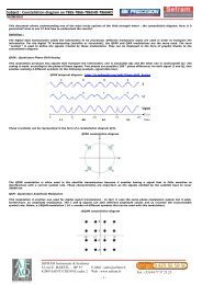
11.5 DVB-T/H (COFDM)<br />
Display of the following measures:<br />
• CBER : error rate before Viterbi<br />
• VBER : error rate after Viterbi<br />
• UNC : error rate after Reed Solomon (lost packets)<br />
• MER : modulation error rate<br />
xBER : 'bit' error rate<br />
Number of wrong bits / number of transmitted bits ratio during Measuring time.<br />
UNC : 'packet' error rate<br />
Number of wrong packets / number of transmitted packets ratio during Measuring time.<br />
Note : a COFDM packet is made of 204 bytes ; a packet is 'wrong' if it has more than 8 wrong bytes<br />
(correction with Reed Slomon coding).<br />
Para<strong>meter</strong>:<br />
• Modulation : Type of detected Modulation<br />
Automatically displays :<br />
the number of carriers (2K / 8 K…)<br />
the constellation (QPSK, 16QAM, 64QAM…)<br />
the guard interval (1/32, 1/16, 1/8, ¼…)<br />
the Viterbi rate (1/2, 2/3, 3/4, 5/6, 7/8…)<br />
In case of hierarchical modulation use the HP and LP keys to select the stream to be measured. The Info+<br />
menu key (para<strong>meter</strong> modulation) gives access to the following additional information :<br />
• the frequency offset<br />
• the HP stream’s Viterbi rate<br />
• the LP stream’s Viterbi rate<br />
• the hierarchical mode level<br />
• the spectral inversion of the signal<br />
• the presence and relative level of a co-frequent analog<br />
channel<br />
• the presence and relative levels of echos out of the<br />
guard rate<br />
• the cell identifier<br />
11.6 NICAM<br />
Content of the detected NICAM carrier. Automatically displays :<br />
• mono<br />
• stereo<br />
• two mono channels (bilingual)<br />
• data<br />
In "two mono channels", for example a bilingual transmission, use the "Sound 1" and " Sound 2" menu<br />
keys to select the sound to be demodulated.<br />
p. 53
– <strong>7851</strong>-<strong>7851</strong>C-<strong>7852</strong> –<br />
The error rate measurement function is long if rate is low.<br />
p. 54
– <strong>7851</strong>-<strong>7851</strong>C-<strong>7852</strong> –<br />
12 Impulse response (DVB-T/H only)<br />
Only for <strong>7852</strong>.<br />
To access to the impulse response function, press third the<br />
LEVEL function key.<br />
The appliance displays the impulse response for the signal in progress.<br />
This function permits to display the possible echos affecting the received signal. Relative amplitude<br />
in dB and delay in µs (distance in km or in mile) compared to the main signal (line 0) can be<br />
estimated. The yellow line represents the end of guard rate, the echos (lines) that are situated<br />
beyond this line disrupt reception and must be as low as possible : direct correctly your antenna<br />
or use a more directive antenna.<br />
You can change the zoom and the unit used for display by using the menu keys :<br />
• Zoom8 …Zoom1 : analysis full or partial range<br />
• Unité : unit selection : µs, kilometre or mile.<br />
p. 55
– <strong>7851</strong>-<strong>7851</strong>C-<strong>7852</strong> –<br />
p. 56
– <strong>7851</strong>-<strong>7851</strong>C-<strong>7852</strong> –<br />
13 LNB - DISEqC<br />
To access to the installation configuration press the<br />
function key.<br />
13.1 Satellite Band<br />
Configuration para<strong>meter</strong>s :<br />
• Remote supply : remote supply on / off<br />
• LO1 Frequency : LO frequency LNB low band<br />
• LO2 Frequency: LO frequency LNB high band<br />
• LO selection : band switching on the LNB (22 kHz, ToneBurst or DiSEqC)<br />
• Polar selection : polarization switching on the LNB (13/18V ou DiSEqC)<br />
• Switch : presence and type of a commutator (No, ToneBurst, 22 kHz or DiSEqC)<br />
• Satellite : commutator position (SAT A, SAT B, SAT C or SAT D)<br />
• Positioner : positioner presence (Yes / No)<br />
• Satellite # : current position (from 1 to 127 positions precharged in the positioner)<br />
13.2 Terrestrial band<br />
Configuration para<strong>meter</strong>s:<br />
• Remote supply : remote supply on / off. Selection of the remote supply voltage among 5V, 13V, 18V.<br />
p. 57
– <strong>7851</strong>-<strong>7851</strong>C-<strong>7852</strong> –<br />
p. 58
– <strong>7851</strong>-<strong>7851</strong>C-<strong>7852</strong> –<br />
14 Configuration<br />
To access to the appliance general CONFIGURATION, press the key :<br />
• language, date and time<br />
• LCD lighting, beep volume<br />
• measurement unit, corrections<br />
• memories<br />
• initializations<br />
14.1 Language, date, time, LCD and beep<br />
To change these para<strong>meter</strong>s, use the menu keys.<br />
Caution : By reducing the screen brightness, you can gain autonomy but this process can also<br />
cause backlighting flashings.<br />
Line LCD : The « auto » key permits to activate / deactivate the energy saving function (it consists in the<br />
extinction of the backlight after a few minutes).<br />
14.2 Measurement unit<br />
Menu keys :<br />
• dBµV : 0 dBµV is equivalent to 1 µV<br />
• dBmV : 0 dBmV is equivalent to 1 mV<br />
• dBm : 0 dBm is equivalent to 274 mV : 1 mW in a 75 ohms impedance.<br />
• V : measurement in V, mV or µV depending on the level.<br />
14.3 Correction coefficients<br />
They are used to compensate for cable losses to adjust an external attenuator, amplifier or antenna.<br />
p. 59
– <strong>7851</strong>-<strong>7851</strong>C-<strong>7852</strong> –<br />
Menu keys :<br />
• Modif : list of coefficients for modification<br />
• Yes/No : activates / desactivates correction<br />
Modification of coefficients :<br />
• F- : decreases the frequency of the selected<br />
coefficient<br />
• F+ : increases the frequency of the selected<br />
coefficient<br />
• C- : decreases the correction value of the<br />
selected coefficient<br />
• C+ : increases the correction value of the<br />
selected coefficient<br />
• Init. : initializes to 0 the correction value of<br />
the selected coefficient<br />
Coefficients act in LEVEL MEASUREMENT and in MEASUREMENT MAP.<br />
14.4 Memories<br />
14.4.1 Folders<br />
Files are divided into different folders so they are easier to manage.<br />
The number of files in every folder and the percentage they occupy appear on the right.<br />
The ' TOTAL ' folder shows the whole internal memory occupied.<br />
Menu keys :<br />
• Dir : list of the files in the folder<br />
• Reset : erases the folder<br />
14.4.2 File list<br />
To display the file list in the selected folder , press the menu key ' Dir '.<br />
p. 60
– <strong>7851</strong>-<strong>7851</strong>C-<strong>7852</strong> –<br />
The displayed information is as follows :<br />
• File number<br />
• File name and extension (type)<br />
• Frequency bandwidth where the file has been saved<br />
• Date and time of backup<br />
Menu keys :<br />
View :<br />
Delete :<br />
displays the file selected<br />
deletes the file selected<br />
14.5 Initializations<br />
p. 61
– <strong>7851</strong>-<strong>7851</strong>C-<strong>7852</strong> –<br />
Initializations :<br />
• Places nb. : selection of the number of Places in the appliance<br />
• Reset actual place : erases all information about the current Place<br />
• Copy channels->setups : initializes the name of setups with ' CANAL xx '<br />
• Copy setups->measurement map : copies all Setups in the Measuremement map<br />
• Reset every place : erases all information about all Places<br />
For a better security, all these operations must be double-confirmed.<br />
p. 62
– <strong>7851</strong>-<strong>7851</strong>C-<strong>7852</strong> –<br />
15 Save / Recall<br />
To SAVE or RECALL configurations or measures, press the<br />
key.<br />
After transfert, the saved measures will make it possible to create measurements<br />
reports on a PC by using the TR7836 transfert software.<br />
A pop up window is displayed over the current screen and shows a file name by default 'MEM xxx'.<br />
Menu keys :<br />
• Name : change of the file name (alphanumerical data input : 8 characters max)<br />
• Dir. : list of the files already saved<br />
• Save : saves<br />
• Recall : recalls<br />
Two types of files are generated :<br />
• ' .TXT ' extension : configuration and numerical measures file<br />
• ' .DRW ' extension : graphical measures file<br />
Types of files according to the screen currently displayed :<br />
• PARAMETERS : TXT<br />
• LEVEL MEASUREMENT :digital display : TXT<br />
• MEASUREMENT MAP : digital display: TXT<br />
• SPECTRUM : whole screen : TXT, curve only : DRW<br />
• BER/MER : digital display : TXT<br />
• IMPULSE RESPONSE : TXT<br />
• CONFIGURATION : total configuration : TXT<br />
p. 63
– <strong>7851</strong>-<strong>7851</strong>C-<strong>7852</strong> –<br />
15.1 Save<br />
You can save directly a file by using the ' MEM xxx ' name (number auto-incrementation until 1000) or modify<br />
it.<br />
After you input the file name, press the menu key' Save '.<br />
Caution : Switching the appliance off may take a few seconds because information is saved on<br />
flash memory while shutting down the appliance.<br />
15.2 Recall<br />
You can recall directly a file by using its name or searching for it in the list of files through the ' Dir ' menu<br />
key.<br />
The ' Dir ' menu key displays the list of files with the following characteristics :<br />
• Files saved on the same page (see types of files above)<br />
• Files saved on the same Frequency bandwidth (in order not to recall the files saved on another frequency<br />
bandwidth)<br />
Select the file in the displayed list, then recall it by pressing the ' Recall ' menu key.<br />
The file is recalled and the" Display memory mode " message is displayed on the menu keys.<br />
Press a function key to quit 'Memory mode' and to restart measurements.<br />
15.3 Save / Recall Measurement Map<br />
Saving the Measurement Map is made up of the list of Setups found in the Map and associated with the<br />
measures (V, A1, A2).<br />
Only the numbers of Setups in the Place are saved : Frequency information, Channel and Standard are<br />
displayed in the list of Setups and the Frequency map of the current Place.<br />
Caution : If you recall a Measurement Map saved under another Place or if you<br />
modify the list of Setups in the Place, the Setup - Frequency - Standard – measures<br />
correspondence will be lost ! Besides, if the Measurement map for the Place<br />
has been modified, the displayed channels will not correspond to the measures.<br />
15.4 Spectrum curve superposition<br />
Concerning spectrum, the Save / Recall function gives 2 types of files (TXT and DRW) and the<br />
« overwrite ». Mode.<br />
The TXT file contains the total spectrum configuration and its curve as well.<br />
The DRW file contains the curve only. Recalling a DRW file superposes the saved curve to the current<br />
scanning (in red) if ' Overwrite ' is programmed on ' Yes '.<br />
p. 64
– <strong>7851</strong>-<strong>7851</strong>C-<strong>7852</strong> –<br />
Switching ' Yes / No ' in the ' Overwrite ' mode permits to display or not this curve in superposition.<br />
p. 65
– <strong>7851</strong>-<strong>7851</strong>C-<strong>7852</strong> –<br />
p. 66
– <strong>7851</strong>-<strong>7851</strong>C-<strong>7852</strong> –<br />
16 Measurement map<br />
To access to the MESAUREMENT MAP function, press the key :<br />
• Automatic measurements for different setups and out of tolerance measurements.<br />
• Digital display<br />
Caution : By using the index (located above the menu keys), you can follow the<br />
measurements in progress. Please wait for the index to perform a complete scan<br />
before you start storing your measurements.<br />
16.1 Entering / changing a setup number<br />
You can select the Setups to be scanned by entering the Setup numbers in the Measurement map.<br />
The selected line is displayed on the reverse video and is highlighted in the box" n° of the Measurement<br />
map.<br />
The name and number of Setup are displayed on the first line of the page.<br />
Enter the Setups to scan in the list of setups or use directly the numerical keyboard.<br />
You can move on the Measurement map by using the sensitive wheel or the direction keys.<br />
The number of the page currently displayed is indicated at the bottom of the screen, on the left ( n / 10).<br />
Menu keys :<br />
• Delete : deletes the Setup of the box selected<br />
• List : selection of a Setup from the list of Setups<br />
• Sort : sorts the Setups of the Measurement map (see below)<br />
• Reset : erases the whole map<br />
• Init. : copies the setups into the map<br />
p. 67
– <strong>7851</strong>-<strong>7851</strong>C-<strong>7852</strong> –<br />
16.2 Automatic sorting<br />
To sort the setups of the Measurement map, press the menu key " Sort ". They can be sorted out :<br />
• In ascending Setup number order<br />
• In ascending frequency order<br />
Alternately every time you press the key.<br />
16.3 Out of tolerance values<br />
Numerical values are displayed in color according to the Thresholds programmed in PARAMETERS, line<br />
Thresholds :<br />
• Red for values under the minimum Threshold or over the maximum Threshold.<br />
• Green for the values between these two Thresholds<br />
16.4 Graphic display<br />
By pressing twice the MEASUREMENT MAP function key, you can display the Measurement map in a<br />
graph.<br />
It is displayed in one screen ; the histogram widths are automatically fitted according to the number of Setups<br />
included in the Measurement map.<br />
The blue cursor shows a Setup and displays its number and its name on the first line of the page.<br />
This Setup’s video carrier level is displayed at the bottom on the left.<br />
You can move the cursor by using the sensitive wheel.<br />
A " tilt " measure (attenuation in the bandwidth) can be performed by moving 2 cursors with the menu<br />
keys :<br />
• : moves the tilt reference to the right<br />
• : moves the tilt cursor to the right<br />
p. 68
– <strong>7851</strong>-<strong>7851</strong>C-<strong>7852</strong> –<br />
The " tilt " measure is displayed at the bottom and on the right of the page.<br />
The histograms are displayed in color depending on the thresholds programmed in the PARA-<br />
METERS page, line Thresholds :<br />
• red for values lower than the minimum Threshold or higher than the maximum Threshold.<br />
• green for values between these two Thresholds.<br />
The audio carriers’ levels are added on the associated video carrier histogram, according to the colors in<br />
the legend at the top and on the right of the page.<br />
If one of the Audio carriers is higher than the programmed minimum or maximum Threshold, the whole<br />
histogram is displayed in red.<br />
p. 69
– <strong>7851</strong>-<strong>7851</strong>C-<strong>7852</strong> –<br />
p. 70
– <strong>7851</strong>-<strong>7851</strong>C-<strong>7852</strong> –<br />
17 Messages<br />
The appliance displays messages while it is working.<br />
17.1 Warning messages<br />
« BATTERY : DISCHARGED » : The battery is discharged, the appliance will automatically go off in a few<br />
minutes.<br />
« REMOTE SUPPLY FAULT » : Remote supply fault : a voltage is already on the cable or current is already<br />
exceeding the maximum value.<br />
Confirmation request for important action.<br />
17.2 Error messages<br />
Pressing a function key that is not available in the appliance<br />
p. 71
– <strong>7851</strong>-<strong>7851</strong>C-<strong>7852</strong> –<br />
The appliance tries to perform a level measurement out of these possibilities (for example an Audio measurement<br />
with a 865 MHz video carrier).<br />
Impossible to Save/Recall here.<br />
2 nd press on the level key : The appliance tries to perform an error rate measurement with a Standard different<br />
DVB-C, DVB-S, DVB-S2, DVB-T/H or NICAM.<br />
17.3 Failure messages<br />
« PROTECTION OVERHEATS ACTIVATED ,LET THE INSTRUMENT COOL »: If the internal temperature<br />
in the appliance is over 60°C : change to protection mode.<br />
p. 72
– <strong>7851</strong>-<strong>7851</strong>C-<strong>7852</strong> –<br />
If a message in red appears on the menu keys, contact SEFRAM technical support :<br />
e-mail : support@sefram.fr<br />
p. 73
– <strong>7851</strong>-<strong>7851</strong>C-<strong>7852</strong> –<br />
p. 74
– <strong>7851</strong>-<strong>7851</strong>C-<strong>7852</strong> –<br />
18 Maintenance<br />
In order to comply with the use requirements ad in order to preserve the whole characteristics, this equipment<br />
needs a minimum of maintenance.<br />
Consequence Recommended cheking periodicity<br />
Recommended<br />
limit of use<br />
BATTERY Reduction autonomy duration 200 cycles<br />
charge/discharge<br />
or 2 years<br />
Protection bag Bad protection and equipment<br />
breaking<br />
-For each use.<br />
-check of the strap’s posture.<br />
Backlight screen Reduction of visual level 2 years<br />
Metrological fitting/checking<br />
Wrong or erroneous measures Once a year 18 months<br />
CONNECTIQUE Wrong or erroneous measures At every measure<br />
The manufacturer’s recommendations do not commit SEFRAM I.S.’s responsability.<br />
They allow to ensure the best use possible of the characteristics and its preservation.<br />
Routine maintenance :<br />
The maintenance limits itself to the external cleaning of the equipment. The other operations require a<br />
qualified staff.<br />
Disconnect the equipment before any intervention.<br />
Do not let water enter in the equipment in order to avoid electric discharge risks.<br />
Regularly clean the equipment following the instructions here under :<br />
- use soapy water to clean it.<br />
- Do not use any product out of petrol, benzine, alcohol (if you do so, silk-screen printings will be damaged).<br />
- Wipe with a soft and nonpilled rag.<br />
- use a non static product, and a product without solvent to clean the sreen.<br />
For the bag :<br />
- Clean it with a clean rag, and do not use water.<br />
- Using solvents is totally forbidden.<br />
p. 75
– <strong>7851</strong>-<strong>7851</strong>C-<strong>7852</strong> –<br />
INFORMATION ABOUT LCD WITH ACTIV SCREEN MATRIX<br />
Your SEFRAM's Field Strength Meter is equipped with a LCD activ screen matrix.<br />
This screen is supplied by several known for manufacturers. In actual technical conditions of fabrication,<br />
manufacturers are not able to insure 100% of well functioning of the pixels in display area.<br />
They specified defective number of pixels on screen surface.<br />
SEFRAM's quality service conditionned assembly of the screen of your instrument to the respect of acceptation<br />
conditions of these manufacturers.<br />
ZONE B<br />
(diagonale 12.5 cm)<br />
ZONE A<br />
(diagonale 7.5 cm)<br />
Acceptation criteria :<br />
Zone A (central area) : less than 5 defective pixels and less than 3 pixels contiguous.<br />
Zone B (total surface of the screen) : less than 9 defective pixels on all display surface when zone A condition<br />
is respected.<br />
We mean by defective pixel a screen point which stay switched off or which light on a different color than<br />
the awaited one.<br />
The contractual warranty is not applicable on your <strong>field</strong> <strong>strength</strong> <strong>meter</strong> if the above defined criteria are not<br />
achieved.<br />
As many as delivery as warranty duration.<br />
p. 76
– <strong>7851</strong>-<strong>7851</strong>C-<strong>7852</strong> –<br />
19 Specifications<br />
19.1 Common technical features 785x<br />
Frequency:<br />
Ranges : 45 MHz to 865 MHz, terrestrial band <strong>7851</strong>,<strong>7852</strong> and <strong>7851</strong>C.<br />
Resolution :<br />
5 MHz to 865 MHz, terrestrial band (return path, FM, VHF, UHF) <br />
7853, 7855, 7856.<br />
920 MHz à 2150 MHz, satellite band<br />
measurement : 50 kHz in terrestrial band, 1 MHz in satellite band, display:<br />
1 kHz<br />
Level measurement :<br />
Frequencies 5-45 MHz 45-865 MHz 900-2150 MHz<br />
Dynamic range 25-120 dBµV 20-120 dBµV 30-110 dBµV<br />
Accuracy +/- 1 dB typical +/- 1 dB typical +/- 1 dB typical<br />
at 23°C +/-5°C +/- 2 dB max +/- 2 dB max +/- 2 dB max<br />
Accuracy +/- 4 dB max +/- 4 dB max +/- 4 dB max<br />
From -5°C to +45°C<br />
Unit:<br />
dBµV, dBmV, dBm or Volt<br />
Resolution :<br />
0.1 dB<br />
Measurement filters :<br />
100 kHz, 300 kHz in terrestrial band. 1Mhz in satellite band.<br />
Input :<br />
Max input level :<br />
Standards :<br />
Measurements :<br />
Display :<br />
Recording time :<br />
75 OHMS BNC<br />
80 VDC, 80 V RMS / 50 Hz<br />
B, G, D, K, I, L, M, N, NICAM, FM, DVB-T/H, DVB-C, DVB-S2, DVB-<br />
S, DSS, MCNS (some standards might not be available depending on<br />
the type of appliance)<br />
peak, average or power<br />
digital, graphic with 312 points<br />
10 min, 1 hour, 8 hours, 24 hours, 7 days<br />
Spectrum analysis :<br />
Filters :<br />
100 kHz, 300 kHz and 1 MHz in terrestrial band. 1 MHz, 3 Mhz and<br />
10Mhz in satellite band.<br />
0 to 50 dB (step of 10 dB)<br />
60 dB<br />
0, 5, 10, 20, 50, 100, 200, 500, 1000 MHz and full band<br />
Input attenuator :<br />
Dynamic range (display) :<br />
Span :<br />
Automatic measures : level, 2 cursors, power, C/N (except for <strong>7851</strong>, <strong>7851</strong>C et <strong>7852</strong>)<br />
Scannig modes :<br />
normal, single shot, maximum, smoothing, quick (quick mode for<br />
<strong>7851</strong>, <strong>7851</strong>C and <strong>7852</strong> only)<br />
Number of points:<br />
300 points<br />
Scanning speed (terrestrial mode) :<br />
Span 5 10 20 50 100 200 500 860 MHz<br />
normal 640 640 640 640 640 640 900 1500 ms<br />
quick 100 100 100 100 100 100 200 330 ms<br />
p. 77
– <strong>7851</strong>-<strong>7851</strong>C-<strong>7852</strong> –<br />
Measurement map (data logger) :<br />
Capacity :<br />
Display :<br />
Measurement :<br />
scanning 100 setups max<br />
digital, graphic<br />
detection of thresholds, tilt<br />
Storage :<br />
Backup :<br />
Data :<br />
maps, graphic displays<br />
Capacity :<br />
internal backup on flash memory<br />
places, setups, frequency maps, measures, spectra, measurement<br />
312 ko, 1000 files max per type of data<br />
Auxiliary inputs and outputs :<br />
USB interface :<br />
mini B USB<br />
Audio and video Input/Output : RCA connectors (except for <strong>7851</strong>, <strong>7852</strong>, <strong>7851</strong>C)<br />
Power supply input :<br />
5.5 mm jack, 15V max , 5 A<br />
19.2 DVB-C (<strong>7851</strong>C, 7853, 7855, 7856)<br />
According to UIT-J.83 APPENDIX A<br />
Frequencies :<br />
46 MHz to 865 MHz<br />
Error rate :<br />
before Reed Solomon (BER)<br />
after Reed Solomon (UNC) (lost packets)<br />
Modulation error rate : 20 to 40 dB (MER)<br />
Rate :<br />
1 to 7 Ms/s<br />
Constellation : 16, 32, 64, 128, 256<br />
Scan function :<br />
in frequency, in rate<br />
Graphic display :<br />
Duration :<br />
BER, UNC and MER with 312 points<br />
10 min, 1 hour, 8 hours, 24 hours, 7 days<br />
Constellation graphic display. (except for <strong>7851</strong>C)<br />
19.3 MCNS (<strong>7851</strong>C, 7853, 7855, 7856)<br />
According to UIT-J.83 APPENDIX B<br />
SAME AS DVB-C but :<br />
Constellation : 64, 256<br />
Rate :<br />
1 à 5.563 Ms/s<br />
19.4 DVB-S, DSS (except for 7853)<br />
According to ETS 300-421<br />
Frequencies :<br />
Error rate :<br />
920 MHz to 2150 MHz<br />
before Viterbi (CBER)<br />
after Viterbi (VBER)<br />
p. 78
– <strong>7851</strong>-<strong>7851</strong>C-<strong>7852</strong> –<br />
Modulation error rate :<br />
Rate :<br />
Modulation :<br />
Viterbi rate :<br />
Scan function :<br />
Graphic display:<br />
Duration :<br />
after Reed Solomon (UNC) (lost packages)<br />
0 to 20 dB (MER)<br />
1 to 45 Ms/s<br />
QPSK<br />
1/2, 2/3, 3/4, 5/6, 6/7, 7/8 (automatic)<br />
in frequency, in rate<br />
VBER, UNC and C/N with 312 points (except for <strong>7851</strong>, <strong>7851</strong>C and<br />
<strong>7852</strong>)<br />
10 min, 1 hour, 8 hours, 24 hours, 7 days<br />
Constellation graphic display (except for <strong>7851</strong>, <strong>7851</strong>C and <strong>7852</strong>)<br />
19.5 DVB-S2 (except for 7853)<br />
According to ETS 302-307<br />
Frequencies :<br />
Error rate:<br />
Modulation error rate :<br />
Rate :<br />
Modulation :<br />
Punctuation :<br />
Scan function :<br />
Graphic display :<br />
Duration :<br />
920 MHz to 2150 MHz<br />
before LDPC<br />
after LDPC (BCH)<br />
after BCH (PER) (lost packages)<br />
0 to 20 dB (MER)<br />
1 to 45 Ms/s<br />
QPSK, 8PSK (automatic)<br />
QPSK : ¼ , 1/3, 2/5, ½, 3/5, 2/3, ¾, 4/5, 5/6, 8/9, 9/10 (automatic)<br />
8PSK : 3/5, 2/3, ¾, 5/6, 8/9, 9/10 (automatic)<br />
in frequency, in rate<br />
LDPC, BCH and PER with 312 points (except for <strong>7851</strong>, <strong>7851</strong>C and<br />
<strong>7852</strong>)<br />
10 min, 1 hour, 8 hours, 24 hours, 7 days<br />
Constellation graphic display (except for <strong>7851</strong>, <strong>7851</strong>C and <strong>7852</strong>)<br />
19.6 DVB-T/H (except for 7853)<br />
According to ETS 301-701<br />
Frequencies :<br />
AFC:<br />
Error rate :<br />
Modulation error rate :<br />
Bandwidth:<br />
Carriers :<br />
Constellation :<br />
Viterbi rate :<br />
Guard rate :<br />
Scan function :<br />
45 MHz to 865 MHz<br />
+ / - 167 kHz<br />
before Viterbi (CBER)<br />
after Viterbi (VBER)<br />
after Reed Solomon (UNC) (lost packages)<br />
0 to 35 dB (MER)<br />
5, 6, 7 ou 8 MHz<br />
2k / 8k (automatic)<br />
16QAM, 64QAM, QPSK (automatic)<br />
1/2, 2/3, 3/4, 5/6, 7/8 (automatic)<br />
¼, 1/8, 1/16, 1/32 (automatic)<br />
in frequency (per channels)<br />
p. 79
– <strong>7851</strong>-<strong>7851</strong>C-<strong>7852</strong> –<br />
Graphic display: CBER, VBER, UNC and MER with 312 points (except for <strong>7851</strong>,<br />
<strong>7851</strong>C and <strong>7852</strong>)<br />
Duration :<br />
10 min, 1 hour, 8 hours, 24 hours, 7 days<br />
Constellation graphic display (except for <strong>7851</strong>, <strong>7851</strong>C and <strong>7852</strong>)<br />
Graphic display of the 312-point channel Confidence and Fequency Response. (except for <strong>7851</strong>,<br />
<strong>7851</strong>C et <strong>7852</strong>)<br />
Graphic display of the 312-point channel Pulse Response. (except for <strong>7851</strong> and <strong>7851</strong>C)<br />
19.7 NICAM 728<br />
Detection of parity errors<br />
The NICAM decoder permits to receive NICAM sounds, the error rate is given for information only.<br />
Graphic display : BER with 312 points (except for <strong>7851</strong>, <strong>7851</strong>C and <strong>7852</strong>)<br />
Duration :<br />
10 min, 1 hour, 8 hours, 24 hours, 7 days<br />
19.8 Image and sound demodulation<br />
Audio :<br />
Video :<br />
Video output :<br />
Audio output :<br />
FM, analog TV, NICAM, MPEG2<br />
Decoding depends on CAM<br />
Analog TV for PAL, SECAM, NTSC (on LCD screen)<br />
Terrestrial and satellite, MPEG2<br />
Decoding depends on CAM<br />
Peak to peak level : 1 V ; output impedance 75 ohms<br />
about 0 dBm level ; minimal charge 1 kOhm.<br />
19.9 Remote supply<br />
Voltage :<br />
5V, 13 V, 18V (500 mA max)<br />
Mini DiSEqC :<br />
22 kHz +/- 2 kHz, 0.6 V peak to peak +/- 0.1 V<br />
DiSEqC generator: standard 1.2<br />
19.10 Power supply – battery<br />
External power supply:<br />
Non-removable battery:<br />
main adaptor 100/240 VAC, cable depends on the country, 5,5 mm<br />
jack, 2,1 mm hole<br />
output 15V 5 A max<br />
Lithium-ion 10,8 V, 6,5 Ah. (9 V when charge is completed)<br />
200 charge/discharge cycles<br />
The battery is 80% charged in 1 hour (2h30 autonomy).<br />
A complete charge of the battery (2 hours) gives a 3-hour autonomy<br />
(with a 100% brightness, when power supply is on, picture MPEG2).<br />
p. 80
– <strong>7851</strong>-<strong>7851</strong>C-<strong>7852</strong> –<br />
19.11 Environment<br />
Operating temperature :<br />
Storage temperature :<br />
EMC and safety :<br />
Dimensions and weight :<br />
from -5°C to +45°C<br />
from -10°C to +60°C<br />
CE marked and compliant<br />
NF-EN 61326 July 1997 + A1 October 98 + A2 Edit September 2001<br />
EN 55022 A2 edit 2003 class B autonomous device<br />
Immunity according to EN 61326-1 2006<br />
NF-EN 61010-1 June 2001<br />
about 210 x 297 x 90 mm<br />
2,1 kg (with battery)<br />
19.12 Miscellaneous<br />
LCD displayer :<br />
Internal battery charger :<br />
Autonomy :<br />
TFT, color, 6,5 inches (16/9°), with backlight<br />
charge is possible either when the appliance is on or off (faster when<br />
it is turned off)<br />
about 3 hours (depending on use)<br />
19.13 Accessories<br />
The appliance is delivered with : a bag, a battery, a main adapter, a <strong>user</strong> <strong>manual</strong>.<br />
Optional accessories :<br />
• kit TR7836 including the TR7836 software and the USB cable type A to mini B<br />
• cigarette blighter power supply : reference 978361000<br />
• F/BNC adapter : reference 213200011<br />
• BNC/ TV (female) adapter : reference 213200010<br />
For more details, please contact SEFRAM sales department.<br />
19.14 V, dBµV, dBmV and dBm conversion<br />
dBµV (dBmV) is a logarithmic ratio between a measured voltage U d<br />
and a reference voltage U r<br />
.<br />
The reference voltage is Ur = 1 µV (1 mV)<br />
N = 20 log(U d<br />
/U r<br />
)<br />
dBm is a logarithmic ratio between a measured power P d<br />
and a reference power P r<br />
.<br />
The reference power is Pr = 1 mW into 75 ohms.<br />
N = 10 log(P d<br />
/P r<br />
) with Pd=Ud 2 /75<br />
U d<br />
= 1 µV N = 0 dBµV N = - 60 dBmV N = -108.75 dBm<br />
U d<br />
= 1 mV N = 60 dBµV N = 0 dBmV N = -48.75 dBm<br />
U d<br />
= 1 V N = 120 dBµV N = 60 dBmV N = 11.25 dBm<br />
p. 81
– <strong>7851</strong>-<strong>7851</strong>C-<strong>7852</strong> –<br />
p. 82
– <strong>7851</strong>-<strong>7851</strong>C-<strong>7852</strong> –<br />
DECLARATION CE<br />
DECLARATION OF CE CONFORMITY<br />
according to EEC directives and NF EN 45014 norm<br />
DECLARATION DE CONFORMITE CE<br />
suivant directives CEE et norme NF EN 45014<br />
SEFRAM INSTRUMENTS & SYSTEMES<br />
32, rue Edouard MARTEL<br />
42100 SAINT-ETIENNE ( FRANCE)<br />
Declares, that the below mentionned product complies with :<br />
Déclare que le produit désigné ci-après est conforme à :<br />
The European low voltage directive 73/23/EEC :<br />
NF EN 61010-1 Safety requirements for electrical equipement for measurement, control and laboratory<br />
use.<br />
La directive Européenne basse tension CEE 73/23 :<br />
NF EN 61010-1Règles de sécurité pour les appareils électriques de mesurage, de régulation et de laboratoire.<br />
The European EMC directive 89/336/EEC, amended by 93/68/EEC :<br />
Emission standard EN 50081-1.<br />
Immunity standard EN 50082-1.<br />
La directive Européenne CEM CEE 89/336, amendée par CEE 93/68 :<br />
En émission selon NF EN 50081-1.<br />
En immunité selon NF EN 50082-1.<br />
Pollution degree Degré de pollution : 2<br />
Product name Désignation : Field Strengh Meter Mesureur de champ<br />
Model Type :<br />
785x<br />
Compliance was demonstrated in listed laboratory and record in test report number<br />
La conformité à été démontrée dans un laboratoire reconnu et enregistrée dans le rapport numéro RC 785x<br />
SAINT-ETIENNE the : Name/Position :<br />
April 20 th 2007<br />
T. TAGLIARINO / Quality Manager<br />
p. 83