1 2 3 4 5
1 2 3 4 5
1 2 3 4 5

You also want an ePaper? Increase the reach of your titles
YUMPU automatically turns print PDFs into web optimized ePapers that Google loves.
2C•12 TU series engine in-car repair procedures<br />
11.38 . . . then with an angle tightening<br />
gauge<br />
41 Refit the timing belt to the camshaft<br />
sprocket. Ensure that the “front run” of the<br />
belt is taut - ie, ensure that any slack is on the<br />
tensioner pulley side of the belt. Do not twist<br />
the belt sharply while refitting it, and ensure<br />
that the belt teeth are seated centrally in the<br />
sprockets.<br />
42 Loosen the tensioner pulley retaining nut.<br />
Pivot the pulley anti-clockwise to remove all<br />
free play from the timing belt, then retighten<br />
the nut.<br />
43 Tension the belt as described under the<br />
relevant sub-heading in Section 7, then refit<br />
the centre and upper timing belt covers as<br />
described in Section 6.<br />
Carburettor models<br />
44 If the head was stripped for overhaul, refit<br />
the distributor and HT coil as described in<br />
Chapter 5B, ensuring that the HT leads are<br />
correctly reconnected. If the head was not<br />
stripped, reconnect the wiring connector and<br />
vacuum pipe to the distributor, and the HT<br />
lead to the coil; clip the TDC sensor wiring<br />
connector onto the coil bracket.<br />
Fuel-injected models<br />
45 If the head was stripped for overhaul, refit<br />
the ignition module and leads as described in<br />
Chapter 5B, ensuring that the leads are<br />
correctly reconnected. If the head was not<br />
stripped, simply reconnect the wiring<br />
connector to the module.<br />
All models<br />
46 Reconnect the wiring connector(s) to the<br />
coolant switch/sensor(s) on the left-hand end<br />
of the head.<br />
47 Reconnect the coolant hoses to the<br />
thermostat housing, securely tightening their<br />
retaining clips.<br />
48 Working as described in the relevant Part<br />
of Chapter 4, carry out the following tasks:<br />
a) Refit all disturbed wiring, hoses and<br />
control cable(s) to the inlet manifold and<br />
fuel system components.<br />
b) Reconnect and adjust the choke and<br />
throttle cables as applicable.<br />
d) Reconnect the exhaust system front pipe<br />
to the manifold. Where applicable,<br />
reconnect the oxygen sensor wiring<br />
connector.<br />
e) Refit the air cleaner assembly and<br />
ducting.<br />
49 Check and, if necessary, adjust the valve<br />
clearances as described in Section 5.<br />
50 On completion, reconnect the battery,<br />
and refill the cooling system as described in<br />
Chapter 1.<br />
12 Sump - removal and refitting<br />
Removal<br />
3<br />
1 Chock the rear wheels then jack up the<br />
front of the car and support it on axle stands<br />
(see “Jacking and vehicle support”). Remove<br />
the front roadwheels. Disconnect the battery<br />
negative lead.<br />
2 Drain the engine oil, then clean and refit the<br />
engine oil drain plug, tightening it to the<br />
specified torque. If the engine is nearing its<br />
service interval when the oil and filter are due<br />
for renewal, it is recommended that the filter is<br />
also removed, and a new one fitted. After<br />
reassembly, the engine can then be refilled<br />
with fresh oil. Refer to Chapter 1 for further<br />
information.<br />
3 Remove the exhaust system front pipe as<br />
described in the relevant Part of Chapter 4.<br />
4 Progressively slacken and remove all the<br />
sump retaining nuts and bolts. On cast-iron<br />
block engines, it may be necessary to unbolt<br />
the flywheel cover plate from the transmission<br />
to gain access to the left-hand sump<br />
fasteners.<br />
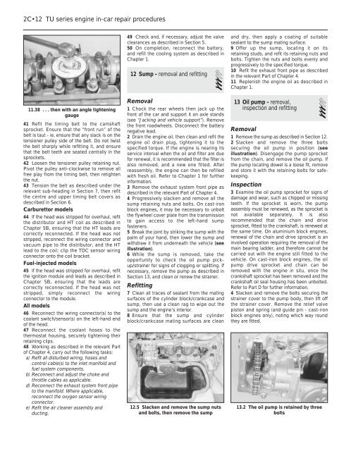
5 Break the joint by striking the sump with the<br />
palm of your hand, then lower the sump and<br />
withdraw it from underneath the vehicle (see<br />
illustration).<br />
6 While the sump is removed, take the<br />
opportunity to check the oil pump pickup/strainer<br />
for signs of clogging or splitting. If<br />
necessary, remove the pump as described in<br />
Section 13, and clean or renew the strainer.<br />
Refitting<br />
7 Clean all traces of sealant from the mating<br />
surfaces of the cylinder block/crankcase and<br />
sump, then use a clean rag to wipe out the<br />
sump and the engine’s interior.<br />
8 Ensure that the sump and cylinder<br />
block/crankcase mating surfaces are clean<br />
12.5 Slacken and remove the sump nuts<br />
and bolts, then remove the sump<br />
and dry, then apply a coating of suitable<br />
sealant to the sump mating surface.<br />
9 Offer up the sump, locating it on its<br />
retaining studs, and refit its retaining nuts and<br />
bolts. Tighten the nuts and bolts evenly and<br />
progressively to the specified torque.<br />
10 Refit the exhaust front pipe as described<br />
in the relevant Part of Chapter 4.<br />
11 Replenish the engine oil as described in<br />
Chapter 1.<br />
13 Oil pump - removal,<br />
inspection and refitting 3<br />
Removal<br />
1 Remove the sump as described in Section 12.<br />
2 Slacken and remove the three bolts<br />
securing the oil pump in position (see<br />
illustration). Disengage the pump sprocket<br />
from the chain, and remove the oil pump. If<br />
the pump locating dowel is a loose fit, remove<br />
and store it with the retaining bolts for safekeeping.<br />
Inspection<br />
3 Examine the oil pump sprocket for signs of<br />
damage and wear, such as chipped or missing<br />
teeth. If the sprocket is worn, the pump<br />
assembly must be renewed, as the sprocket is<br />
not available separately. It is also<br />
recommended that the chain and drive<br />
sprocket, fitted to the crankshaft, is renewed at<br />
the same time. On aluminium block engines,<br />
renewal of the chain and drive sprocket is an<br />
involved operation requiring the removal of the<br />
main bearing ladder, and therefore cannot be<br />
carried out with the engine still fitted to the<br />
vehicle. On cast-iron block engines, the oil<br />
pump drive sprocket and chain can be<br />
removed with the engine in situ, once the<br />
crankshaft sprocket has been removed and the<br />
crankshaft oil seal housing has been unbolted.<br />
Refer to Part D for further information.<br />
4 Slacken and remove the bolts securing the<br />
strainer cover to the pump body, then lift off<br />
the strainer cover. Remove the relief valve<br />
piston and spring (and guide pin - cast-iron<br />
block engines only), noting which way round<br />
they are fitted.<br />
13.2 The oil pump is retained by three<br />
bolts