1 2 3 4 5
1 2 3 4 5
1 2 3 4 5

You also want an ePaper? Increase the reach of your titles
YUMPU automatically turns print PDFs into web optimized ePapers that Google loves.
2C•4 TU series engine in-car repair procedures<br />
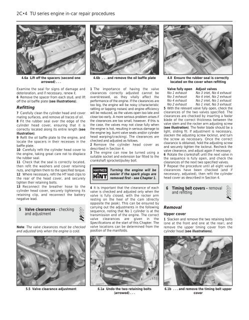
4.6a Lift off the spacers (second one<br />
arrowed) . . .<br />
4.6b . . . and remove the oil baffle plate 4.8 Ensure the rubber seal is correctly<br />
located on the cover when refitting<br />
Examine the seal for signs of damage and<br />
deterioration, and if necessary, renew it.<br />
6 Remove the spacer from each stud, and lift<br />
off the oil baffle plate (see illustrations).<br />
Refitting<br />
7 Carefully clean the cylinder head and cover<br />
mating surfaces, and remove all traces of oil.<br />
8 Fit the rubber seal over the edge of the<br />
cylinder head cover, ensuring that it is<br />
correctly located along its entire length (see<br />
illustration).<br />
9 Refit the oil baffle plate to the engine, and<br />
locate the spacers in their recesses in the<br />
baffle plate.<br />
10 Carefully refit the cylinder head cover to<br />
the engine, taking great care not to displace<br />
the rubber seal.<br />
11 Check that the seal is correctly located,<br />
then refit the washers and cover retaining<br />
nuts, and tighten them to the specified torque.<br />
12 Where necessary, refit the HT lead clips to<br />
the rear of the head cover, and securely<br />
tighten their retaining bolts.<br />
13 Reconnect the breather hose to the<br />
cylinder head cover, securely tightening its<br />
retaining clip, and reconnect the battery<br />
negative lead.<br />
5 Valve clearances - checking<br />
and adjustment<br />
2<br />
Note: The valve clearances must be checked<br />
and adjusted only when the engine is cold.<br />
1 The importance of having the valve<br />
clearances correctly adjusted cannot be<br />
overstressed, as they vitally affect the<br />
performance of the engine. If the clearances are<br />
too big, the engine will be noisy (characteristic<br />
rattling or tapping noises) and engine efficiency<br />
will be reduced, as the valves open too late and<br />
close too early. A more serious problem arises if<br />
the clearances are too small, however. If this is<br />
the case, the valves may not close fully when<br />
the engine is hot, resulting in serious damage to<br />
the engine (eg. burnt valve seats and/or cylinder<br />
head warping/cracking). The clearances are<br />
checked and adjusted as follows.<br />
2 Remove the cylinder head cover as<br />
described in Section 4.<br />
3 The engine can now be turned using a<br />
suitable socket and extension bar fitted to the<br />
crankshaft sprocket/pulley bolt.<br />
Turning the engine will be<br />
easier if the spark plugs are<br />
removed first - see Chapter 1.<br />
4 It is important that the clearance of each<br />
valve is checked and adjusted only when the<br />
valve is fully closed, with the rocker arm<br />
resting on the heel of the cam (directly<br />
opposite the peak). This can be ensured by<br />
carrying out the adjustments in the following<br />
sequence, noting that No 1 cylinder is at the<br />
transmission end of the engine. The correct<br />
valve clearances are given in the<br />
Specifications at the start of this Chapter. The<br />
valve locations can be determined from the<br />
position of the manifolds.<br />
Valve fully open Adjust valves<br />
No 1 exhaust No 3 inlet, No 4 exhaust<br />
No 3 exhaust No 4 inlet, No 2 exhaust<br />
No 4 exhaust No 2 inlet, No 1 exhaust<br />
No 2 exhaust No 1 inlet, No 3 exhaust<br />
5 With the relevant valve fully open, check the<br />
clearances of the two valves specified. The<br />
clearances are checked by inserting a feeler<br />
blade of the correct thickness between the<br />
valve stem and the rocker arm adjusting screw<br />
(see illustration). The feeler blade should be a<br />
light, sliding fit. If adjustment is necessary,<br />
slacken the adjusting screw locknut, and turn<br />
the screw as necessary. Once the correct<br />
clearance is obtained, hold the adjusting screw<br />
and securely tighten the locknut. Recheck the<br />
valve clearance, and adjust again if necessary.<br />
6 Rotate the crankshaft until the next valve in<br />
the sequence is fully open, and check the<br />
clearances of the next two specified valves.<br />
7 Repeat the procedure until all eight valve<br />
clearances have been checked (and if<br />
necessary, adjusted), then refit the cylinder<br />
head cover as described in Section 4.<br />
6 Timing belt covers - removal<br />
and refitting<br />
1<br />
Removal<br />
Upper cover<br />
1 Slacken and remove the two retaining bolts<br />
(one at the front and one at the rear), and<br />
remove the upper timing cover from the<br />
cylinder head (see illustrations).<br />
5.5 Valve clearance adjustment 6.1a Undo the two retaining bolts 6.1b . . . and remove the timing belt upper<br />
(arrowed) . . .<br />
cover