5 5- Communication 1 2 3 4 5 6 7 8 9 10 - Schneider Electric
5 5- Communication 1 2 3 4 5 6 7 8 9 10 - Schneider Electric
5 5- Communication 1 2 3 4 5 6 7 8 9 10 - Schneider Electric

You also want an ePaper? Increase the reach of your titles
YUMPU automatically turns print PDFs into web optimized ePapers that Google loves.
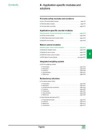
Contents<br />
5 - <strong>Communication</strong><br />
Selection guide: networks, buses and serial links page 5/2<br />
1<br />
Selection guide : Web servers and gateways page 5/8<br />
Ethernet network - Transparent Ready<br />
b Architectures page 5/12<br />
2<br />
3<br />
4<br />
5<br />
6<br />
7<br />
b Embedded Web servers<br />
v Presentation page 5/14<br />
v Standard Web services page 5/16<br />
v FactoryCast Web server page 5/18<br />
v FactoryCast HMI Web server page 5/20<br />
v SOAP/XML Web service page 5/26<br />
b Ethernet Modbus/TCP communication services<br />
v Presentation page 5/27<br />
v Standard Ethernet services page 5/28<br />
v I/O Scanning service page 5/30<br />
v FDR replacement service for faulty devices page 5/31<br />
v Global Data service page 5/32<br />
v NTP time synchronization service (Unity Pro) page 5/33<br />
v SMTP electronic mail notification service (Unity Pro) page 5/34<br />
v SNMP service protocol page 5/35<br />
v TCP Open optional service page 5/36<br />
b Performances page 5/38<br />
b Description, charactéristiques and references<br />
v Processors with integrated Ethernet port page 5/44<br />
v Ethernet Modbus/TCP modules page 5/45<br />
v EtherNet/IP module page 5/46<br />
b ConneXium, Ethernet wiring system<br />
v Infrastructure page 5/48<br />
v Connection components page 5/50<br />
v Hub and transceiver page 5/52<br />
v Unmanaged switches page 5/54<br />
v Managed switches page 5/57<br />
CANopen machines and installations bus<br />
8<br />
b Presentation and connectable devices page 5/62<br />
b CANopen PCMCIA card page 5/63<br />
b Wiring system page 5/65<br />
9<br />
AS-Interface sensor/actuator bus<br />
b AS-Interface master module page 5/68<br />
b Wiring system page 5/72<br />
b Phaseo regulated power supplies for AS-Interface . . see page 8/20<br />
<strong>10</strong><br />
5/0
X-Way bus and network<br />
b <strong>Communication</strong> architecture page 5/74<br />
b Fipio bus manager function page 5/76<br />
1<br />
b Fipio bus Agent function page 5/79<br />
b Fipway network page 5/82<br />
b Fipio/Fipway optic transceiver page 5/84<br />
b Fipio/Fipway wiring system page 5/86<br />
2<br />
Network and fieldbus<br />
b Modbus Plus network page 5/90<br />
b Profibus DP fieldbus page 5/94<br />
3<br />
b InterBus fieldbus page 5/96<br />
Serial links<br />
b Modbus serial link page 5/<strong>10</strong>0<br />
b Uni-Telway serial link page 5/<strong>10</strong>4<br />
b Asynchronous serial links page 5/<strong>10</strong>8<br />
b Connecting cables for PCMCIA cards and TER/AUX ports page 5/1<strong>10</strong><br />
4<br />
5<br />
6<br />
7<br />
8<br />
9<br />
<strong>10</strong><br />
5/1
Selection guide<br />
Modicon Premium<br />
automation platform 0<br />
Ethernet CPUs and modules<br />
Transparent Ready<br />
1<br />
Applications<br />
Processors with built-in Ethernet Modbus/TCP port<br />
2<br />
3<br />
Type of network<br />
Ethernet Modbus/TCP<br />
Structure Physical interface <strong>10</strong>BASE-T/<strong>10</strong>0BASE-TX (RJ45)<br />
Method of access<br />
CSMA-CD<br />
Data rate<br />
<strong>10</strong>/<strong>10</strong>0 Mbit/s<br />
4<br />
Medium<br />
CAT 5E double twisted pair cable<br />
Optical fiber, via Ethernet ConneXium wiring system<br />
5<br />
6<br />
Configuration Maximal number of devices Maximum of 64 stations per network,<br />
maximum of 128 stations per network with TSX P57 5634M/6634M processors<br />
Maximum length<br />
<strong>10</strong>0 m (copper cable), 4,000 m (multimode optical fiber), 32,200 m (single mode optical fiber)<br />
Number of networks/station 1 integrated Ethernet port 3 (1) 4 (1)<br />
Other built-in port – Fipio bus manager<br />
function<br />
– Fipio bus manager<br />
function<br />
Basic services Services Ethernet Uni-TE and Modbus/TCP message handling<br />
Services X-Way<br />
Inter-network X-Way routing, X-Way/Uni-Telway routing, module diagnostics<br />
Ethway –<br />
Transparent Ready class<br />
B30<br />
7<br />
Embedded Web<br />
serverservices<br />
Basic services<br />
“Rack Viewer” PLC diagnostics<br />
“Data Editor” access to PLC variables and data<br />
FactoryCast services –<br />
Factory Cast HMI services –<br />
Transparent Ready communication services<br />
I/O Scanning (64 stations, 128 stations with TSX P57 5634M/6634M processors), Global data<br />
8<br />
9<br />
Type of processor –<br />
–<br />
SMTP, E-mail notification (via Unity Pro function blocks)<br />
SNMP, network management, bandwidth management<br />
–<br />
FDR server for automatic assignment of IP address and network parameters<br />
–<br />
Module format<br />
Double format processor<br />
<strong>10</strong><br />
Type of module<br />
TSX P57 1634M<br />
TSX P57 2623M<br />
TSX P57 2634M<br />
TSX P57 2823M<br />
TSX P57 3623AM<br />
TSX P57 3634M<br />
TSX P57 4823M<br />
TSX P57 4634M<br />
TSX P57 5634M<br />
TSX P57 6634M<br />
Page 5/44<br />
(1) Including the integrated Ethernet port.<br />
5/2
0<br />
Ethernet Modbus/TCP modules<br />
EtherNet/IP module<br />
1<br />
2<br />
Ethernet Modbus/TCP (continued)<br />
<strong>10</strong>BASE5 (AUI), <strong>10</strong>BASE-T <strong>10</strong>BASE-T, <strong>10</strong>0BASE-TX (RJ45)<br />
CSMA-CD<br />
<strong>10</strong> Mbit/s <strong>10</strong>/<strong>10</strong>0 Mbit/s<br />
EtherNet/IP<br />
3<br />
Triaxial cable or double<br />
twisted pair, Optical fiber, via<br />
ConneXium wiring system<br />
CAT 5E double twisted pair cable<br />
Optical fiber, via Ethernet ConneXium wiring system<br />
4<br />
Maximum of 64 stations per network<br />
<strong>10</strong>0 m (copper cable), 4,000 m (multimode optical fiber), 32,200 m (single mode optical fiber)<br />
1 to 4 depending on processor or slot PLC used<br />
–<br />
5<br />
Uni-TEand Modbus/TCP message handling<br />
EtherNet/IP<br />
Inter-network X-Way routing, X-Way/Uni-Telway routing, module diagnostics –<br />
Uni-Te message handlig ,<br />
common words, application<br />
to application<br />
– –<br />
C<strong>10</strong> B30 C30 D<strong>10</strong> No Web server<br />
“Rack Viewer” PLC diagnostics<br />
“Data Editor” access to PLC variables and data<br />
“Alarms viewer”<br />
“Graphic Data Editor”<br />
Display of user Web pages<br />
(14 Mb available)<br />
– “Alarms viewer” alarm display<br />
“Graphic Data Editor” graphic object editor<br />
Display of user Web pages (8 Mb available)<br />
– FactoryCast HMI services (2) –<br />
–<br />
–<br />
6<br />
7<br />
– I/O Scanning (64 stations), Global Data – CIP Implicit messaging<br />
CIP Explicit messaging<br />
– NTP time synchronisation – –<br />
– SMTP, E-mail notification (via Unity Pro function blocks) SMTP, E-mail notification –<br />
(active Web server)<br />
SNMP network management SNMP, network management, bandwidth management SNMP network management SNMP network management<br />
– SOAP XML Web server SOAP XML Web client/server –<br />
– FDR server for automatic assignment of IP address and –<br />
network parameters)<br />
TCP Open – TCP Open –<br />
All types of Premium processors TSX P57 1p/57 2p/57 3p/57 4p/57 5p /57 6p<br />
Atrium slot PLCs TSX PCI 57 204M/354M –<br />
8<br />
9<br />
Standard format module<br />
TSX ETY 1<strong>10</strong> WS TSX ETY 4<strong>10</strong>3 TSX ETY 5<strong>10</strong>3 TSX WMY <strong>10</strong>0 TSX ETC <strong>10</strong>0<br />
<strong>10</strong><br />
5/45 5/45 5/47<br />
(2) FactoryCast HMI services : HMI database, E.mail with automatic sending on events, interpreted math and logic functions, connection to relational databases<br />
and simulator tool.<br />
5/3
Selection guide (continued)<br />
Modicon Premium<br />
automation platform 0<br />
Network and bus modules<br />
1<br />
Applications<br />
Local area network conforming to<br />
Modbus Plus standard<br />
Local area network conforming to Fip<br />
2<br />
3<br />
Type of network or bus Modbus Plus Fipway<br />
Structure Physical interface Modbus Plus standard Fip standard<br />
4<br />
Method of access Rotating token Bus managed by bus arbitrator<br />
Data rate 1 Mbit/s 1 Mbit/s<br />
Medium Twisted pair Twisted shielded pair<br />
Fibre optic via transceivers or repeaters<br />
5<br />
Configuration Maximal number of devices 32 per segment<br />
64 on all segments<br />
Maximal length<br />
450 m per segment<br />
1800 m with 3 repeaters<br />
32 per segment<br />
128 on all segments<br />
<strong>10</strong>00 m per segment<br />
5000 m maxi with repeaters<br />
6<br />
Number of links/station 1 max 1 to 4 depending on the model of processeur<br />
Services Message handling - Write/read varaibles<br />
- Global database<br />
- Peer Cop service<br />
- Uni-TE<br />
- COM/shared table<br />
- Application-to-application<br />
- Telegram<br />
7<br />
Type of processor<br />
Nature of module<br />
All type of Premium processors and Atrium slot PLCs<br />
PCMCIA type III card on processor or<br />
slot PLC<br />
PCMCIA type III card on<br />
processors (1) or slot PLCs and on<br />
TSX SCY 21601 module<br />
8<br />
Type of module TSX MBP <strong>10</strong>0 TSX FPP 20<br />
Pages 5/93 5/83<br />
(1) Except on TSX P57 4634M/5634M/6634M processors with integrated Ethernet port.<br />
9<br />
<strong>10</strong><br />
5/4
0<br />
CAN fieldbus Sensor/actuator bus conforming to AS-i standard Modbus open industrial bus<br />
1<br />
1<br />
2<br />
Bus CANopen V4.02 AS-Interface Modbus<br />
ISO 11898 V2 AS-Interface standard RS 232<br />
RS 485 isolated<br />
20 mA CL<br />
CSMA/CA, multi-master Master/slave Master/slave<br />
20 Kbit/s1 Mbit/s according to distance 167 Kbit/s 192 Kbit/s max<br />
Twisted shielded pair 2-wire AS-Interface cable Twisted shielded pair<br />
RS 485 isolated<br />
3<br />
4<br />
127 slaves 31 + 31 discrete, analog or security devices 32 devices max<br />
48 slave addresses<br />
max<br />
From 20 m (1 Mbit/s)…2500 m (20 Kbit/s)<br />
<strong>10</strong>0 m<br />
200 m with repeaters<br />
15 m in RS 232<br />
<strong>10</strong>00 m in RS 485<br />
1300 m in 20 mA CL or<br />
intégrated link<br />
1 max 2 to 8 depending on the model of processor See characteristics page 5/<strong>10</strong>1<br />
- Implicit PDO exchange<br />
- Explicit SDO exchange or CAN function block<br />
- Explicit PDU CAN exchange<br />
Transparency of exchanges with sensor/actuator<br />
devices<br />
32 devices max<br />
247 slave addresses<br />
max<br />
1300 m<br />
Modbus master/slace RTU or ASCII<br />
13 Modbus functions (read/write bits and words,<br />
diagnostic…)<br />
5<br />
6<br />
All type of Premium processors (except<br />
TSX P57 153) and Atrium slot PLCs<br />
PCMCIA type III card on Premium processor or on<br />
Atrium slot PLC<br />
All type of Premium processors and Atrium slot PLCs<br />
Standard format module<br />
PCMCIA type III card<br />
inserted on (2)<br />
Standard format<br />
module<br />
7<br />
TSX CPP 1<strong>10</strong> TSX SAY <strong>10</strong>00 TSX SCP 11p (3) TSX SCY 11601<br />
built-in link<br />
1<br />
TSX SCY 21601<br />
5/63 5/69 5/<strong>10</strong>2<br />
(2) Premium processor/Atrium slot PLC and TSX SCY 21601 communication module.<br />
(3) At the end of reference, replace p by 1: RS 232, by 2: 20 mA CL or by 4: isolated RS 485.<br />
8<br />
9<br />
<strong>10</strong><br />
5/5
Selection guide (continued)<br />
Modicon Premium<br />
automation platform 0<br />
Network, bus and serial link modules<br />
1<br />
Applications Local area network conforming to Fip Uni-Telway multicomponent industrial bus<br />
2<br />
2<br />
2<br />
1<br />
3<br />
Type of network or bus Fipio (Agent) Fipio (gestionnaire<br />
de bus)<br />
Bus Uni-Telway<br />
4<br />
Structure Physical interface Fip standard RS 485 non-isolated RS 485 isolated<br />
Method of access Bus managed by bus arbitrator Master/slave<br />
Data rate 1 Mbit/s 19,2 Kbit/s max<br />
Medium<br />
Twisted shielded pair<br />
Fibre optic via transceivers or repeaters<br />
Twisted shielded pair<br />
5<br />
Configuration Maximal number of devices 32 per segment,<br />
128 on all segments (limited to 64 with<br />
TSX P57 0p/1p processor )<br />
Maximal length<br />
From <strong>10</strong>00 m to 15 000 m (depending on the<br />
medium use) with repeaters<br />
5 (excluding<br />
programming<br />
terminal)<br />
<strong>10</strong> m <strong>10</strong>00 m<br />
28, (96 slaves<br />
addresses max)<br />
Number of links/station 1 max 1 max See characteristics<br />
page 5/<strong>10</strong>4<br />
6<br />
Services Message handling - Uni-TE<br />
- Periodic data exchange<br />
- Application-to-application<br />
- Transparent exchange of remote I/O<br />
-<br />
-<br />
-<br />
Uni-TE Client/Server 240 bytes (128 bytes<br />
on terminal port)<br />
Application-to-application 240 bytes<br />
(128 bytes on terminal port)<br />
Transparency of all devices on X-Way<br />
architecture via the master<br />
7<br />
Type of processors<br />
Nature of module<br />
All type of Premium<br />
processors and<br />
Atrium slot PLCs<br />
PCMCIA type III card<br />
on processor or<br />
slot PLC<br />
TSX P57 p53M/p54M<br />
TSX P57 p823M<br />
TSX PCI 57 354M<br />
Built-in on the<br />
processor or<br />
slot PLC<br />
All type of Premium processors and Atrium<br />
slot PLCs<br />
Uni-Telway built-in<br />
link<br />
Standard format<br />
module<br />
8<br />
Type of module TSX FPP <strong>10</strong> 2<br />
Built-in link<br />
on processor<br />
1 AUX terminal<br />
port<br />
2<br />
Pages 5/81 5/79 5/<strong>10</strong>7<br />
TSX SCY<br />
21601<br />
9<br />
<strong>10</strong><br />
5/6
0<br />
Uni-Telway multicomponent industrial bus InterBus industrial fieldbus Profibus industrial fieldbus<br />
1<br />
2<br />
Bus Uni-Telway (continued) InterBus Profibus DP<br />
3<br />
RS 232, RS 485 isolated and 20 mA CL RS 485 isolated RS 485<br />
Master/slave Master/slave generation 4 Master<br />
19,2 Kbit/s max 500 Kbit/s 9,6 Kbit/s12 Mbit/s according to lenght of bus<br />
Twisted shielded pair<br />
Twisted shielded pair,<br />
Fiber optic, infra-red <br />
Twisted shielded pair,<br />
Fiber optic or infra-red<br />
4<br />
2 in RS 232,<br />
28 in RS 485,<br />
16 in 20 mA CL<br />
15 m in RS 232,<br />
<strong>10</strong>00 m in RS 485 isolated<br />
1300 m in 20 mA CL<br />
See characteristics page 5/<strong>10</strong>4<br />
512 slaves max with 254 bus terminal blocks max 126 slaves<br />
400 m max (inter-station bus) 1200 m (9,6 Kbit/s), 4800 m with 3 repeaters<br />
<strong>10</strong>0 m (12 Mbit/s), 400 m with 3 repeaters<br />
1 ou 2 depending on the type of Premium processors or Atrium slot PLCs<br />
5<br />
-<br />
-<br />
-<br />
Uni-TE Client/Server 240 bytes (128 bytes on<br />
terminal port)<br />
Application-to-application 240 bytes (128 bytes<br />
on terminal port)<br />
Transparency of all devices on X-Way<br />
architecture via the master<br />
- Data process implicit exchange<br />
- Pre-processing<br />
- Logical addressing<br />
- Segmentation<br />
- Read/write access for DP slave I/O data<br />
- Data transfer for slave diagnostics<br />
- Parametering and monitoring requests<br />
- Inter-master dialog not supported<br />
6<br />
All type of Premium processors and Atrium slot<br />
PLCs<br />
PCMCIA type III card on processor or slot PLC<br />
and on TSX SCY 21601 module<br />
All type of Premium processors(except TSX 57 0p/1p) and Atrium slot PLCs<br />
Standard format<br />
module<br />
PC card on ISA bus<br />
Standard format module<br />
7<br />
TSX SCP 11p<br />
(1)<br />
TSX IBY <strong>10</strong>0 TSX IBX <strong>10</strong>0 TSX PBY <strong>10</strong>0<br />
5/99 5/95<br />
(1) At the end of reference, replace p by 1: RS 232, by 2: 20 mA CL or by 4: isolated RS 485.<br />
8<br />
9<br />
<strong>10</strong><br />
5/7
Selection guide<br />
Modicon Premium<br />
automation platform<br />
Web servers and gateways<br />
Applications<br />
Web Server modules for PLCs<br />
1<br />
FactoryCast<br />
2<br />
3<br />
Target products Type TSX Micro PLCs Modicon M340 PLCs<br />
4<br />
Network/Remote<br />
access services<br />
Remote access<br />
Gateway function –<br />
Intranet or via external RAS/modem<br />
Remote programming, downloading via FTP, access to Web server via Internet browser<br />
Serial protocols –<br />
Ethernet protocols Modbus/TCP, Uni-TE Modbus/TCP<br />
5<br />
TCP/IP protocols<br />
Security<br />
BootP/DHCP, DNS, SNMP agent, SMTP client, NTP client, FTP<br />
Protection by IP address filtering and passwords<br />
Web server Characteristics HTTP and FTP server, 8 Mb memory available for user, hosting of user Web pages and<br />
documents (Doc, Pdf, Excel)<br />
6<br />
Predefined services Configuration Via Web Designer software or predefined Web pages<br />
Diagnostics<br />
System, rack and PLC I/O diagnostics via predefined Web pages<br />
Monitoring of variables<br />
Monitoring of devices and application via animation tables (read/write variables)<br />
Alarm management<br />
Monitoring of PLC and application alarms via predefined Web pages<br />
7<br />
Customizable<br />
services<br />
Advanced services<br />
and HMI<br />
Graphic views<br />
Graphic monitoring via animated views (integrated graphic editor)<br />
Unity Pro operator screen –<br />
User Web pages<br />
Surveillance graphique par pages Web animées créées par l’utilisateur<br />
Calculation scripts –<br />
E-mail service<br />
Alarm notification by e-mail<br />
Data logging –<br />
8<br />
Database connection –<br />
Report service –<br />
Recipe service –<br />
9<br />
Application development software<br />
Web Designer<br />
Supplied with each module<br />
<strong>10</strong><br />
References TSX ETZ 5<strong>10</strong> BMX NOE 01<strong>10</strong><br />
Pages or catalogues TSX Micro automation platform Modicon M340 automation platform<br />
5/8
1<br />
Web Server modules for PLCs<br />
FactoryCast<br />
FactoryCast HMI<br />
1<br />
2<br />
Modicon Premium PLCs Modicon Quantum PLCs Modicon Premium PLCs Modicon Quantum PLCs<br />
3<br />
Intranet or via external RAS/modem<br />
Intranet or via external RAS/modem<br />
Remote programming, downloading via FTP, access to Web server via Internet<br />
browser<br />
– –<br />
Remote programming, downloading via FTP, access to Web server via Internet<br />
browser<br />
4<br />
– –<br />
Modbus/TCP, Uni-TE Modbus/TCP Modbus/TCP, Uni-TE Modbus/TCP<br />
BootP/DHCP, DNS, SNMP agent, SMTP client, NTP client, FTP<br />
Protection by IP address filtering and passwords<br />
HTTP and FTP server, 8 Mb memory available for user, hosting of user Web<br />
pages and documents (Doc, Pdf, Excel)<br />
BootP/DHCP, DNS, SNMP agent, SMTP client, NTP client, FTP<br />
Protection by IP address filtering and passwords<br />
HTTP and FTP server, 8 Mb memory available for user, hosting of user Web<br />
pages and documents (Doc, Pdf, Excel)<br />
5<br />
Via Web Designer software or predefined Web pages<br />
System, rack and PLC I/O diagnostics via predefined Web pages<br />
Monitoring of devices and application via animation tables (read/write<br />
variables)<br />
Monitoring of PLC and application alarms via predefined Web pages<br />
Via Web Designer software or predefined Web pages<br />
System, rack and PLC I/O diagnostics via predefined Web pages<br />
Monitoring of devices and application via animation tables (read/write<br />
variables)<br />
Monitoring of PLC and application alarms via predefined Web pages<br />
6<br />
Graphic monitoring via animated views (integrated graphic editor)<br />
Graphic monitoring via animated views (integrated graphic editor)<br />
– Display in the form of Web pages<br />
Graphic monitoring via animated Web pages created by the user<br />
Graphic monitoring via animated Web pages created by the user<br />
– Arithmetic and logical scripts<br />
Alarm notification by e-mail<br />
Alarm notification by e-mail<br />
– Data recorded in the module with time stamping<br />
– Direct recording in an SQL, Oracle, MySQL server<br />
– Dynamic HTML report management<br />
– Management of “Recipe” data (storage and review locally or on remote<br />
database)<br />
Web Designer<br />
Supplied with each module<br />
7<br />
8<br />
9<br />
TSX ETY 5<strong>10</strong>3 140 NOE 77111 TSX WMY<strong>10</strong>0 140 NWM <strong>10</strong>000<br />
<strong>10</strong><br />
5/45 Quantum automation platform 5/45 Quantum automation platform<br />
5/9
Selection guide<br />
Modicon Premium<br />
automation platform<br />
Web servers and gateways<br />
Applications<br />
Standalone Gateway, Web Server for Remote Access<br />
1<br />
FactoryCast Gateway ETG <strong>10</strong>p0<br />
2<br />
3<br />
Target products Type All equipment supporting Modbus All equipment supporting Uni-Telway<br />
Network/Remote<br />
access services<br />
Remote access<br />
Intranet or via external Modem, integrated RAS function<br />
Remote programming, downloading via FTP, access to Web server via Internet browser<br />
4<br />
Gateway function<br />
Ethernet to Modbus serial<br />
Modem to Modbus serial and Ethernet<br />
Ethernet to Uni-Telway serial<br />
Modem to Uni-Telway and Ethernet<br />
Serial protocols Modbus master Uni-Telway slave<br />
Ethernet protocols Modbus/TCP Modbus/TCP, Uni-TE (Premium, Micro)<br />
5<br />
TCP/IP protocols<br />
Security<br />
BootP/DHCP, SNMP agent, SMTP client, NTP client, FTP<br />
Protection by IP address filtering and password<br />
Web server Characteristics HTTP and FTP server, 8 Mb memory available for user, hosting of user Web pages and<br />
documents (Doc, Pdf, Excel)<br />
6<br />
Predefined services Configuration Via Web Designer software or predefined Web pages<br />
Diagnostics<br />
Diagnostics of serial devices via predefined Web pages<br />
Monitoring of variables<br />
Monitoring of devices and application via animation tables (read/write variables)<br />
Alarm management –<br />
7<br />
Customizable<br />
services<br />
Advanced services<br />
and HMI<br />
Graphic views<br />
Graphic monitoring via animated views (integrated graphic editor)<br />
Unity Pro operator screen –<br />
User Web pages<br />
Graphic monitoring via animated Web pages created by the user<br />
Calculation scripts –<br />
E-mail service<br />
Alarm notification by e-mail<br />
Data logging –<br />
Database connection –<br />
8<br />
Report service –<br />
Recipe service –<br />
Application development software<br />
Web Designer<br />
Supplied with each module<br />
9<br />
<strong>10</strong><br />
References TSX ETG<strong>10</strong>00 TSX ETG<strong>10</strong><strong>10</strong><br />
Web site<br />
schneider-automationcom<br />
5/<strong>10</strong>
1<br />
Standalone Gateway, Web Server for Remote Access<br />
FactoryCast HMI Gateway ETG30pp<br />
1<br />
2<br />
All Modicon PLCs and third-party equipment supporting Modbus<br />
3<br />
Intranet or Modem<br />
External modem, integrated RAS<br />
Intranet or Modem<br />
Integrated PSTN modem and RAS<br />
Remote programming, downloading via FTP, access to Web server via Internet browser<br />
Ethernet to Uni-Telway serial<br />
Modem to serial Modbus and Ethernet<br />
Modbus master<br />
Modbus/TCP<br />
Intranet or Modem<br />
Integrated GSM modem and RAS<br />
4<br />
DHCP, DNS, SNMP agent, SMTP client, NTP client, FTP<br />
Protection by IP address filtering and password<br />
HTTP and FTP server, 32 Mb memory available for user Web pages, memory extension using Compact Flash cards 1 Gb max, hosting of user Web pages and<br />
documents (Doc, Pdf, Excel)<br />
5<br />
Via Web Designer software or predefined Web pages<br />
Network diagnostics, diagnostics of serial and Ethernet devices via predefined Web pages<br />
Monitoring of devices and application via animation tables (read/write variables)<br />
–<br />
6<br />
Graphic monitoring via animated views (integrated graphic editor)<br />
–<br />
Graphic monitoring via animated Web pages created by the user<br />
Arithmetic and logical scripts<br />
Alarm notification by e-mail/SMS<br />
Data logging in the module with time stamping (CSV files)<br />
7<br />
Direct recording in an SQL, Oracle, MySQL server<br />
Dynamic HTML report management<br />
Management of “Recipe” data (storage and review locally or on remote database)<br />
8<br />
Web Designer<br />
Supplied with each module<br />
9<br />
TSX ETG3000 TSX ETG30<strong>10</strong> (PSTN modem) TSX ETG3021 (GSM 900/1800 MHz band)<br />
TSX ETG3022 (GSM 850/1900 MHz band)<br />
<strong>10</strong><br />
schneider-automationcom<br />
5/11
INPUT<br />
A<br />
OUTPUT<br />
B<br />
OUTPUT<br />
B<br />
+ –<br />
A<br />
Architecture<br />
Modicon Premium<br />
automation platform 0<br />
Ethernet Modbus/TCP network<br />
Logical Ethernet communication architecture<br />
1<br />
Company<br />
Intranet<br />
Internet<br />
Site 3<br />
Site 2<br />
2<br />
Enterprise<br />
MES<br />
ERP<br />
Unix Windows Linux<br />
Site 1<br />
3<br />
Factory<br />
HMI + SCADA<br />
Ethernet Modbus/TCP<br />
4<br />
Workshop<br />
Industrial PC<br />
Quantum<br />
Quantum<br />
Quantum<br />
5<br />
Premium<br />
Premium<br />
6<br />
Dialog terminal<br />
Modicon M340<br />
7<br />
PLC<br />
Collaborative<br />
Automation<br />
Partner Program<br />
Momentum M1E<br />
Robot<br />
Distribued I/O<br />
8<br />
Gateway<br />
Servo drive<br />
INPUT<br />
+ –<br />
Advantys STB I/O<br />
9<br />
Workshop 1<br />
MES: Manufacturing Execution System (production management system)<br />
ERP: Enterprise Resource Planning (integrated management software packages)<br />
HMI/SCADA: Human/Machine Interface/Supervision Control And Data Acquisition<br />
Gateway: Bridge to sensor/actuator bus, to installed base network, field bus, etc.<br />
Workshop 2<br />
<strong>10</strong><br />
5/12
INPUT<br />
A<br />
OUTPUT<br />
B<br />
OUTPUT<br />
B<br />
+ –<br />
A<br />
Architecture (continued)<br />
Modicon Premium<br />
automation platform 0<br />
Ethernet Modbus/TCP network<br />
Physical Ethernet communication architecture<br />
Router<br />
Router<br />
WAN<br />
Provider<br />
Specialized link<br />
Frame Relay<br />
ATM<br />
Router<br />
Internet<br />
Provider<br />
Firewall<br />
RAS<br />
Public telecommunications<br />
network, ADSL<br />
Site 3<br />
Site 2<br />
Site 1<br />
1<br />
2<br />
(Max. 50 switches)<br />
Switches (VLAN)<br />
or routers<br />
Switch<br />
3<br />
Switch<br />
Redundant optical ring<br />
Switch<br />
ERP<br />
<strong>10</strong>0BASE-FX<br />
Full Duplex<br />
Switch<br />
Half Duplex<br />
Max.<br />
3,<strong>10</strong>0 m<br />
MES<br />
4<br />
Collision domain 2<br />
Premium<br />
Quantum<br />
Switch<br />
Max.<br />
<strong>10</strong>0 m<br />
Max.<br />
<strong>10</strong>0 m<br />
Max.<br />
<strong>10</strong>0 m<br />
Hub<br />
Fiber optics<br />
Quantum<br />
5<br />
<strong>10</strong>0BASE-TX<br />
Momentum<br />
M1E<br />
Collaborative<br />
Automation<br />
Partner Program<br />
Third-party device<br />
Hub<br />
Hub<br />
Transceiver<br />
6<br />
TSX Micro<br />
Gateway<br />
Max.<br />
2<strong>10</strong> m<br />
Max.<br />
<strong>10</strong>0 m<br />
Collision domain 1<br />
Magelis iPC<br />
Vijeo Designer<br />
INPUT<br />
+ –<br />
Advantys STB<br />
Hub<br />
Robot<br />
7<br />
AS-Interface bus<br />
Max.<br />
<strong>10</strong>0 m<br />
Altivar 71<br />
Modicon M340<br />
8<br />
Collision domain 3 (1)<br />
(1) In general, several collision domains should be defined in order to increase the architecture surface and improve performance. See pages 9/12 to 9/17.<br />
9<br />
<strong>10</strong><br />
5/13
Overview<br />
Modicon Premium<br />
automation platform<br />
Transparent Ready, system approach<br />
FactoryCast Web servers and gateways<br />
1<br />
Active Web server<br />
Class D (1)<br />
Local data or<br />
database logging<br />
E-mail/SMS notification<br />
FactoryCast Web server offer<br />
<strong>Schneider</strong> <strong>Electric</strong> offers a wide range of Transparent Ready products:<br />
controllers and PLCs, industrial PCs, HMI devices (2), variable speed drives,<br />
distributed I/O modules, gateways, Web servers, switches, SCADA software,<br />
inductive identification systems, etc.<br />
HMI functions<br />
These products provide different levels of Web services and communication services<br />
on Ethernet, according to user requirements<br />
2<br />
3<br />
4<br />
5<br />
6<br />
Configurable Web server<br />
Class C (1)<br />
Standard Web server<br />
Class B (1)<br />
User Web pages<br />
Display of graphic data<br />
Application diagnostics<br />
Reading/writing variables<br />
Product diagnostics<br />
Product configuration<br />
Among these Transparent Ready products, FactoryCast defines a range of modules<br />
and gateways with configurable Web server combining:<br />
b Real-time communication functions based on Ethernet Modbus/TCP<br />
b Predefined Web pages for advanced installation diagnostics<br />
b And the capacity to host dynamic user-defined Web pages or any document (.doc,<br />
pdf, etc) designed to assist maintenance<br />
Presentation of the Web server modules and gateways<br />
In the Transparent Ready approach, Ethernet modules and Web gateways integrate<br />
Ethernet services (Modbus/TCP messaging, SNMP network management functions,<br />
etc) They also offer, depending on the product, the following Web functions:<br />
b Standard Web services (predefined)<br />
b FactoryCast configurable Web services<br />
b FactoryCast HMI active Web services<br />
There are two ranges of configurable Web server:<br />
b FactoryCast Web modules for PLCs, which are embedded in the TSX Micro,<br />
Premium, Quantum and Modicon M340 automation platforms These modules<br />
provide transparent access to system and application diagnostic information in real<br />
time using Web technologies<br />
b FactoryCast Web Gateway modules, with all the network interfaces in one stand<br />
alone unit:<br />
v A modem (depending on the version)<br />
v An RAS/Router function<br />
v A customizable Web server<br />
v HMI functions (depending on the version)<br />
FactoryCast Gateways are a cost-effective response to requirements for remote<br />
access to customized remote diagnostics, maintenance, monitoring and control<br />
services using a simple Internet browser as well as to requirements to integrate<br />
serial installations (Modbus RTU or Uni-Telway) in an existing Ethernet Modbus/TCP<br />
infrastructure<br />
7<br />
Presentation of the Web services<br />
Standard Web services<br />
Standard Web services are integrated in the following <strong>Schneider</strong> <strong>Electric</strong> Ethernet<br />
products: automation platform processors and Ethernet modules, distributed I/O<br />
modules, variable speed drives and Ethernet gateways See page 5/15<br />
8<br />
Using a simple Internet browser, the standard Web server provides the following<br />
“ready-to-use” functions:<br />
b Product configuration<br />
b Remote diagnostics and maintenance of products<br />
b Display and adjustment of products (read/write variables, status)<br />
9<br />
The embedded Web server is a real-time data server All the data can be presented<br />
in the form of standard Web pages in HTML format and can therefore be accessed<br />
using any Web browser that supports the embedded Java code The standard<br />
functions provided by the Web server are supplied "ready-to-use" and therefore do<br />
not require any programming of either the PLC or the client PC device supporting a<br />
Web browser<br />
<strong>10</strong><br />
(1) In order to simplify choice and ensure their interoperability within a system, each<br />
Transparent Ready product is identified by the class of services it provides. Letter A, B, C or D<br />
(level of service for the Web server) followed by <strong>10</strong>, 20 or 30 (level of service for Ethernet<br />
communication).<br />
(2) HMI = Human Machine Interface.<br />
5/14
Presentation (continued),<br />
product selection<br />
Modicon Premium<br />
automation platform<br />
Transparent Ready, system approach<br />
FactoryCast Web servers and gateways<br />
Presentation of the Web services (continued)<br />
FactoryCast configurable Web services<br />
The configurable Web services are integrated in the following <strong>Schneider</strong> <strong>Electric</strong><br />
Ethernet products: FactoryCast PLC modules (TSX Micro, Premium and Quantum)<br />
and FactoryCast Gateway modules<br />
In addition to the standard Web services, the configurable Web servers offer the<br />
following functions:<br />
b Graphic application diagnostics (customized graphic views created by the user)<br />
b Graphic monitoring via animated Web pages created by the user and stored in the<br />
Web server module<br />
b And depending on the products:<br />
b Management of PLC system and application alarms with partial or total<br />
acknowledgement (ready-to-use Alarm Viewer function pages)<br />
b Open data server interface SOAP/XML protocol, WSDL interface (1)<br />
FactoryCast Web servers can also be used to customize the supervision, diagnostics or<br />
maintenance interface via user-defined Web pages or any other document (doc, pdf,<br />
etc) hosted in the module<br />
FactoryCast HMI active Web services<br />
The active Web services are integrated in the Premium and Quantum FactoryCast HMI<br />
PLC modules<br />
In addition to the FactoryCast Web services, the FactoryCast HMI modules provide HMI<br />
functions, which are executed in the module itself:<br />
Real-time HMI database management, independent of the PLC processor<br />
Arithmetic and logical calculations based on HMI data<br />
Direct connectivity with relational databases (traceability)<br />
Data Logging: recording of data in the module<br />
Display of Unity Pro graphic runtime screens in the form of Web pages<br />
Recipe management (read/write)<br />
Alarm and report notification by e-mail<br />
Active page server, dynamic generation of animated HTML pages<br />
Dynamic generation of HTML reports<br />
Open data server interface SOAP/XML WSDL interface protocol (1)<br />
b<br />
FactoryCast HMI is defined as an active Web server used to execute HMI functions<br />
without any effect on the PLC application program and therefore on its scan time<br />
(1) Standard protocol providing interoperability with computer management applications<br />
(see pages 5/26).<br />
Web server products<br />
Product Reference Embedded Web server<br />
Standard, class B20 Configurable, class C20/C30 Active, class D<strong>10</strong> (2)<br />
Modicon Quantum<br />
platform<br />
Modicon Premium<br />
platform<br />
Processors 140 CPU 651 50/60 –<br />
Modules 140 NOE 771 01 –<br />
140 NOE 771 11 FactoryCast<br />
140 NWM <strong>10</strong>0 00 FactoryCast FactoryCast HMI<br />
Processors TSX P57 2p23 M –<br />
TSX P57 3623 M –<br />
TSX P57 4823 M –<br />
TSX P57 1634 M –<br />
TSX P57 p634 M –<br />
Modules TSX ETY 4<strong>10</strong>3 –<br />
TSX ETY 1<strong>10</strong>WS<br />
FactoryCast<br />
TSX ETY 5<strong>10</strong>3<br />
FactoryCast<br />
TSX WMY <strong>10</strong>0 FactoryCast FactoryCast HMI<br />
Modicon M340 platform Module BMX NOE 01<strong>10</strong> FactoryCast<br />
Modicon TSX Micro<br />
platform<br />
Modules TSX ETZ 4<strong>10</strong> –<br />
TSX ETZ 5<strong>10</strong><br />
b<br />
b<br />
b<br />
b<br />
b<br />
b<br />
b<br />
b<br />
b<br />
FactoryCast<br />
Inductel identification station XGK S1715503 –<br />
FactoryCast Web Gateway TSX ETG <strong>10</strong>p0 FactoryCast<br />
FactoryCast HMI Web Gateway TSX ETG 30pp FactoryCast FactoryCast HMI<br />
(2) Class D20 for TSX ETG 30pp<br />
1<br />
2<br />
3<br />
4<br />
5<br />
6<br />
7<br />
8<br />
9<br />
<strong>10</strong><br />
5/15
Functions<br />
Modicon Premium<br />
automation platform<br />
Transparent Ready, system approach<br />
Modicon PLC standard Web services<br />
1<br />
Modicon PLC standard Web services<br />
“Thin Client” PC<br />
Web client<br />
Remote Web<br />
clients<br />
2<br />
3<br />
Intranet<br />
“Thin Client” Web client<br />
Magelis<br />
Smart<br />
Firewall<br />
Internet<br />
4<br />
Web<br />
server<br />
Premium<br />
Web<br />
server<br />
Quantum<br />
Web<br />
server<br />
Modicon M340<br />
5<br />
6<br />
7<br />
The predefined “Rack Viewer” PLC diagnostic function and the “Data editor” read/<br />
write function are supported by all Ethernet Modbus/TCP modules (1) in the<br />
following Modicon automation platforms:<br />
b Modicon M340 platform<br />
b TSX Micro platform<br />
b Premium platform<br />
b Quantum platform<br />
b Momentum platform<br />
See the selection of Web servera products on page 5/15<br />
These functions can be accessed using a standard Internet browser connected to<br />
the network They are “ready to use” and secure (password-protected)<br />
They can be used locally or remotely via:<br />
b Intranet<br />
b A modem and RAS server<br />
b Internet<br />
8<br />
(1) For standard Web servers integrated in variable speed drives, please consult our catalogue<br />
“Soft starters and variable speed drives”.<br />
9<br />
<strong>10</strong><br />
5/16
Functions (continued)<br />
Modicon Premium<br />
automation platform<br />
Transparent Ready, system approach<br />
Modicon PLC standard Web services<br />
Modicon PLC standard Web services (continued)<br />
“Rack Viewer” PLC diagnostics function<br />
The “Rack Viewer” function (PLC rack display) can be used for PLC system and I/O<br />
diagnostics It displays the following in real time:<br />
b LED status on the front panel of the PLC<br />
b The PLC type and version<br />
b The hardware configuration of the PLC including the status of the system bits and<br />
words<br />
b Detailed diagnostics of each I/O module channel or application-specific channel in<br />
the configuration<br />
1<br />
2<br />
Quantum hardware configuration<br />
3<br />
Data editor variables table<br />
“Data Editor” read/write function for PLC data and variables<br />
The “Data Editor” function can be used to create tables of animated variables for<br />
real-time read/write access to lists of PLC data<br />
Various animation tables, containing specific application variables to be monitored or<br />
modified, can be created by the user and saved in the standard Web server module.<br />
In addition to the functions provided by standard Web<br />
servers, FactoryCast Web servers offer the following:<br />
b Variables to be displayed can be entered and<br />
displayed using their symbol (S_Pump 234) or their<br />
address (%MW99)<br />
b The write access option for variables can be enabled<br />
or disabled for each of the variables using the<br />
FactoryCast configuration software.<br />
b The read/write function can be used on tools such as<br />
“pocket” PC or PDA terminal<br />
4<br />
5<br />
6<br />
7<br />
8<br />
9<br />
<strong>10</strong><br />
5/17
Functions<br />
Modicon Premium<br />
automation platform<br />
Transparent Ready, system approach<br />
Modicon PLC standard Web services<br />
1<br />
FactoryCast configurable Web server<br />
Remote Web<br />
client<br />
2<br />
3<br />
Modem<br />
+<br />
RAS server<br />
“Thin Client” Web client<br />
Magelis<br />
Smart<br />
Firewall<br />
Internet<br />
4<br />
Web<br />
server<br />
Premium<br />
Web<br />
server<br />
Quantum<br />
Web<br />
server<br />
Modicon M340<br />
5<br />
6<br />
7<br />
8<br />
In addition to standard Web services, FactoryCast modules (see selection table on<br />
page 5/15) support the following functions:<br />
b Alarm Viewer<br />
b Creation and display of graphic views via an online graphics editor (Graphic Data<br />
Editor, supplied)<br />
b Hosting and display of Web pages created by the user<br />
b SOAP/XML server interface<br />
Alarm viewer function<br />
The alarm viewer is a “ready to use”, password-protected function This function can<br />
be used to process alarms (display, acknowledgment and deletion) managed at PLC<br />
level by the system or using diagnostic function blocks known as DFBs (systemspecific<br />
diagnostic function blocks and application-specific diagnostic function<br />
blocks created by the user)<br />
These alarms are stored in the PLC diagnostic buffer (specific memoryarea used to<br />
store all diagnostic events) This function is available with the Premium/Atrium<br />
platform (with PL7 or Unity software) and the Quantum platform (with Unity<br />
software)The diagnostics viewer consists of a Web page displaying a list of<br />
messages with the following information for each alarm:<br />
b<br />
b<br />
b<br />
b<br />
Dates and times of the appearance/disappearance of the fault<br />
Alarm message<br />
Alarm status<br />
Type of associated diagnostic function block (DFB)<br />
9<br />
<strong>10</strong><br />
5/18
Functions (continued)<br />
Modicon Premium<br />
automation platform<br />
Transparent Ready, system approach<br />
Modicon PLC standard Web services<br />
FactoryCast configurable Web server (continued)<br />
User Web page hosting and display function<br />
FactoryCast Web modules have an 8 Mbyte memory (1) which is accessed in the<br />
same way as a hard drive and can be used to host Web pages and all user-defined<br />
documents in Word or Acrobat Reader (for example, maintenance manuals,<br />
diagrams, etc)<br />
These Web pages can be created using any standard tool for creation and editing in<br />
HTML format These pages can be enhanced by inserting animated graphic objects<br />
linked to PLC variables These animated objects are created using the Graphic Data<br />
Editor supplied with FactoryCast<br />
The Web pages created can be used, for example, to:<br />
b Display and modify all PLC variables in real time<br />
b Create hyperlinks to other external Web servers (documentation, suppliers, etc)<br />
This function is particularly suitable for creating graphic interfaces used for the<br />
following purposes:<br />
b Real-time display and supervision<br />
b Production monitoring<br />
b Diagnostics and help with maintenance<br />
b Operator guides<br />
SOAP/XML server interface<br />
FactoryCast modules incorporate a standard SOAP/XML data server that provides<br />
direct interoperability between automation devices and computer management<br />
applications (MES, ERP, SAP, Net application, etc) See page 5/26<br />
Graphic Data Editor function<br />
This function can be used to create graphic views animated by PLC variables The<br />
graphic editor is available online “ready to use”, and also offline using FactoryCast<br />
configuration software.<br />
b These views are created by simple copy/paste operations, using a library of<br />
predefined graphic objects. The object parameters are set according to user<br />
requirements (colours, PLC variables, labels, etc) List of graphic objects provided:<br />
Analog and digital indicators<br />
b Horizontal and vertical bar charts<br />
b Boxes for displaying messages and entering values<br />
b Pushbutton boxes<br />
b Functions for recording trends<br />
b Tanks, valves, motors, etc<br />
Customized graphic objects can be added to this list They can be reused in user<br />
Web pages that have been created using standard software for editing HTML pages<br />
The views created can be saved in the FactoryCast modules<br />
1<br />
2<br />
3<br />
4<br />
5<br />
6<br />
7<br />
8<br />
(1) Memory is not affected by power outages or reinitialization of the PLC<br />
9<br />
<strong>10</strong><br />
5/19
Presentation<br />
Modicon Premium<br />
automation platform<br />
Transparent Ready, system approach<br />
FactoryCast HMI active Web services<br />
1<br />
FactoryCast HMI active Web servers<br />
Relational database<br />
Thin client<br />
Magelis<br />
Smart<br />
E-mail<br />
notification<br />
2<br />
Database<br />
connection<br />
Active Web<br />
pages refresh<br />
3<br />
Recipe<br />
management<br />
PLC data<br />
FactoryCast HMI<br />
realtime<br />
database<br />
Interpreted math<br />
and logic<br />
Local data<br />
logging<br />
4<br />
FactoryCast HMI<br />
modules<br />
FactoryCast HMI Web services are integrated in the Web server modules embedded<br />
in the Modicon Premium and Quantum automation platforms<br />
5<br />
6<br />
These modules have the following Ethernet and Web services:<br />
b Ethernet TCP/IP communication functions:<br />
v TCP/IP messaging service with Modbus TCP/IP and Uni-TE TCP/IP protocols<br />
v SNMP agent for standardized network management, which supports standard<br />
MIB II and Transparent Ready private MIB<br />
b<br />
v<br />
v<br />
v<br />
v<br />
v<br />
FactoryCast configurable Web services:<br />
“Rack Viewer” PLC diagnostics functions (see page 5/17)<br />
“Data editor” read/write functions for PLC variables(see page 5/17)<br />
“Alarm viewer” alarm display functions (see page 5/18)<br />
“Graphic Data Editor” online graphic view editor functions(see page 5/18)<br />
Function for hosting and displaying user Web pages (see page 5/19)<br />
7<br />
8<br />
FactoryCast HMI modules also provide the following specialized HMI Web services:<br />
b Real-time HMI database management, independent of the PLC processor<br />
b Arithmetic and logical calculations on HMI data<br />
b Direct connectivity with relational databases (traceability)<br />
b Data Logging: recording of data in the module<br />
b Display of Unity Pro graphic runtime screens in the form of Web pages<br />
b Recipe management (read/write)<br />
b E-mail notification for alarms and reports<br />
b Active page server, dynamic generation of animated HTML pages<br />
b Dynamic generation of HTML reports<br />
b Open data server interface SOAP/XML WSDL interface protocol (1)<br />
9<br />
(1) In order to simplify choice and ensure their interoperability within a system, each<br />
Transparent Ready product is identified by the class of services it provides. Letter A, B, C or D<br />
(level of service for the Web server) followed by <strong>10</strong>, 20 or 30 (level of service for Ethernet<br />
communication).<br />
<strong>10</strong><br />
5/20
Presentation (continued)<br />
Modicon Premium<br />
automation platform<br />
Transparent Ready, system approach<br />
FactoryCast HMI active Web services<br />
Architectures<br />
FactoryCast HMI Web servers can be integrated in various architectures:<br />
b Installations that require a flexible distributed HMI solution.<br />
b Combined architectures supplementing conventional SCADA systems<br />
b Architectures where a direct link is required between automation systems and<br />
information management levels (IT link)<br />
1<br />
Relational database<br />
Thin client<br />
Ethernet TCP/IP<br />
Premium<br />
Quantum<br />
Web<br />
Web<br />
server<br />
server<br />
Flexible distributed HMI solution<br />
The use of Web-based technologies means that FactoryCast HMI can replace<br />
conventional HMI or SCADA solutions in applications where architectures require a<br />
flexible multistation HMI, thus providing a temporary "nomadic" remote control<br />
function<br />
These architectures consist of:<br />
b Several PLCs networked on Ethernet, equipped with FactoryCast HMI Web server<br />
modules<br />
b One or more PC terminals simply equipped with a Web browser thus providing a<br />
“Thin Client” interface (licence free)<br />
b If necessary, a relational database in which FactoryCast HMI can archive data<br />
from the automation system<br />
2<br />
3<br />
4<br />
Premium<br />
Modicon M340<br />
FactoryCast HMI modules read PLC data and execute HMI services (e-mail,<br />
interpreted calculations, connection to relational databases, updating Web pages) at<br />
source in the PLC, without affecting the PLC program or the scan time<br />
This solution provides:<br />
b A reliable HMI application, which is executed at source in a robust PLC device<br />
b An integrated multistation interface and remote access that is easy and costeffective<br />
to set up ("Thin Client" terminal, for example Magelis Smart)<br />
b An HMI application that is easy to maintain (the application is housed in a single<br />
location on the server side)<br />
b Preventive maintenance via e-mail<br />
b Greater availability for archiving data in the PLC<br />
5<br />
6<br />
7<br />
8<br />
9<br />
<strong>10</strong><br />
5/21
Presentation (continued)<br />
Modicon Premium<br />
automation platform<br />
Transparent Ready, system approach<br />
FactoryCast HMI active Web services<br />
1<br />
SCADA<br />
MIS IT links<br />
Nomad<br />
HMI<br />
Architectures (continued)<br />
Combined architectures<br />
In this type of architecture FactoryCast HMI supplements conventional SCADA<br />
systems, such as Vijeo Look or Monitor Pro, which meet the requirement for<br />
centralising information for global supervision from a central site<br />
Intranet<br />
2<br />
3<br />
Web<br />
server<br />
Premium<br />
Web<br />
server<br />
Quantum<br />
Combining a FactoryCast HMI solution and a conventional SCADA solution enables:<br />
b Simplification of the SCADA application by locating some of the SCADA<br />
processing functions at source, at PLC level<br />
b Increased availability of the traceability function due to the direct connection<br />
between FactoryCast HMI modules and relational databases<br />
b Powerful "ready to use" remote diagnostics capacities<br />
b “Nomadic” client stations to be connected to the Intranet or Internet via “Thin<br />
Client” PC or PDA devices<br />
4<br />
MIS IT links<br />
Nomad<br />
HMI<br />
Direct links with the information management levels<br />
In this type of architecture FactoryCast HMI eliminates the need for intermediate<br />
devices (software or hardware gateways), which are expensive to install and<br />
maintain, by establishing direct links between the automation levels and the global<br />
information management levels (MES, ERP, etc)<br />
5<br />
Intranet<br />
The PLC manages the following links which allow a “collaborative” automation<br />
system to be set up, making it easier to share data in real time:<br />
b Directly archives information from the automation system in relational databases<br />
b Directly interacts with IT applications via the SOAP/XML client/server interface<br />
6<br />
Web<br />
server<br />
Premium<br />
Web<br />
server<br />
Quantum<br />
This solution results in:<br />
b Simplified architectures<br />
b Lower installation, development and maintenance costs<br />
b Increased reliability of information (the data is collected at source)<br />
b Increased interoperability with IT applications<br />
b Greater availability of data archiving<br />
7<br />
8<br />
9<br />
<strong>10</strong><br />
5/22
Functions<br />
Modicon Premium<br />
automation platform<br />
Transparent Ready, system approach<br />
FactoryCast HMI active Web services<br />
Specialized HMI services<br />
Real-time database<br />
With an internal architecture similar to that of an HMI/SCADA system, FactoryCast<br />
HMI modules manage their own variables databases in real time, independently of<br />
the PLC program It is these variables databases that are used to execute various<br />
functions, including internal processing, archiving, alarms and<br />
e-mail, etc<br />
Variables in this real-time database are updated using the PLC's data acquisition<br />
service<br />
This service becomes operational once the following parameters have been set in<br />
the FactoryCast HMI software:<br />
b<br />
b<br />
Direct import of PLC variable/symbol databases (no double entry)<br />
Definition of the frequency of acquisition (period at which this variable is updated)<br />
1<br />
2<br />
Note: A FactoryCast HMI application running in a Premium configured FactoryCast HMI module<br />
can access all the PLC variables in the architecture transparently on the network (X-Way/Uni-TE<br />
transparent protocols).<br />
3<br />
Characteristics<br />
b Maximum number of I/O variables per application: <strong>10</strong>00 variables from PLCs<br />
b Maximum number of internal variables per application: <strong>10</strong>0<br />
b Acquisition frequency: 500 ms minimum<br />
4<br />
Calculation functions<br />
The FactoryCast HMI server can carry out various arithmetic or logical operations on<br />
a combination of variables from the HMI database These calculations include, for<br />
example, scaling, formatting, logic processing for event triggering, etc<br />
This calculation function is operational from the local HMI database, independently<br />
of the PLC processor, and is in the form of spreadsheets where the formulae are<br />
defined in cells.<br />
These spreadsheets are interpreted and processed by the server The result of each<br />
formula is associated with a new internal variable The processing of each<br />
spreadsheet is initiated by a trigger<br />
5<br />
6<br />
SMS<br />
E-mail<br />
E-mail transmission<br />
The FactoryCast HMI module can, on a specific event, send e-mails completely<br />
autonomously to a predefined list of e-mail addresses. This function is executed<br />
independently of the PLC program<br />
7<br />
Internet<br />
The event that triggers the e-mail may be associated with the following:<br />
b A PLC variable (I/O, internal variable)<br />
b An alarm, a threshold overshoot<br />
b A machine or process state<br />
b An operator action, etc<br />
8<br />
Web server<br />
Premium<br />
Web server<br />
Quantum<br />
When an e-mail is sent it passes via an SMTP (Simple Mail Transfer Protocol)<br />
server This server receives the e-mail and waits for the recipient to acknowledge it<br />
The e-mail service is compatible with all SMTP servers A return address can be<br />
defined should delivery to the destination address fail.<br />
Characteristics<br />
b Configuration of the SMTP server: compatible with all SMTP servers<br />
b Maximum number of e-mails: <strong>10</strong>0<br />
b Contents of e-mail messages: free text with embedded dynamic variable values<br />
(from the PLC) and hyperlinks (unlimited)<br />
9<br />
<strong>10</strong><br />
E-mail transmission<br />
5/23
Functions (continued)<br />
Modicon Premium<br />
automation platform<br />
Transparent Ready, system approach<br />
FactoryCast HMI active Web services<br />
1<br />
Data<br />
server<br />
MySQL<br />
ORACLE<br />
Microsoft<br />
SQL Server<br />
Specialized HMI services (continued)<br />
Connection to relational databases<br />
The FactoryCast HMI module can be connected directly and completely<br />
autonomously to the following remote relational databases:<br />
b SQL Server<br />
b MySQL<br />
b Oracle<br />
2<br />
Web server<br />
Web server<br />
This connection enables all process or internal data to be archived directly in the<br />
FactoryCast HMI module without any intermediate system (hardware or software)<br />
Premium<br />
Quantum<br />
The data can be archived (written) periodically and/or on a specific event. These<br />
variables can either be from PLCs(I/O bits, internal bits, internal words and<br />
registers), or local to the module<br />
3<br />
Connection to databases<br />
The FactoryCast HMI “Roll over” function checks the size of tables by managing the<br />
maximum number of records<br />
This circular data archiving function automatically deletes the oldest data and can be<br />
accessed by simply setting parameters in the FactoryCast HMI software<br />
4<br />
Characteristics<br />
b Number of databases that can be connected: 3<br />
b Number of tables that can be written per database: <strong>10</strong> maximum<br />
b Number of columns per table: 50 maximum<br />
b Type of database supported: Oracle, SQL Server and MySQL<br />
b Automatic table creation: the FactoryCast HMI server creates a table in the<br />
database if one does not already exist<br />
5<br />
6<br />
E-mail<br />
FTP<br />
@<br />
Data Logging<br />
FactoryCast HMI modules can record data in the internal flash memory periodically<br />
or on an event<br />
This record is created in a CSV file, which can be:<br />
b Automatically exported via FTP<br />
b Attached to an e-mail<br />
7<br />
This function is particularly useful for standalone installations, or stationsthat are not<br />
connected to an Intranet, or for local traceability of data<br />
Internet<br />
8<br />
Web server<br />
Web server<br />
9<br />
Premium<br />
.csv data files<br />
Quantum<br />
.csv data files<br />
Data Logging<br />
<strong>10</strong><br />
5/24
Functions (continued)<br />
Modicon Premium<br />
automation platform<br />
Transparent Ready, system approach<br />
FactoryCast HMI active Web services<br />
.xml recipe files<br />
Remote<br />
control<br />
Specialized HMI services (continued)<br />
Recipe management<br />
The recipe management function enables a FactoryCast HMI application to take<br />
recipe files into account automatically on process events or at the request of an<br />
operator, applying the recipe values to the PLC data memory<br />
1<br />
Web server<br />
Local management<br />
This function provides very flexible data management in the execution of production<br />
or process changes by sending new setpoints and new parameters<br />
Characteristics<br />
b Recipes are described using XML format (SOAP/XML format)<br />
b Recipes are stored in the module or remotely<br />
b Recipes contain setpoint values in accordance with “standard” recipes, and these<br />
values are transferred to the PLC memory<br />
2<br />
Premium<br />
Quantum<br />
xml recipe<br />
files<br />
3<br />
Recipe management<br />
Web based HMI interface<br />
The memory of the FactoryCast HMI Web server receives Web pages defined by the<br />
user to provide a graphic HMI interface The Active Web Server provides dynamic<br />
refreshing of the Web pages generated by the server itself<br />
4<br />
FactoryCast HMI supports two types of Web page:<br />
b HTML pages animated in real time with Java graphic objects used to create the<br />
user interface (FactoryCast HMI comes with a complete library of Java graphic<br />
objects)<br />
b Active Web pages dynamically generated in the Web server with integration of<br />
PLC variables inside the HTML code (PLC “tags”) which can be used to generate<br />
reports These active pages consisting of HTML code are fully compatible with all<br />
“Thin Client” terminals (pocket PC, PDA, or PC terminal)<br />
5<br />
Gateway solution<br />
specific<br />
Planning,<br />
Reports, MES,<br />
ERP, Excel<br />
etc<br />
Embedded FactoryCast<br />
SOAP Web Services<br />
SOAP/XML client/server interface<br />
For total interoperability, FactoryCast HMI implements SOAP/XML Web services<br />
such as:<br />
b Server function capable of answering SOAP requests generated by any client<br />
application (MES, ERP, SAP, SCADA or third-party applications developed in NET<br />
or Java)<br />
b Client function that takes the initiative to send a SOAP request to a SOAP server<br />
application (other than FactoryCast module, or ERP, MES or IT data exchange<br />
application)<br />
6<br />
7<br />
Database<br />
See pages 5/26<br />
8<br />
Gateway,<br />
SCADA,<br />
OPC<br />
Direct realtime<br />
access<br />
9<br />
Premium<br />
Web server<br />
Premium<br />
PLC<br />
SOAP/XML client/server interface<br />
PLC + FactoryCast SOAP<br />
Web services<br />
<strong>10</strong><br />
5/25
Presentation,<br />
functions<br />
Modicon Premium<br />
automation platform 0<br />
Ethernet network, Transparent Ready<br />
SOAP/XML Web service<br />
1<br />
2<br />
Presentation, functions<br />
The standardisation of Web services has come about as a result of joint development<br />
between Microsoft and IBM, amongst others, validated at the W3C (World Wide<br />
Web Consortium) as an open “standard”<br />
It now provides all the tools, specifications and environments needed for each<br />
platform<br />
Web services are based on standards such as:<br />
b XML (eXtensible Markup Language): the universal standard for data exchange<br />
b SOAP (Single Object Access Protocol) protocol carried via the HTTP (Hyper Text<br />
Transfer Protocol) channel.<br />
b WSDL (Web Services Description Language) the Web Services description<br />
language, in XML format<br />
3<br />
4<br />
5<br />
Development tool<br />
WSDL<br />
Visual Studio pNET<br />
RunTime client<br />
SOAP<br />
request<br />
pNET Java<br />
ModbusXMLDa server interface<br />
SOAP<br />
server<br />
FactoryCast<br />
module<br />
SOAP is currently considered to be the reference protocol, including in industry It<br />
has since been adopted by the main players such as Microsoft (pNET, SQL Server,<br />
Office, etc), IBM (Java, Web Sphere), Lotus, ORACLE, Sub, SAP, ...<br />
Embedded SOAP/XML Web Services: ModbusXMLDa Web services<br />
This new Transparent Ready service offers the previously unused (or uncommon)<br />
possibility of making an IT/e-business application interact directly with the control<br />
system levels using the same standards<br />
With the implementation of ModbusXMLDa (Modbus XML Data access) Web<br />
services in FactoryCast Web servers, the IT engineer can easily create his own<br />
application which will access the desired information directly in the PLC and in real<br />
time<br />
Data exchanges are made in XML standard format in response to a request using<br />
SOAP protocol<br />
The implementation of Web services in control system equipment makes it easy to<br />
achieve vertical integration of the control level and the creation of even more<br />
collaborative architectures which can be used to link production systems to the<br />
corporate management systems. It brings simplified access to information, a<br />
reduction in the costs of training, development and deployments costs, plus an<br />
increase in productivity<br />
6<br />
FactoryCast HMI software<br />
ModbusXMLDa Web services in FactoryCast modules<br />
ModbusXMLDa server interface<br />
This implementation enables a SOAP client application (management level<br />
computer application, MES, ERP, etc) to communicate directly with a FactoryCast<br />
Web server module embedded in the PLC<br />
7<br />
8<br />
9<br />
<strong>10</strong><br />
SOAP<br />
Configuration<br />
client<br />
SOAP<br />
server<br />
SOAP<br />
FactoryCast HMI<br />
request<br />
module<br />
FactoryCast or<br />
FactoryCast HMI<br />
module<br />
ModbusXMLDa client interface<br />
Request<br />
implemented<br />
Access to data<br />
via physical<br />
address<br />
Access to data<br />
via symbol<br />
ModbusXMLDa functions implemented in<br />
FactoryCast modules<br />
ReadDeviceIdentification<br />
ReadMultipleRegisters<br />
WriteMultipleRegisters<br />
ReadCoils<br />
WriteMultipleCoils<br />
ReadDiscreteInputs<br />
Read, operation to read item list value<br />
Write, operation to write item list value<br />
Browse, operation to browse item list<br />
Exchanges are initiated by the SOAP client application (the server responds to these<br />
requests)<br />
v Step 1: Creation of the client application with learning of the Web services<br />
The development environment (for example, Visual Studio pNET) looks in the<br />
FactoryCast server for the list of available services and their WSDL standard<br />
interfaces provided by the module<br />
v Step 2: Development of the client application The developer integrates the<br />
Web service functions using the code retrieved at the learning stage<br />
v Step 3: Execution of the client application The client application communicates<br />
in real time with the FactoryCast Web server module using the SOAP protocol<br />
ModbusXMLDa client interface<br />
This implementation allows a FactoryCast HMI module to execute a SOAP client<br />
application in order to communicate with a remote SOAP server application (for<br />
example another FactoryCast Web server module or a computer management<br />
application, MES, ERP, etc)<br />
Exchanges are initiated by the FactoryCast HMI client module (the remote<br />
application server responds to SOAP requests sent by the FactoryCast HMI module)<br />
v Step 1: Configuration of ModbusXMLDa client service The user declares the<br />
PLC variables that are to be exchanged (in read or write mode), using the<br />
FactoryCast HMI configuration software.<br />
v Step 2: Use of the application ModbusXMLDa client service executed in the<br />
FactoryCast HMI module communicates directly with the remote server application<br />
using SOAP requests in XML format<br />
ModbusXMLDa functions are implemented on the following FactoryCast modules:<br />
- Serveur interface : Modicon M340: BMX NOE 01<strong>10</strong>, Premium: TSX ETY 5<strong>10</strong>3/WMY <strong>10</strong>0 and<br />
Quantum: 140 NOE 771 11/NWM <strong>10</strong>0 00,<br />
- Client interface: Premium: TSX WMY <strong>10</strong>0 and Quantum: 140 NWM <strong>10</strong>0 00<br />
5/26
Presentation<br />
Modicon Premium<br />
automation platform 0<br />
Ethernet network, Transparent Ready<br />
Ethernet Modbus/TCP communication service<br />
Presentation<br />
Transparent Ready products allow transparent communication on a single<br />
Ethernet Modbus/TCP network<br />
1<br />
Services<br />
Applica-<br />
tions<br />
Transport<br />
Link<br />
Physical<br />
Network<br />
management<br />
Time<br />
Global<br />
FDR Faulty Device Replacement<br />
Web<br />
E-mail<br />
TCP Open<br />
Message<br />
synchroni-<br />
Data<br />
server<br />
handling<br />
zation<br />
SNMP NTP<br />
RTPS DHCP TFTP FTP HTTP SMTP<br />
Modbus<br />
UDP<br />
TCP<br />
IP<br />
Ethernet 802.3 and Ethernet II<br />
Modbus<br />
I/O<br />
Scanning<br />
MIB Transparent Ready<br />
2<br />
3<br />
In addition to universal Ethernet services (HTTP, BOOTP/DHCP, FTP, etc), the<br />
Transparent Ready device communication services designed for use in automation<br />
applications include:<br />
b Modbus/TCP messaging for class <strong>10</strong>, 20 or 30 devices<br />
b I/O Scanning service for class 30 devices<br />
b FDR (Faulty Device Replacement) for class <strong>10</strong>, 20 or 30 devices<br />
b SNMP (Simple Network Management Protocol) network administration for class<br />
20 or 30 devices<br />
b<br />
b<br />
b<br />
b<br />
b<br />
Global Data, for class 30 devices<br />
Module Bandwidth Monitoring for class 30 devices<br />
NTP (Network Time Protocol) time synchronization for class 30 devices<br />
E-mail notification of application events via SMTP for class 30 devices.<br />
TCP Open, optional, for class 30 devices<br />
Note : For details of supported services, see pages of characteristics for each product.<br />
The following pages present the various options available through all of these<br />
services in order to facilitate the optimum choice of solutions when defining a system<br />
integrating Transparent Ready devices<br />
4<br />
5<br />
6<br />
7<br />
8<br />
9<br />
<strong>10</strong><br />
5/27
Functions<br />
Modicon Premium<br />
automation platform 0<br />
Ethernet network, Transparent Ready<br />
Ethernet Modbus/TCP communication service<br />
1<br />
2<br />
3<br />
4<br />
5<br />
6<br />
7<br />
8<br />
9<br />
<strong>10</strong><br />
Functions (continued)<br />
Standard Ethernet services<br />
HTTP “Hypertext Transfer Protocol” (RFC1945)<br />
The HTTP protocol “Hypertext Transfer Protocol” is used for transmitting Web pages<br />
between a server and a browser HTTP has been used on the Web since 1990<br />
Web servers embedded into Transparent Ready devices are used to provide easy<br />
access to devices anywhere in the world from a standard browser such as Internet<br />
Explorer or Netscape Navigator<br />
BOOTP/DHCP (RFC1531)<br />
BOOTP/DHCP is used to automatically provide the devices with the IP parameters<br />
This avoids having to manage the addresses of each device individually<br />
Management is instead performed in a dedicated IP address server<br />
DHCP protocol (Dynamic Host Configuration Protocol) is used to automatically<br />
assign the devices their configuration parameters. DHCP is an extension of BOOTP.<br />
DHCP protocol is made up of 2 components:<br />
b One for providing the IP network address,<br />
b One for providing the IP parameters specific to the device from a DHCP server.<br />
<strong>Schneider</strong> <strong>Electric</strong> devices can be:<br />
- BOOTP clients allowing automatic recovery of an IP address from a server,<br />
- BOOTP servers enabling a device to distribute IP addresses to the network stations<br />
<strong>Schneider</strong> <strong>Electric</strong> uses standard BOOTP/DHCP protocols for its Faulty Device Replacement<br />
service (FDR).<br />
FTP “File Transfer Protocol” (RFCs 959, 2228, et 2640)<br />
File Transfer Protocol (FTP) provides basic file sharing elements. Many systems use<br />
FTP protocol to exchange files between devices.<br />
TFTP “Trivial File Transfer Protocol” (firmware updates of networking devices)<br />
Trivial File Transfer Protocol (TFTP) is A network transfer protocol that allows to<br />
connect to a device and download code onto it For example, it can be used to shove<br />
boot code onto a diskless workstation, or connect and download firmware updates to<br />
networking devices<br />
Note: Transparent Ready devices implement FTP and TFTP for transferring certain data to or<br />
from devices, in particular when downloading firmware or user Web pages.<br />
NTP “Network Time Protocol” (RFC 1305)<br />
NTP (Network Time Protocol) is used to synchronize the time of a client or server<br />
device from a time server Depending on the network used, it provides the following<br />
time precisions based on the UTC:<br />
b Several ms on a local area network (LAN)<br />
b Several tens of ms on a wide area network (WAN)<br />
SMTP “Simple Mail Transfer Protocol” (RFC 0821)<br />
SMTP (Simple Mail Transfer Protocol) is an E-mail transmission service It is used to<br />
send E-mail between a sender and a recipient via an SMTP E-mail server<br />
SNMP “Simple Network Management Protocol” (RFCs 1155, 1156 et 1157)<br />
The Internet community developed standard SNMP for managing the different<br />
components of a network through a single system The network management system<br />
can exchange data with SNMP agent devices This function enables the manager to<br />
view the status of the network and devices, modify their configuration and feed back<br />
alarms in the event of failure<br />
Note: Transparent Ready devices are SNMP-compatible and can be integrated naturally in a<br />
network managed via SNMP.<br />
COM/DCOM “Distributed Component Object Model”<br />
COM/DCOM (Distributed Component Object Model) or OLE (Object Linking and<br />
Embedding) is the name of the technology used in Windows components This<br />
enables Windows applications to communicate transparently<br />
Note: These technologies are used in the OFS Data server software.<br />
5/28
Functions (continued)<br />
Modicon Premium<br />
automation platform 0<br />
Ethernet network, Transparent Ready<br />
Ethernet Modbus/TCP communication service<br />
Modbus TCP/IP function codes dec hexa<br />
Bits access Read of n input bits 02 02<br />
Read of n output bits 01 01<br />
Exceptional read status 07 07<br />
Write 1 output bit 05 05<br />
Write of n output bits 15 0F<br />
Read of 1 input word 04 04<br />
Read of n input words 03 03<br />
Write 1 output word 06 06<br />
Write of n output words 16 <strong>10</strong><br />
Read device ID 43/14 2B/0E<br />
Acces CANopen interface 43/13 2B/0D<br />
Example of Modbus TCP/IP function codes supported for<br />
accessing data and diagnostics<br />
Functions (continued)<br />
Modbus communication standard<br />
Modbus, the industrial communication standard since 1979, has been combined with<br />
Ethernet, which supports the Internet revolution, to make Modbus/TCP, a completely<br />
open Ethernet protocol The development of a connection to Modbus/TCP requires<br />
no proprietary component or license purchase<br />
This protocol may be easily combined with any device supporting a standard TCP/IP<br />
communication stack. Specifications can be obtained free of charge from the<br />
website: www.modbus-ida.org<br />
Modbus/TCP, simple and open<br />
The Modbus application layer is very simple and universally recognized with its 9<br />
millions installed nodes Thousands of manufacturers are already implementing this<br />
protocol Many have already developed a Modbus/TCP connection and many<br />
products are currently available<br />
The simplicity of Modbus/TCP enables any small field team, such as an I/O module,<br />
to communicate over Ethernet without the need for a powerful<br />
micro-processor or a lot of internal memory<br />
Modbus/TCP, high-performance<br />
Because of the simplicity of its protocol and the high speed of <strong>10</strong>0 Mbits/s Ethernet,<br />
Modbus/TCP delivers excellent performance This means it is possible to use this<br />
type of network in real-time applications such as I/O Scanning<br />
Modbus/TCP, one standard<br />
An identical application protocol is used for Modbus serial link, Modbus Plus or<br />
Modbus/TCP This therefore makes it possible to route messages from a network to<br />
another without changing protocol<br />
As Modbus is implemented above the TCP/IP layer, users can also benefit from the<br />
IP routing which enables devices located anywhere in the world to communicate<br />
without having to worry about the distance between them<br />
<strong>Schneider</strong> <strong>Electric</strong> offers an entire range of gateways for interconnecting a<br />
Modbus/TCP network to already existing Modbus Plus or Modbus serial link<br />
networks<br />
The IANA institute (Internet Assigned Numbers Authority) has assigned<br />
<strong>Schneider</strong> <strong>Electric</strong> port TCP 502 (Well known port), which is reserved for the Modbus<br />
protocol So, it is a standard within the Internet community<br />
A study by ARC Advisory Group, the leading analyst firm covering automation and<br />
enterprise software, shows Modbus/TCP as the World’s leading industrial Ethernet<br />
protocol, in terms of units shipped in 2004<br />
Modbus and Modbus/TCP are recognized by IEC 61158 international standard as a<br />
fieldbus. They are also “Chinese National Standard” managed by ITEI.<br />
CANopen interfacing Modbus/TCP<br />
CiA DSP 309-2 provides a standardized mapping of CANopen data for transport on<br />
Modbus/TCP networks. In the specification Modbus function code 43/13 is reserved<br />
for this purpose The reservation of this function code is exclusively for CANopen<br />
1<br />
2<br />
3<br />
4<br />
5<br />
6<br />
7<br />
8<br />
Modbus/TCP characteristics<br />
Maximum size of data:<br />
b Read: 125 words or registers<br />
b Write: <strong>10</strong>0 words or registers<br />
9<br />
<strong>10</strong><br />
5/29
INPUT<br />
A<br />
OUTPUT<br />
B<br />
OUTPUT<br />
B<br />
+ –<br />
A<br />
Functions (continued)<br />
Modicon Premium<br />
automation platform 0<br />
Ethernet network, Transparent Ready<br />
Ethernet Modbus/TCP communication service<br />
1<br />
2<br />
Functions (continued)<br />
I/O Scanning service<br />
Word table<br />
Read<br />
Write<br />
Plateforme Modicon<br />
Premium or Quantum<br />
with I/O Scanner function<br />
(Transparent Ready<br />
class p30)<br />
Ethernet Modbus/TCP<br />
3<br />
4<br />
5<br />
6<br />
7<br />
8<br />
9<br />
<strong>10</strong><br />
The I/O Scanning service can be used to manage the exchange of distributed I/Os<br />
on the Ethernet network after a simple configuration operation, with no need for<br />
special programming<br />
The I/Os are scanned transparently by means of read/write requests according to the<br />
Modbus Master/Slave protocol on the TCP/IP profile.<br />
This principle of scanning via a standard protocol enables communication with any<br />
device which supports a Modbus/TCP messaging in server mode<br />
This service can be used to define:<br />
b An %MW word zone reserved for reading inputs<br />
b An %MW word zone reserved for writing outputs<br />
b Refresh periods independent of the PLC scan<br />
During operation, the module:<br />
b Manages the TCP/IP connections with each of the distributed devices<br />
b Scans the devices and copies the I/Os into the configured %MW word zone<br />
b Feedback status words so that correct operation of the service can be monitored<br />
from the PLC application<br />
b Applies the preconfigured fallback values in the event of a communication<br />
problem<br />
An offer of hardware and software products which enable the I/O Scanning protocol<br />
to be implemented on any type of product which can be connected to the Ethernet<br />
network Please consult: www.modbus-ida.org<br />
Characteristics<br />
b Each station can exchange, with Unity software a maximum of:<br />
v <strong>10</strong>0 words for writing<br />
v 125 words for reading<br />
b Maximum size in the PLC managing the service:<br />
v 2 K words %MW (1) in inputs and 2 K words %MW (1) in outputs with manager PLC<br />
(64 stations max)<br />
v 4 K words %MW (1) in inputs and 4 K words %MW (1) in outputs with manager PLC<br />
(128 stations max)<br />
I/O Scanning service diagnostics<br />
I/O Scanning service diagnostics can be performed in 5 ways:<br />
b By the application program from a data field specific to the PLC<br />
b From the debugging screen in the programming software<br />
b From the PLC system diagnostics function viewed with the Internet browser on a<br />
PC station<br />
b<br />
b<br />
Input words<br />
Output words of<br />
devices<br />
From the ConneXview diagnostic software TSC EAZ 01P SFE<strong>10</strong><br />
From the standard SNMP manager software<br />
INPUT<br />
+ –<br />
Product with<br />
Modbus/TCP<br />
messaging in<br />
server mode<br />
(1) or 4x registers with Concept or ProWORX.<br />
5/30
Functions (continued)<br />
Modicon Premium<br />
automation platform 0<br />
Ethernet network, Transparent Ready<br />
Ethernet Modbus/TCP communication service<br />
a<br />
Functions (continued)<br />
FDR (Faulty Device Replacement), replacement service for faulty devices<br />
The Faulty Device Replacement service uses the standard BOOTP/DHCP, file<br />
management and TFTP (Trivial File Transfer Protocol) technologies with the<br />
objective of simplifying Ethernet device maintenance<br />
It enables a faulty device to be replaced by a new product while guaranteeing its<br />
detection, reconfiguration, and automatic restart by the system, without difficult<br />
manual intervention<br />
The principal steps are:<br />
1 A device using the FDR service is faulty.<br />
2 Another similar device is taken from the maintenance pool, preconfigured with the<br />
“Device_name” (or identifier) of the device that is out of service, then reinstalled on the<br />
network. The identifier is set by the position of the rotary switches, as for Advantys STB a or<br />
Advantys OTB distributed I/O. The “Device_name“ should be given with a keypad, for Altivar<br />
variable speed drives.<br />
3 The FDR server detects the new addition, configures that device’s IP address and transfers<br />
the configuration paramaters to it.<br />
4 The substituted device verifies if all the parameters are indeed compatible with its own<br />
characteristics, then switches to operating mode.<br />
The FDR server can be:<br />
v Modicon M340 Ethernet module BMX NOE 0<strong>10</strong>0/01<strong>10</strong>,<br />
v Modicon Premium Ethernet module TSX ETY 4<strong>10</strong>3/5<strong>10</strong>3,<br />
v Modicon Quantum Ethernet module 140 NOE 771 01/771 11,<br />
v Modicon Premium processor with integrated Ethernet port TSX P57 ppppM,<br />
v Modicon Quantum processor with integrated Ethernet port 140 CPU 651 50/60<br />
1<br />
2<br />
3<br />
4<br />
5<br />
6<br />
7<br />
8<br />
9<br />
<strong>10</strong><br />
5/31
Functions (continued)<br />
Modicon Premium<br />
automation platform 0<br />
Ethernet network, Transparent Ready<br />
Ethernet Modbus/TCP communication service<br />
1<br />
Functions (continued)<br />
Global Data service<br />
Distribution group 1<br />
Data exchange of 4 Ko max.<br />
IP multicast 239255255251<br />
239255255251<br />
2<br />
Ethernet Modbus/TCP<br />
3<br />
4<br />
5<br />
6<br />
7<br />
IP multicast 239255255250<br />
239255255250<br />
Data exchange of 4 Ko max.<br />
Distribution group 2<br />
The Global Data service ensures data exchanges in real-time between stations<br />
belonging to the same distribution group It is used to synchronize remote<br />
applications, or share a common database among several distributed applications<br />
The exchanges are based on a standard producer/consumer protocol, guaranteeing<br />
optimal performance while maintaining a minimum network load This RTPS<br />
(Real-Time Publisher Subscriber) protocol is promoted by the Modbus-IDA<br />
organization, and has already been adopted as a standard by several<br />
manufacturers<br />
Characteristics<br />
A maximum of 64 stations can participate in Global Data within the same distribution group<br />
Each station can:<br />
b Publish one <strong>10</strong>24-byte variable. The publication period can be configured from 1 to n periods<br />
of the Mast task of the processor<br />
b Subscribe to between 1 and 64 variables Validity for each variable is controlled by Health<br />
Status Bits, linked to a refresh timeout configurable between 50 ms and 1 s. Access to a<br />
variable element is not possible The total size of the subscribed variables reaches 4 K<br />
contiguous bytes<br />
In order to optimize Ethernet network performance further still, Global Data can be<br />
configured with the “multicast filtering” option, which together with switches in the<br />
ConneXium range (see pages 5/50 to 5/52) , perform data broadcasting only on<br />
Ethernet ports, where there is a Global Data service subscriber station If these<br />
switches are not used, Global Data is transmitted in “multicast” on all switch ports<br />
8<br />
9<br />
Global Data service diagnostics<br />
The diagnostics screens use a color code to show Global Data status:<br />
b Configured/not configured/faulty<br />
b Published/subscribed<br />
Global Data service diagnostics can be performed in 5 ways:<br />
b By the application program from a data field specific to the PLC<br />
b From the debugging screen in the programming software<br />
b From the PLC system diagnostics function viewed with the Internet browser on a<br />
PC station<br />
b<br />
b<br />
From the ConneXview diagnostic software TSC EAZ 01P SFE<strong>10</strong><br />
From the standard SNMP manager software<br />
<strong>10</strong><br />
5/32
Functions (continued)<br />
Modicon Premium<br />
automation platform 0<br />
Ethernet network, Transparent Ready<br />
Ethernet Modbus/TCP communication service<br />
Functions (continued)<br />
NTP time synchronization service<br />
Presentation<br />
1<br />
Power<br />
supply<br />
Processor<br />
Ethernet<br />
module<br />
Internal<br />
clock<br />
(S)NTP<br />
client<br />
Premium/Quantum<br />
NTP request<br />
Ethernet network<br />
NTP response<br />
NTP<br />
server<br />
2<br />
The time synchronization service is based on the NTP (Network Time Protocol)<br />
which is used to synchronize the time of a client or a server on Ethernet Modbus/TCP<br />
from a server or another reference time source (radio, satellite, etc)<br />
Operation<br />
Some Ethernet communication modules for automation platforms:<br />
v 140 NOE 771 11 with the Modicon Quantum Unity u V20,<br />
v TSX ETY 5<strong>10</strong>3 with Premium Unity u V2,<br />
have an NTP client component<br />
These modules can connect to an NTP server using a client request (unicast), in<br />
order to update their local time The module clock is updated periodically (1 to 120 s)<br />
with an error < <strong>10</strong> ms for processors, < 5 ms for high performance processors If the<br />
NTP server cannot be reached, the Ethernet Modbus/TCP module switches to a<br />
standby NTP server<br />
Ethernet module associated with its Unity processor Predicted typical time service precision<br />
Ethernet modules Unity processors Clock synchronisation (1) Event synchronisation Time stamping (2)<br />
TSX ETY 5<strong>10</strong>3<br />
TSX P57 0244M<br />
TSX P57 1p4M<br />
TSX P57 2p4M<br />
TSX P57 3p4M<br />
± 1 ms typical<br />
± <strong>10</strong> ms max<br />
=<br />
Clock<br />
synchronisation<br />
precision<br />
=<br />
Clock<br />
synchronisation<br />
precision<br />
TSX P57 4p4M<br />
TSX P57 5p4M<br />
TSX P57 664M<br />
140 NOE 771 11 140 CPU 311 <strong>10</strong><br />
140 CPU 434 12U<br />
140 CPU 534 14U<br />
140 CPU 651 50<br />
140 CPU 651 60<br />
140 CPU 671 60<br />
± 1 ms typical<br />
± 5 ms max<br />
± 1 ms typical<br />
± <strong>10</strong> ms max<br />
± 1 ms typical<br />
± 5 ms max<br />
+<br />
Fast task time<br />
+<br />
I/O time<br />
(1) Time difference between field input and central NTP server.<br />
(2) Assuming input connected to the interrupt module.<br />
+<br />
I/O time<br />
The PLC processor clock is therefore itself updated with a precision of 5 ms for<br />
processors, 1 ms for high performance processors A function block is available for<br />
reading this clock In each PLC application, events or variables can be<br />
time-stamped<br />
The Ethernet module is configured via a Web page. The time zone can be<br />
configured. A time synchronization service (NTP) diagnostic Web page is also<br />
available<br />
Information on the time synchronization service (NTP) is also available in the<br />
Transparent Ready private MIB, which can be accessed via the SNMP network<br />
management service (see above)<br />
3<br />
4<br />
5<br />
6<br />
7<br />
8<br />
9<br />
<strong>10</strong><br />
5/33
Functions (continued)<br />
Modicon Premium<br />
automation platform 0<br />
Ethernet network, Transparent Ready<br />
Ethernet Modbus/TCP communication service<br />
1<br />
2<br />
Functions (continued)<br />
SMTP electronic mail notification service<br />
Introduction<br />
This simple mail notification service is a programmed service that allows PLC<br />
applications to report by exception conditions monitored by the PLC The automation<br />
controller can automatically and dynamically create E-mail to alert specified users<br />
with data, alarms and events - whether the recipients are local or remote<br />
Note: This service is available on the latest version of Premium/Quantum Ethernet modules &<br />
CPUs, when operating with Unity Pro software. A more comprehensive E-mail service,<br />
independent of the PLC application, is available on the FactoryCast HMI modules with the active<br />
Web server, see page 5/23<br />
3<br />
4<br />
5<br />
6<br />
7<br />
8<br />
9<br />
<strong>10</strong><br />
Usage<br />
A simple yet powerful mechanism is used. Predefined mail headers are linked<br />
together with the body of the E-mail which is created dynamically from the latest<br />
information in the automation application<br />
The user logic program can trigger the message based on a predefined event or<br />
condition. Using a function block, one of 3 predefined headers is selected and an<br />
E-mail message with variable information and text (up to a maximum of 240 bytes) is<br />
created and sent directly from the PLC<br />
Each of the three mail headers contains these common predefined items E-mail<br />
recipient list, sender name and subject. This information can be defined and updated<br />
by an authorized administrator using the configuration web pages.<br />
Message creation and delivery<br />
The PLC application selects the appropriate header The system architect may<br />
define the mail headers to indicate differing importance levels. For example :<br />
b Header 1 could be “URGENT problem reported by PLC <strong>10</strong>”,<br />
b Header 2 might be “WARNING at substation <strong>10</strong>”,<br />
b Header 3 could be “INFO message from water system”<br />
Differing lists of recipients between the three headers help to ensure that the right<br />
information quickly flows to the right recipients. The application can then add<br />
pertinent information to the body of the E-mail message such as the specific device,<br />
process or location<br />
Completed E-mail is then sent to an electronic mail server for expeditious distribution<br />
to the interested parties These recipients could be engineers, managers, process<br />
owners etc<br />
Security<br />
Each E-mail message can be protected by an optional login and password that is<br />
authenticated by the SMTP mail server If, for additional security, the site’s mail<br />
installation has changed the TCP port number from the default of 25, the port number<br />
can be changed in the PLC E-mail configuration (via secured web page access).<br />
Configuration<br />
An authorized administrator can use a web page to easily configure the E-mail<br />
service For each of the three mail headers, the sender; recipient list and subject<br />
message can be defined. The E- mail server connection information such as<br />
IP address and security information can also be set from the web page<br />
Diagnostics<br />
As all other Ethernet services in Premium and Quantum systems, the E-mail service<br />
has a Diagnostic Web page showing the complete, up to the second, status<br />
Remote Monitoring<br />
These products provide diagnostic information for remote management applications<br />
following the SNMP network management standard Information for the E-mail<br />
service is included in the <strong>Schneider</strong> <strong>Electric</strong> private MIB which is publicly available<br />
5/34
Functions (continued)<br />
Modicon Premium<br />
automation platform 0<br />
Ethernet network, Transparent Ready<br />
Ethernet Modbus/TCP communication service<br />
Automatic recognition of IP devices via the ConneXview<br />
diagnostic software for Ethernet industrial networks<br />
Functions (continued)<br />
SNMP service protocol<br />
The SNMP (Simple Network Management Protocol) protocol is used, from a network<br />
management station, to monitor and control all Ethernet architecture components<br />
and thus ensure rapid diagnostics if a problem occurs<br />
It is used to:<br />
b Query devices such as computer stations, routers, switches, bridges or terminal<br />
devices (DTE) in order to view their status<br />
b Obtain statistics for the network on which the devices are connected<br />
This management software respects the traditional Client/Server model However, in<br />
order to avoid confusion with other communication protocols using this terminology,<br />
we prefer to use these definitions:<br />
b<br />
b<br />
ConneXview network diagnostic software TSC EAZ 01P SFE<strong>10</strong><br />
Network manager for the Client application running on the computer station<br />
SNMP agent for the server application that runs on the device<br />
b<br />
Transparent Ready can be managed by any SNMP network manager, including<br />
HP Openview or IBM Netview<br />
Standard SNMP (Simple Network Management Protocol) is used to access<br />
configuration and management objects included in the MIB (Management<br />
Information Base) for the devices These MIBs must comply with certain standards<br />
in order to be accessed by all managers on the market However, depending on the<br />
device complexity, manufacturers can add certain objects to the private databases<br />
The Transparent Ready private MIB includes management objects specific to the<br />
<strong>Schneider</strong> <strong>Electric</strong> offer These objects simplify installation, implementation, and<br />
maintenance for Transparent Ready products in an open environment using<br />
standard network management tools<br />
The Transparent Ready products support 2 SNMP network management levels:<br />
b Standard MIB II, a first level of network management, can be accessed via this<br />
interface It lets the manager identify the devices forming the architecture and retrieve<br />
general information on the configuration and operation of the Ethernet TCP/IP<br />
interfaces<br />
b MIB Transparent Ready interface; management of the Transparent Ready devices<br />
is improved via this interface This MIB includes a set of data that enables the<br />
network management system to supervise all the Transparent Ready services<br />
The Transparent Ready private MIB can be downloaded from the Web server from<br />
any Ethernet Transparent Ready module in a PLC<br />
1<br />
2<br />
3<br />
4<br />
5<br />
6<br />
7<br />
8<br />
9<br />
<strong>10</strong><br />
5/35
Functions (continued)<br />
Modicon Premium<br />
automation platform 0<br />
Ethernet network, Transparent Ready<br />
Ethernet Modbus/TCP communication service<br />
1<br />
TCP Open optional service<br />
Presentation<br />
TSX ETY 1<strong>10</strong> WS/5<strong>10</strong>3 Premium platform Ethernet modules support a number of<br />
communication protocols based on the TCP/IP standard<br />
Among these, the Modbus protocol has public specifications and its simplicity<br />
recommends it for the needs of communication with third-party devices<br />
2<br />
Ethernet TCP/IP profile<br />
Modbus protocol<br />
3<br />
Direct<br />
Socket access<br />
(TCP Open)<br />
Modbus<br />
TCP<br />
4<br />
IP<br />
ISO 802.2-ISO 802.3<br />
5<br />
6<br />
7<br />
8<br />
9<br />
However, for certain applications, it may prove necessary to use other protocols<br />
This is the case when, for example, users wish to integrate Modicon Premium<br />
platforms into existing architectures which use a particular communication protocol,<br />
possibly a proprietary one<br />
To meet these needs for open access, 2 interface levels are included in the<br />
<strong>Schneider</strong> <strong>Electric</strong> offer:<br />
b A library of basic functions, which can be used in C language, enables direct<br />
access to the socket interface on TCP The user can thus create his own<br />
communication functions using SDKC development software and take advantage of<br />
the ease of use which this program offers in terms of development and debugging<br />
Once generated, these function blocks are used in the application like any standard<br />
PL7 or Unity Pro programming software function block<br />
b A library of basic function blocks known as EFs, which can be used directly in the<br />
application programs with PL7 Unity Pro language These are the same as functions<br />
developed in C language seen earlier, but are designed for use by non-computer<br />
specialists. These EF function blocks are not modifiable.<br />
Functions<br />
Operating in TCP connection client/server mode, the basic functions on the Berkeley<br />
socket interface enable:<br />
b Management of 16 connections on the Open profile out of a maximum of 32<br />
b Creation of sockets and their attachment to any TCP port<br />
b Switching of these sockets to “listen for a connection request from a remote client”<br />
mode<br />
ISO 802.3 Ethernet<br />
<strong>10</strong>/<strong>10</strong>0 Mbit/s<br />
b Opening of a connection<br />
b Transmission and reception of data on these connections (8 bytes max)<br />
b Closing this connection<br />
<strong>10</strong><br />
5/36
Functions (continued)<br />
Modicon Premium<br />
automation platform 0<br />
Ethernet network, Transparent Ready<br />
Ethernet Modbus/TCP communication service<br />
TCP Open optional service (continued)<br />
Description<br />
The TCP Open offer consists of a CD-ROM containing the TCP/IP function libraries<br />
Open access on TCP is only possible via TSX ETY 1<strong>10</strong>WS (1) and TSX ETY 5<strong>10</strong>3<br />
Ethernet modules. With open access on TCP, all the basic functions of these<br />
modules can be used<br />
The TCP/IP TLX CD TCP 50M function library comprises:<br />
b The SDKC program enhancement library that provides access to the module<br />
TCP/IP socket functions<br />
b The user’s manual in English (no printed version)<br />
b EF elementary communication function blocks (Socket/Bind/Listen/Accept/<br />
Shutdown/Close/Send/Receive/Select/Set_Socket Option/Connect) for installation<br />
using PL7 software (version u V33)<br />
b Higher level EF function blocks, provided by way of example, which can perform<br />
more advanced functions such as the complete sequence for establishing or closing<br />
a connection, or sending or receiving data. The source files for all these EF blocks<br />
are also supplied<br />
b An example of a PL7 application communicating with a TELNET application on<br />
a PC<br />
If customised function blocks are needed both:<br />
b the SDKC program for C language:<br />
v UNY SPU ZU CD 20E (with Unity Pro software)<br />
v or TLX L SDKC PL741M (with PL7 software)<br />
b and the library of function blocks TCP Open TLX CD TCP50M<br />
should be installed on the development station<br />
Setup precautions<br />
The development of C language functions requires compliance with certain setup<br />
precautions:<br />
b To set up these services, the user should be familiar with the TCP/IP profile<br />
b In addition, since the SDKC program enables access to all the PLC internal<br />
resources, all the necessary precautions should be taken when developing EF<br />
communication blocks to avoid endangering the PL7 application, especially on the<br />
commonly fragile operating modes such as cold/warm restarts, response to a fault, etc<br />
b The user should also take care to maintain the requests from the different<br />
communication profiles at a level compatible with the performance required by the<br />
application<br />
b Finally, it is the responsibility of the client application software (PL7, Unity Pro or<br />
C program) to manage the operating modes for communication which may be<br />
specific to the application, for example the behavior if a remote device fails to<br />
respond or in the event of a break in connection<br />
For these different reasons, we recommend that you consult your Regional Sales<br />
Office to ensure that your TCP protocol open access project is feasible.<br />
1<br />
2<br />
3<br />
4<br />
5<br />
6<br />
7<br />
(1) Open access on TCP requires TSX ETY 1<strong>10</strong> WS modules, version u PV 03 and SV 2.9. In<br />
addition, it should be integrated on a configuration with a TSX P57 pp3/pp4 processor<br />
(or TSX P57 pp2 version > V3.3).<br />
8<br />
9<br />
<strong>10</strong><br />
5/37
Performance<br />
Modicon Premium<br />
automation platform 0<br />
Ethernet network, Transparent Ready<br />
Performances<br />
1<br />
2<br />
3<br />
4<br />
5<br />
Selecting the communication architecture<br />
When choosing an architecture, it is advisable to take account of the required<br />
performance as early as possible To do this, the developer must:<br />
1 Know exactly what he needs:<br />
v quantity and type of devices to be connected to one another<br />
v volume and type of exchanges<br />
v expected response times<br />
v environment<br />
2 Compare his needs with the characteristics of the available offers, being aware<br />
that the actual performance level between any 2 points in an architecture is<br />
dependent on the weakest link in the chain, which may:<br />
v depend on the hardware<br />
v but also depends on the applications (size, architecture, operating system,<br />
machine power rating, etc) which are often only vaguely defined at this stage of the<br />
project<br />
3 Work out from this which is the most suitable architecture<br />
The purpose of the next few pages is to provide the main information and instructions<br />
needed to answer the second point Given that the performance of an Ethernet<br />
architecture is linked to several parameters, these pages do not supply all the<br />
information needed to calculate the network performance Their aim is to focus on<br />
the following main aspects:<br />
b Instructions for calculating the network load so as to design an Ethernet<br />
network that meets the demands of the applications<br />
b Application response time to be obtained depending on the configuration used,<br />
see page 5/39 to 5/41<br />
b Processing capacities of Modicon M340, Modicon Premium and Modicon<br />
Quantum platforms used to select the processor and define the number of Ethernet<br />
connections required on the PLC depending on the application, see pages 5/42<br />
and 5/43<br />
6<br />
7<br />
Calculating the network load<br />
Introduction<br />
When calculating the load on an Ethernet network, all the communication services of<br />
all the peripheral devices connected to the network need to be calculated<br />
Because of the outstanding performance of the Ethernet network, the load is often<br />
less than the limits of the Ethernet network and does not greatly affect the application<br />
response time This phenomenon is explained by the high speed of the Ethernet<br />
network: the network transaction time is <strong>10</strong>% less than the application response time<br />
In order to ensure a low network load and avoid large theoretical calculations, it is<br />
highly advisable to separate the collision domain so as to limit the network load,<br />
using only the switched network (tree, star or daisy-chain topology)<br />
8<br />
9<br />
<strong>10</strong><br />
Presentation:<br />
page 5/27<br />
Functions:<br />
page 5/28<br />
References:<br />
page 5/44<br />
Connections:<br />
page 5/48<br />
5/38
Performance (continued)<br />
Modicon Premium<br />
automation platform 0<br />
Ethernet network, Transparent Ready<br />
Performances<br />
Event<br />
CT1<br />
Report<br />
TT<br />
CT1 CT1 CT1<br />
Station 1<br />
NAT<br />
NAT<br />
CT2 CT2 Station 2<br />
Action<br />
Application response time<br />
Modbus (or Uni-TE) messaging service response time<br />
Exchanges between the PLC processor and the Ethernet module are synchronous<br />
with the PLC scan time (CT), just like the I/O exchanges On occurrence of the event (an<br />
input set to state 1 for example), a message can only be sent after this input has been<br />
taken into account (start of the next cycle) and execution of the PLC program<br />
(Modicon M340, Modicon Premium or Modicon Quantum), are on average around<br />
15 cycle times after occurrence of the event<br />
The network access time (NAT) appearing in the table below in ms, adds together<br />
the module transit time and the waiting time before the message can be sent on the<br />
network<br />
1<br />
2<br />
Processing<br />
Modbus TCP/IP<br />
message requests<br />
Network access time<br />
NAT<br />
Modicon M340 Modicon Premium Modicon Quantum<br />
BMX NOE 0<strong>10</strong>0<br />
BMX NOE 01<strong>10</strong><br />
BMX P34 2020<br />
BMX P34 2030<br />
TSX ETY 2<strong>10</strong><br />
TSX ETY 1<strong>10</strong>WS<br />
TSX ETY 4<strong>10</strong>3/5<strong>10</strong>3<br />
TSX WMY <strong>10</strong>0<br />
TSX P57 <strong>10</strong>...57 60<br />
140 NOE 771 01/111<br />
140 CPU 113/311 pp<br />
140 CPU 434/534 1p<br />
< <strong>10</strong> ms < <strong>10</strong> ms < 25 ms < <strong>10</strong> ms < <strong>10</strong> ms < <strong>10</strong> ms<br />
140 CPU 65 150/160<br />
140 CPU 67 160<br />
The transaction time TT integrates the delay between sending a message from a<br />
client station 1, its reception by the server station 2, processing the request, sending<br />
the response and it being taken into account by the station 1 (updating an output for<br />
example)<br />
As shown in the above block diagram:<br />
b The transaction time TT should be between:<br />
2 x CT1 + 2 x NAT < TT < 4 x CT1 + CT2 + 2 x NAT<br />
b The average duration TT av<br />
is equivalent to:<br />
TT av<br />
= 3 x CT1 + 0.5 x CT2 + 2 x NAT<br />
3<br />
4<br />
5<br />
Synchro<br />
pulse<br />
Synchro<br />
feedback<br />
Transaction time<br />
TT<br />
CT CT CT<br />
Station 1<br />
Publication<br />
NAT<br />
NAT<br />
Subscription<br />
Publication<br />
CT CT Station 2<br />
Global Data service response time<br />
The transaction time TT integrates the delay between publication of a Global Data<br />
service by station 1, its reception and its processing by the remote station 2 and it<br />
being resent to the initial station 1:<br />
For an exchanged variable:<br />
b If CT < 5 ms,<br />
transaction time:<br />
TT = 5 to 6 x CT<br />
b If CT u <strong>10</strong> ms,<br />
transaction time:<br />
TT = 3 x CT<br />
6<br />
7<br />
8<br />
9<br />
<strong>10</strong><br />
Presentation:<br />
page 5/27<br />
Functions:<br />
page 5/28<br />
References:<br />
page 5/44<br />
Connections:<br />
page 5/48<br />
5/39
Performance (continued)<br />
Modicon Premium<br />
automation platform 0<br />
Ethernet network, Transparent Ready<br />
Performances<br />
1<br />
CT<br />
Ethernet Modbus/TCP<br />
Hub<br />
RT<br />
Manager<br />
Application response time (continued)<br />
I/O Scanning service response time<br />
The response time RT includes the time between taking a remote input into account<br />
and updating the state of a remote output It includes the processing time in the PLC<br />
This response time RT consists of the following parameters:<br />
2<br />
Input<br />
Output<br />
Device 1<br />
Device 2<br />
Input<br />
TMod I<br />
TIOS I<br />
TNet<br />
N x cycle T<br />
TIOS Q<br />
TNet<br />
TMod Q<br />
3<br />
4<br />
5<br />
Response time (RT)<br />
Output<br />
v TMod In and TMod Out: Response time of the read/written device, excluding the<br />
electrical transit time at the input/output (TMod depends on the device, usually<br />
between 1 and 8 ms)<br />
v TIOS In and TIOS Out: Time between 2 read/write operations on the same device<br />
(03 ms x number of scanned devices), at least equivalent to the configured scan<br />
time<br />
As TIOS is executed in parallel with the PLC scan, it can be hidden with respect to<br />
the response time RT)<br />
v Cycle T: PLC scan time<br />
v TNet : propagation time on the network (depends on the application, usually<br />
TNet = 005 ms at <strong>10</strong> Mbit/s and 0005 ms at <strong>10</strong>0 Mbit/s)<br />
The response time RT can be estimated with the following 3 formulas:<br />
b RT min<br />
, minimum response time with TIOS hidden and 1 PLC scan:<br />
RT min =<br />
(TMod In + 0) x TIOS In + (Tnet + N) x cycle T + (0 x TIOS Out) + Tnet + TMod Out<br />
6<br />
b RT typ<br />
, typical response time with 05 TIOS hidden:<br />
RT typ. =<br />
(TMod In + 0,5) x TIOS In + (Tnet + N) x Cycle T + ( 0,5 x TIOS Out) + Tnet + TMod Out<br />
b RT max<br />
, maximum response time with TIOS not hidden:<br />
RT max = TMod In + TIOS In + (Tnet + N) x Cycle T + TIOS Out + Tnet + TMod Out<br />
7<br />
8<br />
9<br />
<strong>10</strong><br />
Presentation:<br />
page 5/27<br />
Functions:<br />
page 5/28<br />
References:<br />
page 5/44<br />
Connections:<br />
page 5/48<br />
5/40
Performance (continued)<br />
Modicon Premium<br />
automation platform 0<br />
Ethernet network, Transparent Ready<br />
Performances<br />
Application response time (continued)<br />
I/O Scanning service response time (continued)<br />
Below are the TMod In and TMod Out response times:<br />
Type of distributed I/O Response time Min. Typical Max.<br />
Momentum 170 ENT 1<strong>10</strong> 02 TMod In 1 ms 1 ms 1 ms<br />
TMod Out 5 ms 5 ms 5 ms<br />
Momentum 170 ENT 1<strong>10</strong> 01 TMod In 4 ms 6 ms 8 ms<br />
TMod Out 4 ms 6 ms 8 ms<br />
Advantys STB STB NIP 2212 TMod In 2 ms 3 ms 4 ms<br />
TMod Out 2 ms 3 ms 4 ms<br />
Below are the TIOS In/TIOS Out times measured between 2 scan cycles (Ethernet<br />
network with switches)<br />
Time (ms)<br />
25<br />
20<br />
15<br />
<strong>10</strong><br />
5<br />
0<br />
1 5 <strong>10</strong> 20 30 40 50 60<br />
No No of scanned devices<br />
Below is the number of processor cycles N:<br />
Number of processor cycles N Min. Typical Max.<br />
Modicon M340 platform with modules:<br />
2 25 3<br />
BMX NOE 0<strong>10</strong>0 and BMX NOE 01<strong>10</strong><br />
Modicon Premium platform with modules:<br />
TSX ETY 4<strong>10</strong>3 and TSX ETY 5<strong>10</strong>3<br />
Modicon Quantum platform with modules:<br />
140 NOE 771 01 and 140 NOE 771 11<br />
Modicon M340 processors:<br />
BMX P34 2020 and BMX P34 2030<br />
Modicon Premium processors:<br />
TSX P57 26/3634M, TSX P57 26/2823M and<br />
TSX P57 36/4823AM<br />
Modicon Premium processors:<br />
1 1 2<br />
TSX P57 4634M/5634M/6634M<br />
Modicon Quantum processors:<br />
140 CPU 651 50 and 140 CPU 651 60<br />
1<br />
2<br />
3<br />
4<br />
5<br />
6<br />
7<br />
8<br />
9<br />
<strong>10</strong><br />
Presentation:<br />
page 5/27<br />
Functions:<br />
page 5/28<br />
References:<br />
page 5/44<br />
Connections:<br />
page 5/48<br />
5/41
Performance (continued)<br />
Modicon Premium<br />
automation platform 0<br />
Ethernet network, Transparent Ready<br />
Performances<br />
1<br />
Processing capacities of Modicon platforms<br />
Processing capacity<br />
Use the table below to compare for each station, the total number of messages<br />
received on the Modbus (or Uni-TE) messaging service if used (value R1, R2 or Ri)<br />
with the station processor capacity<br />
2<br />
Processing Modbus requests for each PLC scan<br />
Modicon M340, Modicon Premium/Atrium platforms<br />
Total messages received by the TSX 57 <strong>10</strong><br />
PLC from all the communication BMX P34 20/TSX 57 20<br />
modules (1)<br />
TSX 57 30<br />
TSX 57 40<br />
TSX 57 50/60 (2)<br />
Messages received<br />
4 messages/cycle<br />
8 messages/cycle<br />
12 messages/cycle<br />
16 messages/cycle<br />
16/20 messages/cycle<br />
3<br />
4<br />
5<br />
Modicon<br />
Quantum<br />
platform<br />
Limitations of the integrated<br />
port<br />
All types of<br />
communication<br />
request<br />
Additional<br />
read/write 4x<br />
registers<br />
Limitations of the<br />
communication modules<br />
All types of<br />
communication<br />
request<br />
140 CPU 113 (3) – – 1message/<br />
cycle<br />
140 CPU 311 – – 1message/<br />
cycle<br />
140 CPU 434/534 – – 4 messages/<br />
cycle<br />
140 CPU 651 16 messages/<br />
cycle<br />
16 messages/<br />
cycle<br />
4 messages/<br />
cycle<br />
Additional<br />
read/write 4x<br />
registers<br />
4 messages/<br />
cycle<br />
4 messages/<br />
cycle<br />
8 messages/<br />
cycle<br />
8 messages/<br />
cycle<br />
messages/cycle: number of messages received per cycle from the PLC master task<br />
(typical cycle of 50 to <strong>10</strong>0 ms)<br />
Ethernet<br />
modules<br />
per PLC<br />
max 2<br />
max 2<br />
max 6<br />
max 6<br />
Example:<br />
Quantum 140 CPU 434 12p processor with 4 Ethernet 140 NOE 771 p1 modules:<br />
- 20 messages/cycle for all types of communication request, and<br />
- 32 messages/cycle for the read/write 4x registers<br />
6<br />
7<br />
8<br />
Ethernet transaction<br />
processing capacity<br />
Ethernet transaction processing capacity<br />
Compare, for each station, the total number of messages received S [values Ri, Rj]<br />
and the total number of messages sent S [values Ei, Ej] (for example, for station N)<br />
with the Ethernet transaction processing capacity indicated below<br />
Use the elements below for the Ethernet connection per PLC, rather than the number<br />
of transactions required by the application<br />
Modicon M340 BMX Modicon Premium TSX Modicon Quantum 140<br />
NOE 0<strong>10</strong>0<br />
NOE 01<strong>10</strong><br />
Modbus messaging 500<br />
transactions/s<br />
I/O Scanning service 2,000<br />
transactions/s<br />
P34 2020<br />
P34 2030<br />
500<br />
transactions/s<br />
Server mode<br />
(4)<br />
Subscription of Global Data 800 Service not<br />
available<br />
ETY 2<strong>10</strong><br />
ETY 1<strong>10</strong>WS<br />
ETY 4<strong>10</strong>3/5<strong>10</strong>3<br />
WMY <strong>10</strong>0<br />
P57 <strong>10</strong>/20/30/40<br />
60 transactions/s 450<br />
transactions/s<br />
Service not<br />
available<br />
Service not<br />
available<br />
2,000<br />
transactions/s (5)<br />
P57 50<br />
P57 60<br />
500<br />
transactions/s<br />
2,000<br />
transactions/s<br />
NOE 771 01/11<br />
NWM <strong>10</strong>0 00 (4)<br />
350<br />
transactions/s<br />
2,000<br />
transactions/s (5)<br />
800 800 800 800<br />
CPU 65 150/160<br />
CPU 67 160<br />
350<br />
transactions/s<br />
2,000<br />
transactions/s<br />
9<br />
<strong>10</strong><br />
(1) A temporary overload, due for example to an adjustment terminal or the temporary connection<br />
of an Internet browser, on which a few PLC scans are permitted.<br />
(2) Only with Unity Pro software.<br />
(3) Only with Concept/ProWORX software.<br />
(4) BMX P34 20p0 processors having the Modbus/TCP messaging in server mode can be<br />
scanned by a product having the I/O Scanning service.<br />
(5) Modules TSX WMY <strong>10</strong>0 and 140 NWM <strong>10</strong>0 00 : not featuring I/O Scanning and Global Data<br />
services.<br />
Presentation:<br />
page 5/27<br />
Functions:<br />
page 5/28<br />
References:<br />
page 5/44<br />
Connections:<br />
page 5/48<br />
5/42
Performance (continued)<br />
Modicon Premium<br />
automation platform 0<br />
Ethernet network, Transparent Ready<br />
Performances<br />
Number of<br />
simultaneous<br />
Modbus/TCP<br />
connections<br />
Processing capacities of Modicon platforms (continued)<br />
Maximum number of simultaneous Modbus/TCP connections<br />
The maximum number of simultaneous Modbus/TCP connections depends on the<br />
platform as well as the type of connection to the Ethernet network:<br />
b The <strong>10</strong>/<strong>10</strong>0BASE-TX port in network modules<br />
b The <strong>10</strong>/<strong>10</strong>0BASE-TX port integrated in processors<br />
Modicon M340 Modicon Premium Modicon Quantum<br />
BMX NOE 0<strong>10</strong>0<br />
BMX NOE 01<strong>10</strong><br />
BMX P34 2020<br />
BMX P34 2030<br />
TSX ETY 2<strong>10</strong><br />
TSX ETY 1<strong>10</strong>WS<br />
TSX ETY 4<strong>10</strong>3/5<strong>10</strong>3<br />
TSX WMY <strong>10</strong>0<br />
TSX P57 <strong>10</strong>...57 60<br />
140 NOE 771 01/11 140 CPU 65 150<br />
140 CPU 113/311 pp 140 CPU 65 160<br />
140 CPU 434/534 14B<br />
Client 16 16 32 16 (1) 16 (1) 16 (1)<br />
Server 16 16 64 (1) 64 (1) 64 (1)<br />
(1) With 64 simultaneous Modbus/TCP connections maximum (clients and servers).<br />
Managing the passband of Ethernet Modbus/TCP modules<br />
The passband management service indicates the load level of the Ethernet network<br />
module This allows the user to monitor any drift and anticipate any problems<br />
The Ethernet module load is indicated in 3 ways:<br />
b Expected load in the Unity Pro/PL7 configuration screen.<br />
b Actual load in the Unity Pro/PL7 diagnostics/debug screen, as well as in the<br />
diagnostics pages via the Web It is displayed in the form of a bar chart animated in<br />
real time<br />
b In the SNMP interface for access by the SNMP network manager<br />
1<br />
2<br />
3<br />
4<br />
The passband is indicated as a percentage for each of the following services:<br />
b Modbus (and Uni-TE) messaging<br />
b I/O Scanning<br />
b Global Data<br />
b Other<br />
5<br />
6<br />
7<br />
Ethernet solutions with the Modicon platforms<br />
The Modicon PLC has 2 types of connection to the Ethernet network:<br />
b The <strong>10</strong>/<strong>10</strong>0BASE-TX port integrated in processors, which also process the<br />
application, exchanges with other modules supported by the rack and other<br />
communication ports (CANopen bus, Modbus serial link, …)<br />
b The <strong>10</strong>/<strong>10</strong>0BASE-TX port in the dedicated module on which, unlike the processor,<br />
all the resources are allocated to Ethernet Modbus/TCP communication<br />
8<br />
Ethernet port integrated in<br />
processor, example with<br />
the BMX P34 2020/2030<br />
Modicon M340<br />
or<br />
Ethernet dedicated<br />
module, example with the<br />
BMX NOE 0<strong>10</strong>0/01<strong>10</strong><br />
Modicon M340<br />
These fundamentally different hardware characteristics result in equally different<br />
capacities in terms of services and performance:<br />
b The integrated port is a low-cost way of satisfying applications that are not too<br />
demanding in terms of communication (y 500 useful messages/s) in environments<br />
little affected by interference<br />
b Where there are a large number of exchanges, or networks are heavily polluted,<br />
use of a dedicated module is unavoidable<br />
9<br />
<strong>10</strong><br />
Presentation:<br />
page 5/27<br />
Functions:<br />
page 5/28<br />
References:<br />
page 5/44<br />
Connections:<br />
page 5/48<br />
5/43
Product data sheet<br />
Modicon Premium<br />
automation platform 0<br />
Processors with integrated Ethernet port<br />
1<br />
2<br />
3<br />
4<br />
5<br />
6<br />
7<br />
8<br />
9<br />
7 1<br />
2 1 2<br />
Description<br />
TSX P57 1634M/26pp/2823/36pp/4634/4823/5634/6634M double format<br />
processors (1) with built-in Ethernet port include the following on the front panel:<br />
1 A display block with 5 LEDs relating to the processor<br />
2 A display block relating to the built-in Ethernet port<br />
3 An 8-way female mini-DIN connector marked TER for connecting a programming<br />
or adjustment terminal<br />
4 A USB connector marked TER for connecting a programming or adjustment<br />
terminal<br />
5 An 8-way female mini-DIN connector marked AUX for connecting an RS 485<br />
peripheral device<br />
6 A standard (RJ45) connector for <strong>10</strong>BASE-T/<strong>10</strong>0BASE-TX interface<br />
7 A slot for a PCMCIA memory extension card<br />
8 A slot for a PCMCIA communication or data storage memory extension card<br />
9 A 9-way SUB-D connector (on TSX P57 2823/4823M models) for Fipio bus<br />
manager link<br />
Characteristics<br />
Type of module Unity Pro software TSX P57 1634M TSX P57 2634M TSX P57 3634M TSX P57 4634M TSX P57 5634M<br />
PL7 Pro software – TSX P57 2p23M TSX P57 3622AM TSX P57 4823AM TSX P57 6634M<br />
Transparent Class<br />
Ready Standard Web server<br />
services<br />
Standard Ethernet communication service<br />
Ethernet advanced<br />
communication<br />
services<br />
B30<br />
“Rack Viewer” access to the product description and status and to the PLC diagnostics<br />
“Data editor” access to the configuration functions and PLC variables<br />
Modbus/TCP messaging (read/write data words)<br />
I/O Scanning Yes (between 64 stations) Yes<br />
(128 stations)<br />
Global Data<br />
Yes<br />
FDR server<br />
Automatic assignment of IP address and network parameters<br />
SMTP E-mail notification Yes, via Unity Pro function blocks<br />
SNMP network administrator Yes<br />
Pass band management Yes<br />
Structure Physical interface <strong>10</strong>BASE-T/<strong>10</strong>0BASE-TX (RJ45)<br />
Data rate<br />
<strong>10</strong>/<strong>10</strong>0 Mbps with automatic recognition<br />
Medium<br />
Twisted pair<br />
Premium<br />
processor<br />
References<br />
3 7<br />
5<br />
4<br />
6<br />
8<br />
9<br />
No of discrete I/O 512 <strong>10</strong>24 2048<br />
No of analog I/O 24 80 128 256 512<br />
No. of application-specific channels 8 24 32 64<br />
Max no of network connections (including 1 3 4<br />
integrated link)<br />
Other<br />
Uni-TE/TCP<br />
Client/server requests: 128 bytes in synchronous mode and 1 Kb in asynchronous mode<br />
communication<br />
service<br />
X-Way<br />
Yes<br />
Operating temperature 0…+ 60°C<br />
Relative humidity<br />
<strong>10</strong>95% non condensing during operation<br />
Degree of protection IP 20<br />
Power supply<br />
Via the power supply of the rack supporting the processor<br />
Conformity to standards<br />
IEC/EN 61131-2, UL 508, CSA <strong>10</strong><strong>10</strong>-1, FM Class 1 Division 2 Group A/B/C/D, e<br />
LED indicators<br />
Ethernet network status (RUN), transmission/reception activity (TX/RX)<br />
Collision detection (COL), Ethernet link diagnostics (STS), Ethernet port fault (ERR)<br />
5 LEDs specific to the operation of the processor (RUN, ERR, I/O, TER and FIP)<br />
Description<br />
Processors with<br />
integrated<br />
Ethernet link<br />
Class B30<br />
Discrete I/O<br />
Analog I/O<br />
Reference<br />
Weight<br />
App-sp. chann. Unity software PL7 software<br />
kg<br />
512 / 24 / 8 TSX P57 1634M – –<br />
<strong>10</strong>24 / 80 / 24 TSX P57 2634M TSX P57 2623M –<br />
– TSX P57 2823M (2) –<br />
<strong>10</strong>24 / 128 / 32 TSX P57 3634M TSX P57 3623AM –<br />
2048 / 256 / 64 TSX P57 4634M TSX P57 4823AM (2) –<br />
2048 / 512 / 64 TSX P57 5634M – –<br />
2048 / 512 / 64 TSX P57 6634M – –<br />
<strong>10</strong><br />
TSX P57 4634/5634/6634M<br />
TSX P57 26/28/36/48ppM<br />
(1) Except TSX P57 1634M processor, single format.<br />
(2) Also has an integrated Fipio bus manager link.<br />
5/44
Product data sheet (continued)<br />
Modicon Premium<br />
automation platform<br />
Ethernet network modules<br />
Characteristics<br />
Type of module<br />
Transparent<br />
Ready<br />
services<br />
Presentation<br />
TSX ETY ppp modules are single format modules which are installed in a rack slot<br />
on Modicon Premium PLC stations or Modicon Atrium coprocessors. A configuration<br />
can take from 1 to 4 network modules, depending on the type of processor<br />
TSX ETY 1<strong>10</strong> WS/4<strong>10</strong>3/5<strong>10</strong>3 Ethernet modules route X-Way and Uni-TE messages<br />
transparently from a Modbus/TCP network to an X-Way network and vice versa<br />
Description<br />
The front panel of TSX ETY ppp modules comprises:<br />
1 A display block indicating the state of the module<br />
2 A standard connector for <strong>10</strong>0BASE-TX and/or /<strong>10</strong>0BASE-T interface (RJ45)<br />
depending on the model<br />
3 A standard connector for <strong>10</strong>BASE5 interface (AUI)<br />
4 Four thumbwheels for defining the station number and network number.<br />
TSX ETY 1<strong>10</strong> WS<br />
FactoryCast<br />
TSX ETY 4<strong>10</strong>3 TSX ETY 5<strong>10</strong>3<br />
FactoryCast<br />
TSX WMY <strong>10</strong>0<br />
FactoryCast HMI<br />
Class C<strong>10</strong> B30 C30 D<strong>10</strong><br />
Standard Web server<br />
“Rack Viewer” access to the product description and status and to the PLC diagnostics<br />
“Data editor” access to the configuration functions and variables<br />
FactoryCast configurable Web server Yes – Yes<br />
User Web pages (available size) Yes (14 Mb) – Yes (8 Mb)<br />
FactoryCast HMI active Web server – Yes (1)<br />
Standard Ethernet communication services Modbus/TCP messaging (read/write data words)<br />
Ethernet advanced<br />
communication<br />
services<br />
I/O Scanning – Yes (between 64 stations) –<br />
Global Data – – Yes –<br />
FDR server – Automatic assignment of IP address and<br />
network parameters<br />
NTP time synchronization – – Yes –<br />
SMTP E-mail notification – Yes, via Unity Pro function blocks Yes, active Web server<br />
SNMP network administrator SNMP agent<br />
SOAP XML Web service – – Server Client/server<br />
TCP Open Option – Option –<br />
Pass band management – Yes –<br />
Structure Physical interface <strong>10</strong>BASE-T (RJ45) <strong>10</strong>BASE-T/<strong>10</strong>0BASE-TX (RJ45)<br />
<strong>10</strong>BASE5 (AUI)<br />
Data rate <strong>10</strong> Mbit/s <strong>10</strong>/<strong>10</strong>0 Mbit/s with automatic recognition<br />
Medium<br />
Twisted pair/AUI cable Twisted pair<br />
Network<br />
module<br />
1<br />
2<br />
3<br />
4<br />
Operating temperature 0…+ 60°C<br />
Relative humidity<br />
<strong>10</strong>95% non condensing during operation<br />
Degree of protection IP 20<br />
Power supply<br />
Via the power supply of the rack supporting the module<br />
Other<br />
communication<br />
service<br />
Uni-TE/TCP<br />
Client/server requests: 128 bytes in synchronous mode and 1 K bytes<br />
in asynchronous mode<br />
Ethway/X-Way Uni-TE, common words –<br />
Conformity to standards<br />
IEC/EN 61131-2, UL 508, CSA <strong>10</strong><strong>10</strong>-1, FM Class 1 Division 2 Group A/B/C/D, e<br />
LED indicators<br />
Ethernet network status (RUN), transmission/reception activity (TX/RX)<br />
Collision detection (COL), Ethernet port fault (ERR)<br />
–<br />
–<br />
1<br />
2<br />
3<br />
4<br />
5<br />
6<br />
7<br />
8<br />
References<br />
TSX ETY 1<strong>10</strong>WS TSX ETY p<strong>10</strong>3/WMY <strong>10</strong>0<br />
Description Data rate Transparent Ready<br />
class<br />
Ethernet<br />
Modbus/TCP<br />
modules<br />
Web Designer<br />
software<br />
TCP Open<br />
software<br />
Reference<br />
Weight<br />
kg<br />
<strong>10</strong> Mbit/s C<strong>10</strong> TSX ETY 1<strong>10</strong> WS 0370<br />
<strong>10</strong>/<strong>10</strong>0 Mbit/s B30 TSX ETY 4<strong>10</strong>3 0340<br />
C30 TSX ETY 5<strong>10</strong>3 0340<br />
D<strong>10</strong> TSX WMY <strong>10</strong>0 0340<br />
FactoryCast server configuration Supplied with TSX ETY 1<strong>10</strong>WS/5<strong>10</strong>3<br />
and TSX WMY <strong>10</strong>0<br />
TCP Open function block library TLX CD TCP50M –<br />
SDKC, C Unity appications UNY SPU ZFU CD20E –<br />
language develop PL7 applications TLX LSDKC PL741M –<br />
(1) Database management, arithmetic and logic calculations, automatic E-mail transmission on<br />
process event, connection to relational databases.<br />
9<br />
<strong>10</strong><br />
5/45
Product data sheet<br />
Modicon Premium<br />
automation platform<br />
EtherNet/IP network module<br />
1<br />
Certification logo Mark<br />
Presentation<br />
TSX ETC <strong>10</strong>0 EtherNet/IP network module is single format module which is<br />
installed in a rack slot on Modicon Premium PLC stations (not supported by Modicon<br />
Atrium slot-PLCs)<br />
A configuration can take from 1 to 4 network modules, depending on the type of<br />
processor or slot-PLC<br />
2<br />
3<br />
EtherNet/IP protocol<br />
EtherNet/IP is the industrial Ethernet network protocol based on (Common Industrial<br />
Protocol)<br />
CIP and EtherNet/IP are protocols owned and managed by the ODVA, an<br />
independent standards organization composed of members from the world’s leading<br />
automation companies<br />
<strong>Schneider</strong> <strong>Electric</strong> is a principal member of the ODVA organization<br />
4<br />
<strong>Schneider</strong> <strong>Electric</strong>’s increased support of ODVA gives existing Modbus/TCP users a<br />
clear path to CIP network architectures while protecting their automation<br />
investments. Users will benefi t through signifi cantly increased interoperability<br />
between the largest installed base of industrial Ethernet networks - EtherNet/IP and<br />
Modbus/TCP - as well as between automation products from a growing number of<br />
vendors<br />
Combined, these benefi ts will reduce cost, time and risk for users deploying and<br />
maintaining their network architectures<br />
5<br />
6<br />
7<br />
1<br />
2<br />
3<br />
4<br />
Description<br />
The front panel of TSX ETC <strong>10</strong>0 module comprises:<br />
1 A display block which indicates the module status and the transmission status of<br />
the network<br />
2 A unique MAC address of the module<br />
3 Two additional status LEDs “MOD STATUS” and “NET STATUS”<br />
4 A standard RJ 45 connector for <strong>10</strong>BASE-T/<strong>10</strong>0BASE-TX interface<br />
8<br />
9<br />
<strong>10</strong><br />
5/46
Product data sheet (continued)<br />
Modicon Premium<br />
automation platform<br />
EtherNet/IP network module<br />
Characteristics<br />
Type of module TSX ETC <strong>10</strong>0<br />
Network protocols EtherNet/IP<br />
Yes<br />
Modbus/TCP –<br />
Services<br />
Ethernet<br />
EtherNet/IP services<br />
CIP Implicit Messaging (I/O communication)<br />
CIP Explicit Messaging (client messaging)<br />
I/O Scanning –<br />
SNMP<br />
Yes<br />
BootP/Serveur DHCP<br />
Yes<br />
Auto MDI/MDX<br />
Yes (avoids the use of crossover cable)<br />
Structure Physical interface <strong>10</strong>BASE-T/<strong>10</strong>0BASE-TX (RJ45)<br />
1<br />
2<br />
Binary rate<br />
Medium<br />
<strong>10</strong>/<strong>10</strong>0 Mbit/s with automatic recognition<br />
Twisted pair<br />
Network module Operating température 0…+ 60 °C<br />
Relative humidity <strong>10</strong>95 % no condensing during operation at 60 °C<br />
Degree of protection IP 20<br />
Power supply<br />
Via the power supply of the rack supporting the module<br />
Conformity to standards<br />
UL 508, cUL, CSA 222 N° 142, C-Tick, e, ODVA (EtherNet/IP)<br />
LED indicators<br />
Backplane communication status (RUN), transmission/reception activity (TX/RX),<br />
collision detection (COL), error condition (ERR), configuration status (STS)<br />
Status of the module (Mod Status)<br />
Network communication status (Net Status)<br />
3<br />
4<br />
Reference<br />
Description<br />
EtherNet/IP<br />
network module<br />
No. of module<br />
per PLC<br />
1…4 modules<br />
depending on<br />
type of Unity<br />
processor<br />
See pages 1/12<br />
(1)<br />
Data rate Reference Weight<br />
kg<br />
<strong>10</strong>/<strong>10</strong>0 Mbit/s TSX ETC <strong>10</strong>0 0,340<br />
5<br />
6<br />
TSX ETC <strong>10</strong>0<br />
(1) The Modicon Premium configuration can be supported the 2 types of network modules :<br />
EtherNet/IP TSX ETC <strong>10</strong>0 and Ethernet Modbus/TCP TSX ETY pppp.<br />
7<br />
8<br />
9<br />
<strong>10</strong><br />
5/47
Wiring system<br />
Ethernet network0<br />
Infrastructure<br />
1<br />
Presentation<br />
The <strong>Schneider</strong> <strong>Electric</strong> offers copper and fiber optic Ethernet cables for wiring your<br />
IP 20 and IP 67 devices<br />
2<br />
Examples<br />
Combined IP 20 and IP 67 wiring (copper)<br />
1, 3<br />
1, 3<br />
2, 4<br />
3<br />
4<br />
2, 4<br />
2, 4<br />
8<br />
8<br />
1, 3<br />
5<br />
1, 3<br />
6<br />
7<br />
1, 3<br />
1, 3<br />
For key:<br />
1, 3: Straight copper cordsets,<br />
2, 4: Crossed copper cordsets,<br />
8: Cables with IP 67 connector,<br />
see pages 5/50 and 5/51<br />
8<br />
9<br />
<strong>10</strong><br />
5/48
Wiring system<br />
Ethernet network0<br />
Infrastructure<br />
Examples (continued)<br />
Combined Copper and Fiber wiring<br />
1<br />
Internet<br />
MES Client<br />
2<br />
Server<br />
Firewall<br />
1, 3<br />
Copper link<br />
1, 3 1, 3<br />
Router<br />
3<br />
Fiber link<br />
5, 6, 7<br />
Copper link<br />
2, 4 2, 4<br />
2, 4<br />
4<br />
Magelis XBT<br />
1, 3<br />
1, 3<br />
1, 3<br />
2, 4 2, 4<br />
1, 3<br />
1, 3<br />
1, 3<br />
5<br />
2, 4 2, 4<br />
Preventa safety PLC<br />
1, 3<br />
2, 4<br />
1, 3<br />
Altivar 71<br />
Twido<br />
Advantys STB<br />
6<br />
2, 4<br />
2, 4<br />
1, 3<br />
1, 3<br />
Modicon Quantum<br />
1, 3<br />
Magelis XBT<br />
1, 3<br />
Advantys STB<br />
1, 3<br />
8<br />
Altivar 71<br />
7<br />
Modicon Premium<br />
Modicon M340<br />
Ositrack<br />
FactoryCast<br />
gateway<br />
8<br />
Managed switch<br />
Hub or<br />
unmanaged switch<br />
For key:<br />
1, 3: Straight cables,<br />
2, 4: Crossed cord cables,<br />
5, 6, 7: Fiber optic cables,<br />
8: Cables with IP 67 connector,<br />
see pages 5/50 and 5/51<br />
Modbus<br />
9<br />
<strong>10</strong><br />
5/49
Wiring system (continued)<br />
Ethernet network 0<br />
Cabling system<br />
ConneXium connection components<br />
1<br />
2<br />
3<br />
4<br />
5<br />
6<br />
7<br />
490 NTp 000 pp<br />
Shielded copper connection cables<br />
ConneXium shielded connection cables are available in two versions to meet the various current<br />
standards and approvals:<br />
b EIA/TIA 568 shielded twisted pair cables for e market<br />
These cables conform to:<br />
v EIA/TIA-568 standard, category CAT 5E,<br />
v IEC 11801/EN 50173 standard, class D<br />
Their fire resistance conforms to:<br />
v NF C32-070# C2 classification<br />
v IEC 322/1 standards<br />
v Low Smoke Zero Halogen (LSZH)<br />
b EIA/TIA 568 shielded twisted pair cables for UL market<br />
The cable material is:<br />
v CEC type FT-1<br />
v NEC type CM<br />
EIA/TIA 568 shielded twisted pair cables for e market<br />
Description Preformed at both ends Rep. Length<br />
m (ft)<br />
Reference<br />
Straight cables 2 RJ45 connectors<br />
For connection to terminal<br />
devices (DTE)<br />
Crossed cord<br />
cables<br />
2 RJ45 connectors<br />
For connections between<br />
hubs, switches and<br />
transceivers<br />
Weight<br />
kg<br />
1 2 (6.6) 490 NTW 000 02 –<br />
5 (16.4) 490 NTW 000 05 –<br />
12 (39.4) 490 NTW 000 12 –<br />
40 (131.2) 490 NTW 000 40 –<br />
80 (262.5) 490 NTW 000 80<br />
–<br />
2 5 (16.4) 490 NTC 000 05 –<br />
15 (49.2) 490 NTC 000 15 –<br />
40 (131.2) 490 NTC 000 40 –<br />
80 (262.5) 490 NTC 000 80 –<br />
EIA/TIA 568 shielded twisted pair cables for UL market<br />
Description Preformed at both ends Rep. Length<br />
m (ft)<br />
Reference<br />
Straight cables 2 RJ45 connectors<br />
For connection to terminal<br />
devices (DTE)<br />
Crossed cord<br />
cabless<br />
2 RJ45 connectors<br />
For connections between<br />
hubs, switches and<br />
transceivers<br />
Weight<br />
kg<br />
3 2 (6.6) 490 NTW 000 02U –<br />
5 (16.4) 490 NTW 000 05U –<br />
12 (39.4) 490 NTW 000 12U –<br />
40 (131.2) 490 NTW 000 40U –<br />
80 (262.5) 490 NTW 000 80U –<br />
4 5 (16.4) 490 NTC 000 05U –<br />
15 (49.2) 490 NTC 000 15U –<br />
40 (131.2) 490 NTC 000 40U –<br />
80 (262.5) 490 NTC 000 80U –<br />
“Do it Yourself” cable and connectors<br />
The “Do It Yourself” offer is comprised of 2 references for “field installable” connectors (M12 and<br />
RJ45) and one reference for spooled cable measuring 300 m The product are intented for use in<br />
industrial Ethernet networks supporting transmission rates up to <strong>10</strong>0 Mbit/s over the combined<br />
maximum cable lenght up to 80 m<br />
Quick on the floor assembly with only a knife and pliers.<br />
8<br />
9<br />
Description According to Length<br />
m (ft)<br />
Ethernet copper<br />
cable<br />
2 shielded<br />
twisted pairs<br />
24 AWG<br />
RJ45 connector<br />
IP 20<br />
M12 connector<br />
D-Code,<br />
IP 65/67<br />
EIA/TIA-568 (80 m max link<br />
length)<br />
UL 508-CM, e<br />
EN 50173 Class D<br />
EIA/TIA-568-D,<br />
category CAT 5E, e<br />
IEC 60176-2-<strong>10</strong>1,<br />
EN 50173 Class D<br />
300 m<br />
(<strong>10</strong>00)<br />
Reference<br />
Weight<br />
kg<br />
TCS ECN 300R2 –<br />
– TCS EK3 MDS –<br />
– TCS EK1 MDRS –<br />
<strong>10</strong><br />
(1) For key to numbers, see pages 5/48 and 5/49.<br />
5/50
Wiring system (continued)<br />
Ethernet network 0<br />
Cabling system<br />
ConneXium connection components<br />
MT-RJ<br />
MT-RJ<br />
Glass fiber optic cables<br />
These glass fiber optics are for making connections:<br />
b To a terminal device (DTE)<br />
b Between hubs, transceivers and switches<br />
1<br />
490 NOC 000 05<br />
MT-RJ<br />
490 NOR 000 05<br />
SC<br />
MT-RJ<br />
490 NOT 000 05<br />
ST<br />
Description<br />
Glass fiber optic<br />
cables<br />
Preformed at both<br />
ends<br />
1 SC connector<br />
1 MT-RJ connector<br />
1 ST connector (BFOC)<br />
1 MT-RJ connector<br />
Rep. Length<br />
m (ft)<br />
Reference<br />
Weight<br />
kg<br />
5 5 (16.4) 490 NOC 000 05 –<br />
6 5 (16.4) 490 NOT 000 05 –<br />
2 MT-RJ connectors 7 3 (9.8) 490 NOR 000 03 –<br />
5 (16.4) 490 NOR 000 05 –<br />
15 (49.2) 490 NOR 000 15 –<br />
2<br />
TCS EAA F1LFp 00<br />
Separate parts for TCS ESM switches<br />
Description Optical fiber Type Reference Weight<br />
Fiber optic<br />
modules for<br />
Gigabit ports with<br />
LC connector<br />
(1)<br />
Configuration<br />
backup key<br />
Multimode 50/125 µm<br />
or 625/125µm<br />
<strong>10</strong>00BASE-SX TCS EAA F1LFU00<br />
kg<br />
0040<br />
Single mode 9/125 µm <strong>10</strong>00BASE-LH TCS EAA F1LFH00 0040<br />
Multimode 50/125 µm <strong>10</strong>00BASE-LX TCS EAA F1LFS00 0040<br />
or 625/125 µm<br />
Single mode 625/125 µm<br />
Via the USB port on the front of the<br />
switch, used to:<br />
- save and retrieve the switch<br />
configuration<br />
- update the internal software<br />
(1) Dimensions W x H X D = 20 x 18 x 50 mm.<br />
TCS EAM 0<strong>10</strong>0 –<br />
3<br />
4<br />
5<br />
Connection components for IP 67 switch<br />
Description<br />
Copper cables<br />
Preformed at both<br />
ends<br />
1 IP 67 4-way M12<br />
connector<br />
and 1 RJ45 connector<br />
2 IP 67 4-way M12<br />
connectors<br />
Rep. Length<br />
m (ft)<br />
Reference<br />
Weight<br />
kg<br />
8 1 (3.3) TCS ECL 1M3M 1S2 –<br />
3 (9,8) TCS ECL 1M3M 3S2 –<br />
<strong>10</strong> (32.8) TCS ECL 1M3M <strong>10</strong>S2 –<br />
25 (82) TCS ECL 1M3M 25S2 –<br />
40 (131.2) TCS ECL 1M3M 40S2<br />
–<br />
– 1 (3.3) TCS ECL 1M1M 1S2 –<br />
3 (9,8) TCS ECL 1M1M 3S2 –<br />
<strong>10</strong> (32.8) TCS ECL 1M1M <strong>10</strong>S2 –<br />
25 (82) TCS ECL 1M1M 25S2 –<br />
40 (131.2) TCS ECL 1M1M 40S2 –<br />
6<br />
7<br />
Power cables<br />
Female M12 straight<br />
connector<br />
Female M12 elbowed<br />
connector<br />
– 2 (6.6) XZC P1164L2 –<br />
5 (16.4) XZC P1164L5 –<br />
– 25 (8.2) XZC P1264L2 –<br />
5 (16.4) XZC P1264L5 –<br />
8<br />
Power<br />
connectors<br />
M12/RJ45<br />
adaptor<br />
Female M12 straight<br />
connector<br />
Female M12 elbowed<br />
connector<br />
– – XZC C12 FDM 50B –<br />
– – XZC C12 FCM 50B –<br />
IP 67 female 4-way M12 – – TCS EAA F11F13F00 –<br />
connector and female<br />
RJ45 connector<br />
9<br />
<strong>10</strong><br />
5/51
Product data sheet<br />
Ethernet network 0<br />
Cabling system<br />
ConneXium hub<br />
1<br />
Presentation<br />
Hubs (concentrators) are used for transmitting signals between several media<br />
(ports). Hubs are “plug and play” devices that do not need any configuration.<br />
The use of hubs makes it possible to create the following topologies:<br />
b<br />
b<br />
Star topology using hubs<br />
Tree topology using hubs<br />
2<br />
DTE<br />
Hub<br />
DTE<br />
Hub<br />
3<br />
Hub<br />
Hub<br />
DTE DTE DTE DTE<br />
Star topology<br />
Tree topology<br />
Characteristics and reference<br />
4<br />
5<br />
6<br />
Hubs<br />
Interfaces Copper cable ports Number and type 4 x <strong>10</strong>BASE-T ports<br />
Shielded connectors RJ45<br />
Medium<br />
Shielded twisted pair, category CAT 5E<br />
Total length of pair <strong>10</strong>0 m<br />
Fiber optic ports Number and type –<br />
Topology Number of cascaded hubs max 4<br />
Number of hubs in a ring –<br />
Redundancy<br />
P1 and P2 redundant power supplies<br />
7<br />
8<br />
9<br />
Power supply Voltage 24 V (18…32) c, safety extra low voltage (SELV)<br />
Power consumption 80 mA (130 max at 24 V c)<br />
Removable connector<br />
5-way<br />
Operating temperature 0…+ 60 °C<br />
Relative humidity<br />
<strong>10</strong>…95% non condensing<br />
Degree of protection IP 30<br />
Dimensions W x H x D 40 x 125 x 80 mm<br />
Mounting<br />
On symmetrical DIN rail, 35 mm wide<br />
Weight<br />
0530 kg<br />
Conformity to standards cUL 60950, UL 508 and CSA 222 No 142, UL 1604 and CSA 222 No 213 Class 1 Division 2,<br />
e, GL, C-Tick<br />
FM 38<strong>10</strong>, FM 3611 Class 1 Division 2<br />
LED indicators<br />
Power supply, activity, link<br />
Alarm relay<br />
Power supply fault, Ethernet network fault or communication port fault (1 A max volt-free<br />
contact at 24 V c)<br />
Reference 499 NEH <strong>10</strong>4 <strong>10</strong><br />
<strong>10</strong><br />
5/52
Product data sheet<br />
Ethernet network 0<br />
Cabling system<br />
ConneXium transceiver<br />
Presentation<br />
The use of ConneXium transceivers makes it possible to perform the following:<br />
b Creation of linear fiber optic bus topologies, for products with twisted pair cable<br />
Ethernet connection<br />
b Interfacing products with twisted pair cable Ethernet connection with a fiber optic<br />
cable<br />
Transceivers are “plug and play” devices that do not need any configuration.<br />
ConneXium transceivers provide fiber optic connections for transmission in areas<br />
subject to interference (high levels of electromagnetic interference) and for long<br />
distance communications<br />
1<br />
2<br />
DTE<br />
3<br />
DTE<br />
DTE<br />
Characteristics and reference<br />
Linear topology on optical fiber<br />
4<br />
5<br />
Transceivers<br />
Interfaces Copper cable ports Number and type 1 x <strong>10</strong>0BASE-TX port<br />
Shielded connectors RJ45<br />
Medium<br />
Shielded twisted pair, category CAT 5E<br />
Total length of pair <strong>10</strong>0 m<br />
Fiber optic ports Number and type 1 x <strong>10</strong>0BASE-FX port<br />
Connectors<br />
SC<br />
Medium<br />
Multimode optical fiber<br />
Length of optical fiber<br />
50/125 µm fiber 3000 m (1)<br />
62.2/125 µm fiber 3000 m (1)<br />
Attenuation analysis<br />
50/125 µm fiber 8 dB<br />
62.2/125 µm fiber 11 dB<br />
Redundancy<br />
P1 and P2 redundant power supplies<br />
Power supply Voltage 24 V (18…32) c, safety extra low voltage (SELV)<br />
Power consumption 160 mA (190 max at 24 V c)<br />
Removable connector<br />
5-way<br />
Operating temperature 0…+ 60 °C<br />
Relative humidity<br />
<strong>10</strong>…95% non condensing<br />
Degree of protection IP 20<br />
Dimensions W x H x D 47 x 135 x 111 mm<br />
Mounting<br />
On symmetrical DIN rail, 35 mm wide<br />
Weight<br />
0230 kg<br />
Conformity to standards cUL 60950, UL 508 and CSA 222 No 142, UL 1604 and CSA 222 No 213 Class 1 Division 2,<br />
e, GL, C-Tick<br />
LED indicators<br />
P1 and P2 power supplies, Ethernet link/port status<br />
Alarm relay<br />
Power supply fault, Ethernet network fault or communication port fault (1 A max volt-free<br />
contact at 24 V c)<br />
Reference 499 NTR <strong>10</strong>1 00<br />
(1) Length dependent on the attenuation analysis and attenuation of the optical fiber (typical<br />
value: 2000 m).<br />
6<br />
7<br />
8<br />
9<br />
<strong>10</strong><br />
5/53
Product data sheet<br />
Ethernet network 0<br />
Cabling system<br />
ConneXium unmanaged switches<br />
1<br />
2<br />
Presentation<br />
DTE<br />
DTE<br />
DTE<br />
Collision domain<br />
1<br />
DTE<br />
DTE<br />
DTE<br />
DTE<br />
Collision domain<br />
2<br />
DTE<br />
DTE<br />
DTE<br />
DTE<br />
DTE<br />
<strong>10</strong>0 Mbps optical<br />
ring<br />
DTE<br />
DTE<br />
Switches are used to increase the limits of<br />
architectures based on hubs or transceivers, by<br />
separating collision domains<br />
Higher layer communication is provided between the<br />
ports, and collisions at link layer are not propagated<br />
(filtering). They therefore improve performance by<br />
better allocation of the pass band due to the reduction<br />
of collisions and the network load<br />
Certain Connexium switch models also enable<br />
redundant architectures to be created on twisted pair<br />
copper ring or fiber optic.<br />
3<br />
Collision<br />
domain 3<br />
DTE<br />
DTE<br />
DTE<br />
DTE<br />
DTE<br />
DTE<br />
DTE<br />
Switches are “plug & play” devices that do not need any<br />
configuration. They can also be managed remotely via<br />
the SNMP or HTTP protocols for monitoring and<br />
diagnostics purposes<br />
Characteristics and references: twisted pair<br />
4<br />
5<br />
Switches<br />
Copper twisted pair, unmanaged<br />
6<br />
7<br />
8<br />
9<br />
<strong>10</strong><br />
Interfaces Copper cable ports Number and type 5 x <strong>10</strong>BASE-T/ <strong>10</strong>0BASE-TX ports 8 <strong>10</strong>BASE-T/<strong>10</strong>0BASE-TX ports<br />
Shielded connectors M12 (type D) RJ45<br />
Medium<br />
Shielded twisted pair, category CAT 5E<br />
Total length of pair <strong>10</strong>0 m<br />
Ethernet services<br />
Storage and re-routing of received data, auto<br />
MDI/MDX, automatic negotiation of<br />
<strong>10</strong>/<strong>10</strong>0 Mbit/s and duplex mode (on all ports),<br />
automatic change of polarity<br />
Topology Number of switches Cascaded Unlimited<br />
Redundant in a ring –<br />
Redundancy – P1 and P2 redundant power supplies<br />
Power supply Voltage 24 V c (18…32) safety extra low voltage (SELV)<br />
Power consumption mA max <strong>10</strong>0 125 (290 max)<br />
Removable connector 5-way M12 (type A, male) 5-way<br />
Operating temperature 0…+ 60 °C<br />
Relative humidity – <strong>10</strong>…95% non condensing<br />
Degree of protection IP 67 IP 20<br />
Dimensions W x H x D 60 x 126 x 31 mm 47 x 135 x 111 mm<br />
Mounting<br />
On symmetrical DIN rail, 35 mm wide<br />
Weight 02<strong>10</strong> kg 0230 kg<br />
Conformity to standards cUL 508 and CSA 222 No 142 cUL 60950, UL 508 and CSA 222 No 142, UL<br />
1604 and CSA 222 No 213 Class 1 Division 2,<br />
e, GL, C-Tick<br />
LED indicators Power supply, link status, line activity P1 and P2 power supplies, Ethernet link/port<br />
status<br />
Alarm relay – Power supply fault, Ethernet network fault or<br />
communication port fault (1 A max volt-free<br />
contact at 24 V c)<br />
Reference TCS ESU 051F0 499 NES 181 00<br />
IP 67 cordsets<br />
Ethernet cordsets Preformed at each end, see page 5/51<br />
Power supply cables<br />
Preformed at each end with M12 female<br />
straight connectors<br />
Preformed at each end with female M12<br />
angled connectors<br />
Length 2 m Length 5 m Length 2 m Length 5 m<br />
Reference XZC P1164L2 XZC P1164L5 XZC P1264L2 XZC P1264L5<br />
Spare power connectors Female M12 straight connector Female M12 angled connector<br />
Reference XZC C12 FDM 50B XZC C12 FCM 50B<br />
5/54
Product data sheet<br />
(continued)<br />
Ethernet network 0<br />
Cabling system<br />
ConneXium unmanaged switches<br />
Characteristics and references : 3, 4 and 5 ports, twisted pair, fiber optic<br />
1<br />
2<br />
Switches<br />
Copper twisted pair, unmanaged<br />
Interfaces Copper cable ports Number and type 3 x <strong>10</strong>BASE-T/ <strong>10</strong>0BASE-TX<br />
ports<br />
4 x <strong>10</strong>BASE-T/ <strong>10</strong>0BASE-TX<br />
ports<br />
Shielded connectors RJ45<br />
Medium<br />
Shielded twisted pair, category CAT 5E<br />
Total length of pair <strong>10</strong>0 m<br />
5 x <strong>10</strong>BASE-T/ <strong>10</strong>0BASE-TX<br />
ports<br />
Fiber optic ports Number and type – 1 x <strong>10</strong>0BASE-FX ports –<br />
Connectors – Duplex SC –<br />
Medium – Multimode optical fiber –<br />
Length of optical fiber<br />
50/125 µm fiber – 5000 m (1) –<br />
62,2/125 fiber – 4000 m (1) –<br />
Attenuation analys<br />
50/125 µm fiber – 8 dB –<br />
62,2/125 µm fiber – 11 dB –<br />
Ethernet services<br />
Storage and re-routing of received data, auto MDI/MDX (automatic switching depending on<br />
whether cables are straight or crossed), automatic negotiation of <strong>10</strong>/<strong>10</strong>0 Mbit/s and duplex mode<br />
(on all ports), automatic change of polarity<br />
Topology Number of switches Cascaded Unlimited<br />
Redundant in a ring –<br />
Redundancy –<br />
Power supply Voltage, safety extra low voltage (SELV) c 24 V (c 9,6…32 V)<br />
Power consumption Max 2,2 W Max 3,9 W Max 2,2 W<br />
Connector<br />
3 way removable connector<br />
Operationg température 0…+ 60°C<br />
Relative humidity<br />
Max 95 % non condensing<br />
Degree of protection IP 30<br />
Dimensionss W x H x D 25 x 114 x 79 mm<br />
Weight 0,113 kg 0,120 kg 0,113 kg<br />
Conformity to standards<br />
UL 508 and CSA 222 No142<br />
IEC/EN 61131-2, IEC 60825-1 class 1, CISPR 11A<br />
LED indicators<br />
Power supply, copper port activity, <strong>10</strong> or <strong>10</strong>0 Mbit/s data rate<br />
– Fiber port state and activity –<br />
Alarm relay –<br />
3<br />
4<br />
5<br />
6<br />
7<br />
Référence TCS ESU 033FN0 TCS ESU 043F1N0 TCS ESU 053FN0<br />
(1) Length dependent on the attenuation analysis and attenuation of the fiber optic (typical<br />
value: 2,000 m).<br />
8<br />
9<br />
<strong>10</strong><br />
5/55
Ethernet network 0<br />
Cabling system<br />
ConneXium unmanaged switches<br />
1<br />
Characteristics and references: 5 ports, twisted pair and fiber optic<br />
2<br />
Switches<br />
Copper twisted pair and fiber optic, unmanaged<br />
3<br />
4<br />
5<br />
6<br />
7<br />
8<br />
Interfaces Copper cable ports Number and type 4 x <strong>10</strong>BASE-T/<br />
<strong>10</strong>0BASE-TX ports<br />
Shielded connectors RJ45<br />
Medium<br />
Total length of pair <strong>10</strong>0 m<br />
3 x <strong>10</strong>BASE-T/<br />
<strong>10</strong>0BASE-TX ports<br />
Shielded twisted pair, category CAT 5E<br />
4 x <strong>10</strong>BASE-T/<br />
<strong>10</strong>0BASE-TX ports<br />
3 x <strong>10</strong>BASE-T/<br />
<strong>10</strong>0BASE-TX ports<br />
Fiber optic ports Number and type 1 x <strong>10</strong>0BASE-FX port 2 x <strong>10</strong>0BASE-FX ports 1 x <strong>10</strong>0BASE-FX port 2 x <strong>10</strong>0BASE-FX ports<br />
Connectors<br />
SC<br />
Medium Multimode optical fiber Single mode optical fiber<br />
Length of optical fiber<br />
50/125 µm fiber 5,000 m (1) –<br />
62.2/125 µm fiber 4,000 m (1) –<br />
9/125 µm fiber – 32,500 m (2)<br />
Attenuation analysis<br />
50/125 µm fiber 8 dB –<br />
62.2/125 µm fiber 11 dB –<br />
9/125 µm fiber – 16 dB<br />
Topology Number of switches Cascaded Unlimited<br />
Redundant in a ring –<br />
Redundancy<br />
P1 and P2 redundant power supplies<br />
Power supply Voltage 24 V c (18…32), safety extra low voltage (SELV)<br />
Power consumption mA max 200 240 200 240<br />
Removable connector<br />
5-way<br />
Operating temperature -40+70 °C<br />
Relative humidity<br />
<strong>10</strong>…95% non condensing<br />
Degree of protection IP 20<br />
Dimensions W x H x D 47 x 135 x 111 mm<br />
Mounting<br />
On symmetrical DIN rail, 35 mm wide<br />
Weight 0330 kg 0335 kg 0330 kg 0335 kg<br />
Conformity to standards cUL 60950, cUL 508 and CSA 222 No 142, UL 1604 and CSA 222 No 213 Class 1 Division 2,<br />
e, GL, C-Tick<br />
LED indicators<br />
P1 and P2 power supplies, Ethernet link status, transmission activity<br />
Alarm relay<br />
Activity, power supply fault, Ethernet network fault or communication port fault (1 A max<br />
volt-free contact at 24 V c)<br />
Reference 499 NMS 251 01 499 NMS 251 02 499 NSS 251 01 499 NSS 251 02<br />
(1) Length dependent on the attenuation analysis and attenuation of the fiber optic (typical<br />
value: 2,000 m).<br />
(2) Length dependent on the attenuation analysis and attenuation of the fiber optic (typical<br />
value: 15,000 m).<br />
9<br />
<strong>10</strong><br />
5/56
Product data sheet<br />
Ethernet network 0<br />
Cabling system<br />
ConneXium managed switches<br />
Characteristics and references: 4 ports, twisted pair and fiber optic<br />
1<br />
2<br />
Switches<br />
Copper twisted pair and fiber optic, managed<br />
Interfaces Copper cable ports Number and type 3 x <strong>10</strong>/<strong>10</strong>0BASE-TX<br />
ports<br />
2 x <strong>10</strong>/<strong>10</strong>0BASE-TX<br />
ports<br />
3 x <strong>10</strong>/<strong>10</strong>0BASE-TX<br />
ports<br />
2 x <strong>10</strong>/<strong>10</strong>0BASE-TX<br />
ports<br />
Shielded connectors RJ45<br />
Medium<br />
Shielded twisted pair, category CAT 5E<br />
Total length of pair <strong>10</strong>0 m<br />
Fiber optic ports Number and type 1 x <strong>10</strong>0BASE-FX port 2 x <strong>10</strong>0BASE-FX ports 1 x <strong>10</strong>0BASE-FX port 2 x <strong>10</strong>0BASE-FX ports<br />
Connectors<br />
Duplex SC<br />
Medium Multimode optical fiber Single mode optical fiber<br />
Length of optical fiber<br />
50/125 µm fiber 5,000 m (1) –<br />
62.2/125 µm fiber 4,000 m (1) –<br />
9/125 µm fiber – 32,500 m (2)<br />
Attenuation analysis<br />
50/125 µm fiber 8 dB –<br />
62.2/125 µm fiber 11 dB –<br />
9/125 µm fiber – 16 db<br />
Ethernet services<br />
FDR, SMTP V3, SNTP client, multicast filtering for optimization of the Global Data protocol,<br />
configuration via Web access<br />
VLAN, IGMP Snooping, RSTP (Rapid Scanning Tree Protocol), priority port, data stream<br />
control, secure port<br />
Topology Number of switches Cascaded Unlimited<br />
Redundant in a ring max 50<br />
Redundancy<br />
Redundant power supplies, redundant single ring, ring coupling<br />
Power supply Voltage Operation 9660 V c/18…30 V a, safety extra low voltage (SELV)<br />
Power consumption 65 W 73 W 65 W 73 W<br />
Removable connector<br />
6-way<br />
Operating temperature 0…+ 60 °C<br />
Relative humidity<br />
<strong>10</strong>…90% non condensing<br />
Degree of protection IP 20<br />
Dimensions W x H x D 47 x 131 x 111 mm<br />
Mounting<br />
On symmetrical DIN rail, 35 mm wide<br />
Weight<br />
0400 kg<br />
3<br />
4<br />
5<br />
6<br />
7<br />
Conformity to standards<br />
LED indicators<br />
Alarm relay<br />
IEC/EN 61131-2, IEC 61850-3, UL 508, UL 1604 Class 1 Division 2, CSA 222 No 214 (cUL),<br />
CSA 222 No 213 Class 1 Division 2 (cUL), e, GL, C-Tick<br />
Power supply status, alarm relay status, active redundancy, redundancy management, copper<br />
port status and copper port activity<br />
Power supply fault, Ethernet network fault, communication port fault, redundancy fault (1 A max<br />
volt-free contact at 24 V c)<br />
8<br />
Reference TCS ESM 043F1CU0 TCS ESM 043F2CU0 TCS ESM 043F1CS0 TCS ESM 043F2CS0<br />
(1) Length dependent on the attenuation analysis and attenuation of the fiber optic (typical<br />
value: 2,000 m).<br />
(2) Length dependent on the attenuation analysis and attenuation of the fiber optic (typical<br />
value: 15,000 m).<br />
9<br />
<strong>10</strong><br />
5/57
Product data sheet<br />
(continued)<br />
Ethernet network 0<br />
Cabling system<br />
ConneXium managed switches<br />
1<br />
Characteristics and references: 4 and 8 ports, twisted pair<br />
2<br />
Switches<br />
Copper twisted pair, managed<br />
Interfaces Copper cable ports Number and type 4 x <strong>10</strong>/<strong>10</strong>0BASE-TX ports 8 x <strong>10</strong>/<strong>10</strong>0BASE-TX ports<br />
3<br />
4<br />
5<br />
6<br />
7<br />
Shielded connectors RJ45<br />
Medium<br />
Shielded twisted pair, category CAT 5E<br />
Total length of pair <strong>10</strong>0 m<br />
Fiber optic ports Number and type –<br />
Connectors –<br />
Medium<br />
Length of optical fiber<br />
50/125 µm fiber –<br />
62.2/125 µm fiber –<br />
9/125 µm fiber –<br />
Attenuation analysis<br />
50/125 µm fiber –<br />
62.2/125 µm fiber –<br />
9/125 µm fiber –<br />
Ethernet services<br />
FDR, SMTP V3, SNTP client, multicast filtering for optimization of the Global Data protocol,<br />
configuration via Web access<br />
VLAN, IGMP Snooping, RSTP (Rapid Scanning Tree Protocol), priority port, data stream<br />
control, secure port<br />
Topology Number of switches Cascaded Unlimited<br />
Redundant in a ring max 50<br />
Redundancy<br />
Redundant power supplies, redundant single ring, ring coupling<br />
Power supply Voltage Operation 9660 V c/18…30 V a, safety extra low voltage (SELV)<br />
Power consumption 53 W 53 W<br />
Removable connector<br />
6-way<br />
Operating temperature 0…+ 60 °C<br />
Relative humidity<br />
<strong>10</strong>…90% non condensing<br />
Degree of protection IP 20<br />
Dimensions W x H x D 47 x 131 x 111 mm 74 x 131 x 111 mm<br />
Mounting<br />
On symmetrical DIN rail, 35 mm wide<br />
Weight 0400 kg 04<strong>10</strong> kg<br />
8<br />
Conformity to standards<br />
LED indicators<br />
Alarm relay<br />
IEC/EN 61131-2, IEC 61850-3, UL 508, UL 1604 Class 1 Division 2, CSA 222 No 214 (cUL),<br />
CSA 222 No 213 Class 1 Division 2 (cUL), e, GL, C-Tick<br />
Power supply status, alarm relay status, active<br />
redundancy, redundancy management,<br />
copper port status and copper port activity<br />
Power supply status, alarm relay status, active<br />
redundancy, redundancy management,<br />
fiber port status and fiber port activity<br />
Power supply fault, Ethernet network fault or communication port fault (1 A max volt-free<br />
contact at 24 V c)<br />
Reference TCS ESM 043F23F0 TCS ESM 083F23F0<br />
9<br />
<strong>10</strong><br />
5/58
Product data sheet<br />
(continued)<br />
Ethernet network 0<br />
Cabling system<br />
ConneXium managed switches<br />
Characteristics and references: 8 ports, twisted pair and fiber optic<br />
1<br />
2<br />
Switches<br />
Copper twisted pair and fiber optic, managed<br />
Interfaces Copper cable ports Number and type 7 x<br />
<strong>10</strong>/<strong>10</strong>0BASE-TX ports<br />
6 x<br />
<strong>10</strong>/<strong>10</strong>0BASE-TX ports<br />
7 x<br />
<strong>10</strong>/<strong>10</strong>0BASE-TX ports<br />
6 x<br />
<strong>10</strong>/<strong>10</strong>0BASE-T ports<br />
Shielded connectors RJ45<br />
Medium<br />
Shielded twisted pair, category CAT 5E<br />
Total length of pair <strong>10</strong>0 m<br />
Fiber optic ports Number and type 1 x <strong>10</strong>0BASE-FX port 2 x <strong>10</strong>0BASE-FX ports 1 x <strong>10</strong>0BASE-FX port 2x <strong>10</strong>0BASE-FX ports<br />
3<br />
Connectors<br />
Duplex SC<br />
Medium Multimode optical fiber Single mode optical fiber<br />
4<br />
Length of optical fiber<br />
50/125 µm fiber 5,000 m (1) –<br />
62.2/125 µm fiber 4,000 m (1) –<br />
9/125 µm fiber – 32,500 m (2)<br />
Attenuation analysis<br />
50/125 µm fiber 8 dB –<br />
62.2/125 µm fiber 11 dB –<br />
9/125 µm fiber – 16 dB<br />
Ethernet services<br />
FDR, SMTP V3, SNTP client, multicast filtering for optimization of the Global Data protocol,<br />
configuration via Web access<br />
VLAN, IGMP Snooping, RSTP (Rapid Scanning Tree Protocol), priority port, data stream<br />
control, secure port<br />
Topology Number of switches Cascaded Unlimited<br />
Redundant in a ring max 50<br />
Redundancy<br />
Redundant power supplies, redundant single ring, ring coupling<br />
Power supply Voltage Operation 9660 V c/18…30 V a, safety extra low voltage (SELV)<br />
Power consumption 65 W 73 W 65 W 73 W<br />
Removable connector<br />
6-way<br />
Operating temperature 0…+ 60 °C<br />
Relative humidity<br />
<strong>10</strong>… 90% non condensing<br />
Degree of protection IP 20<br />
Dimensions W x H x D 74 x 131 x 111 mm<br />
Mounting<br />
On symmetrical DIN rail, 35 mm wide<br />
Weight<br />
04<strong>10</strong> kg<br />
Conformity to standards<br />
IEC/EN 61131-2, IEC 61850-3, UL 508, UL 1604 Class 1 Division 2, CSA 222 No 214 (cUL),<br />
CSA 222 No 213 Class 1 Division 2 (cUL), e, GL, C-Tick<br />
LED indicators<br />
Power supply status, alarm relay status, active redundancy, redundancy management,<br />
fiber port status and fiber port activity<br />
Alarm relay<br />
Power supply fault, Ethernet network fault or communication port fault (1 A max volt-free<br />
contact at 24 V c)<br />
Reference TCS ESM 083F1CU0 TCS ESM 083F2CU0 TCS ESM 083F1CS0 TCS ESM 083F2CS0<br />
(1) Length dependent on the attenuation analysis and attenuation of the fiber optic (typical<br />
value: 2,000 m).<br />
(2) Length dependent on the attenuation analysis and attenuation of the fiber optic (typical<br />
value: 15,000 m).<br />
5<br />
6<br />
7<br />
8<br />
9<br />
<strong>10</strong><br />
5/59
Product data sheet<br />
(continued)<br />
Ethernet network 0<br />
Cabling system<br />
ConneXium managed switches<br />
1<br />
Characteristics and references: 16 and 24 ports, twisted pair, fiber optic<br />
2<br />
3<br />
4<br />
5<br />
6<br />
7<br />
8<br />
Switches<br />
Copper twisted pair, Copper twisted pair and fiber optic, managed<br />
managed<br />
Interfaces Copper cable ports Number and type 16 x <strong>10</strong>/<strong>10</strong>0BASE-TX ports 14 x <strong>10</strong>/<strong>10</strong>0BASE-TX ports 22 x <strong>10</strong>/<strong>10</strong>0BASE-TX ports<br />
Shielded connectors RJ45<br />
Medium<br />
Shielded twisted pair, category CAT 5E<br />
Total length of pair <strong>10</strong>0 m<br />
Fiber optic ports Number and type – 2 x <strong>10</strong>0BASE-FX ports<br />
Connectors – Duplex SC<br />
Medium – Multimode optical fiber<br />
Length of optical fiber<br />
50/125 µm fiber – 5,000 m (1)<br />
62.2/125 µm fiber – 4,000 m (1)<br />
9/125 µm fiber – –<br />
Attenuation analysis<br />
50/125 µm fiber – 8 dB<br />
62.2/125 µm fiber – 11 dB<br />
9/125 µm fiber – –<br />
Ethernet services<br />
FDR, SMTP V3, SNTP client, multicast filtering for optimization of the Global Data protocol,<br />
configuration via Web access<br />
VLAN, IGMP Snooping, RSTP (Rapid Scanning Tree Protocol), priority port, data stream<br />
control, secure port<br />
Topology Number of switches Cascaded Unlimited<br />
Redundant in a ring max 50<br />
Redundancy<br />
Redundant power supplies, redundant single ring, ring coupling<br />
Power supply Voltage Operation 9660 V c/18…30 V a, safety extra low voltage (SELV)<br />
Power consumption 94 W 118 W 155 W<br />
Removable connector<br />
6-way<br />
Operating temperature 0…+ 60 °C<br />
Relative humidity<br />
<strong>10</strong>… 90% non condensing<br />
Degree of protection IP 20<br />
Dimensions W x H x D 111 x 131 x 111 mm<br />
Mounting<br />
On symmetrical DIN rail, 35 mm wide<br />
Weight 0600 kg 0650 kg<br />
Conformity to standards cUL 60950, UL 508 and CSA 222 No 142, UL 1604 and CSA 222 No 213 Class 1 Division 2,<br />
e, GL, C-Tick<br />
LED indicators<br />
Redundant power supplies, Redundant power supplies, single ring, double ring<br />
single ring<br />
Alarm relay<br />
Power supply fault, Ethernet network fault or communication port fault (1 A max volt-free<br />
contact at 24 V c)<br />
Reference TCS ESM 163F23F0 TCS ESM 163F2CU0 TCS ESM 243F2CU0<br />
(1) Length dependent on the attenuation analysis and attenuation of the fiber optic (typical<br />
value: 2,000 m).<br />
9<br />
<strong>10</strong><br />
5/60
Product data sheet<br />
(continued)<br />
Ethernet network 0<br />
Cabling system<br />
ConneXium managed switches<br />
Characteristics and references: 8 ports and 2 Gigabit ports, twisted pair, fiber optic<br />
1<br />
2<br />
Switches Copper twisted pair and fiber optic, managed Copper twisted pair, managed<br />
Interfaces Copper cable ports Number and type 8 x <strong>10</strong>/<strong>10</strong>0BASE-TX ports 8 x <strong>10</strong>/<strong>10</strong>0BASE-TX ports and<br />
2 x <strong>10</strong>/<strong>10</strong>0/<strong>10</strong>00BASE-TX ports (Gigabit)<br />
Shielded connectors RJ45<br />
Medium<br />
Shielded twisted pair, category CAT 5E<br />
Total length of pair <strong>10</strong>0 m<br />
Gigabit ports<br />
Number and type 2 x<br />
2 x<br />
2 x<br />
–<br />
fiber optic<br />
(with SFP fiber module to<br />
<strong>10</strong>00BASE-SX<br />
ports (1)<br />
<strong>10</strong>00BASE-LH<br />
ports (2)<br />
<strong>10</strong>00BASE-LX<br />
ports (3)<br />
be mounted on SFP Connectors LC –<br />
connector)<br />
Medium<br />
Multimode Single mode Single mode –<br />
optical fiber optical fiber and multimode<br />
optical fiber<br />
Length of optical fiber<br />
50/125 µm fiber 550 m – 550 m –<br />
62.2/125 µm fiber 275 m – 550 m –<br />
9/125 µm fiber – 8 -72,000 m 20,000 m –<br />
Attenuation analysis<br />
50/125 µm fiber 75 dB – 11 dB –<br />
62.2/125 µm fiber 75 dB – 11 dB –<br />
9/125 µm fiber – 6 - 22 dB 11 dB –<br />
Ethernet services<br />
FDR, SMTP V3, SNTP client, multicast filtering for optimization of the Global Data protocol,<br />
configuration via Web access<br />
VLAN, IGMP Snooping, RSTP (Rapid Scanning Tree Protocol), priority port, data stream<br />
control, secure port<br />
Topology Number of switches Cascaded Unlimited<br />
Redundant in a ring max 50<br />
Redundancy<br />
Redundant power supplies, redundant single ring, ring coupling<br />
Power supply Voltage Operation 9660 V c/18…30 V a, safety extra low voltage (SELV)<br />
Power consumption 8.9 W + 1 W per SFP fiber module 83 W<br />
Removable connector<br />
6-way<br />
Operating temperature 0…+ 60 °C<br />
Relative humidity<br />
<strong>10</strong>… 90% non condensing<br />
Degree of protection IP 20<br />
Dimensions W x H x D 111 x 131 x 111 mm<br />
Mounting<br />
On symmetrical DIN rail, 35 mm wide<br />
Weight<br />
04<strong>10</strong> kg<br />
Conformity to standards cUL 60950, UL 508 and CSA 222 No 142, UL 1604 and CSA 222 No 213 Class 1 Division 2,<br />
e, GL<br />
LED indicators<br />
Power supply status, alarm relay status, active redundancy, redundancy management,<br />
fiber port status and fiber port activity<br />
Alarm relay<br />
Power supply fault, Ethernet network fault or communication port fault (1 A max volt-free<br />
contact at 24 V c)<br />
Reference TCS ESM <strong>10</strong>3F2LG0 TCS ESM <strong>10</strong>3F23G0<br />
(1) With TCS EAA F1LFU00 fiber optic module to be ordered separately, see page 5/51.<br />
(2) With TCS EAA F1LFH00 fiber optic module to be ordered separately, see page 5/51.<br />
(3) With TCS EAA F1LFS00 fiber optic module to be ordered separately, see page 5/51.<br />
3<br />
4<br />
5<br />
6<br />
7<br />
8<br />
9<br />
<strong>10</strong><br />
5/61
Presentation<br />
Modicon Premium<br />
automation platform 0<br />
CANopen machines & installations bus<br />
1<br />
Presentation<br />
Originally used in the automotive industry, CAN is increasingly used in general<br />
industry. Several fieldbuses based on CAN lower layers and components are<br />
available The CANopen machine bus conforms to the ISO 11898 international<br />
standard, promoted by the CAN In Automation association, which consists of users<br />
and manufacturers and offers an excellent assurance of open access and<br />
interoperability due to its standardised devices and communication profiles.<br />
2<br />
Premium<br />
Modicon M340<br />
Advantys STB<br />
Lexium 15<br />
Altivar 31<br />
Lexium 05<br />
3<br />
CANopen bus<br />
Altivar 71<br />
Osicoder<br />
4<br />
5<br />
6<br />
7<br />
TeSys Quickfit<br />
FTB 1CN<br />
FTB 1CN<br />
The CANopen bus is a multimaster bus which ensures reliable deterministic access<br />
to realtime data in control system devices The CSMA/CA protocol is based on<br />
broadcast exchanges, sent cyclically or on an event, which ensures optimum use of<br />
the passband. A message handling channel can also be used to define slave<br />
parameters<br />
The bus uses a double shielded twisted pair, on which 127 devices maximum are<br />
connected by daisy chaining The variable data rate between 20 Kbit/s and 1 Mbit/s<br />
depends on the length of the bus (between 2500 and 20 m)<br />
Each end of the bus must be fitted with a line terminator.<br />
The CANopen bus is a set of profiles on CAN systems, possessing the following<br />
characteristics:<br />
b Open bus system<br />
b Data exchanges in real-time without overloading the protocol<br />
b Modular design allowing modification of size.<br />
b Interconnection and interchangeability of devices<br />
b Standardised configuration of networks.<br />
b Access to all device parameters<br />
b Synchronisation and circulation of data from cyclic and/or event-controlled<br />
processes (short system response time)<br />
b Interoperability between numerous international manufacturers<br />
8<br />
9<br />
<strong>10</strong><br />
Description:<br />
page 5/63<br />
5/62<br />
Characteristics:<br />
page 5/64<br />
References:<br />
page 5/65
Connectable devices,<br />
description<br />
Modicon Premium<br />
automation platform 0<br />
CANopen machines & installations bus<br />
TeSys modèle U<br />
Advantys FTB<br />
Altivar ATV 71<br />
Lexium 05<br />
Example of devices that can be connected onCANopen<br />
Connectable devices<br />
The TSX CPP 1<strong>10</strong> module performs the role of the master on the CANopen bus, and<br />
other Telemecanique devices (slaves) which can be connected on the bus are:<br />
b Osicoder Ø 58 mm multi-turn absolute encoders<br />
b TeSys model U starter-controllers<br />
b TeSys model d using the Quickfit installation assistance system.<br />
b Advantys OTB, IP 20 Optimum distributed I/O<br />
b Advantys STB, IP 20 modular distributed I/O<br />
b Advantys FTB, IP 67 monobloc I/O splitter boxes<br />
b Advantys FTM, IP 67 modular I/O splitter boxes<br />
b Preventa XPS MC, configurable safety controllers<br />
b Altivar 31, variable speed drives for asynchronous motors 018…15 kW<br />
b Altivar 71/61, variable speed drives for asynchronous motors 075…630 kW<br />
b Lexium 05, servo drives 04…6 kW for BSH servo motors<br />
b Lexium 15, servo drives 09…425 kW for BDH and BSH servo motors<br />
b IcLA intelligent compact motor-drives from Berger Lahr<br />
Are also compatible:<br />
b Any third-party device which conforms to the CANopen standard profile.<br />
b Any CAN device which uses CAN V2.0B identifiers on the ISO 11898 physical<br />
layer<br />
The TSX CPP 1<strong>10</strong> PCMCIA card supports the V402 CANopen standard with in<br />
particular the heartbeat network management<br />
1<br />
2<br />
3<br />
4<br />
1<br />
2<br />
3<br />
Description<br />
The Modicon TSX Micro/Premium platforms connect to the CANopen bus by means<br />
of the TSX CPP 1<strong>10</strong> type III PCMCIA card inserted in the processor or slot-PLC<br />
communication port slot<br />
The TSX CPP 1<strong>10</strong> machine bus CANopen set comprises:<br />
1 A PCMCIA card, type III with fixing screws.<br />
2 A tap junction equipped with one 9-way SUB-D connector for connecting the<br />
CANopen bus<br />
3 A connection cable length 05 m, interdependent of the PCMCIA card and the tap<br />
junction<br />
5<br />
6<br />
TSX CPP 1<strong>10</strong><br />
7<br />
8<br />
9<br />
<strong>10</strong><br />
Presentation:<br />
page 5/62<br />
Characteristics:<br />
page 5/64<br />
References:<br />
page 5/65<br />
5/63
Characteristics<br />
Modicon Premium<br />
automation platform 0<br />
CANopen machines & installations bus<br />
1<br />
2<br />
3<br />
4<br />
5<br />
Software setup<br />
Example of SyCon configuration devices screen<br />
The CANopen bus is configured using dedicated SyCon (1) software, which should<br />
be ordered separately, reference SYS SPU LFp CD29M<br />
This software is used:<br />
b<br />
To describe all devices connected on the bus<br />
To generate the “.CO” file including the information relating to the devices<br />
b<br />
connected. This extension file is imported into the PLC application via the<br />
PL7 Micro/Junior/Pro programming software<br />
If the configuration file is too large in relation to the TSX Micro/Premium processor<br />
capacity (see characteristics table), it is possible to load the master configuration<br />
directly by inserting the TSX CPP 1<strong>10</strong> card in a PCMCIA port (type III) on the PC on<br />
which SyCon software has been installed<br />
In PL7or Unity Pro software (2), it is possible to configure the CANopen bus card so<br />
that the PLC<br />
processor/TSX CPP 1<strong>10</strong> card exchanges are executed at the same rate as the<br />
master task or the fast task<br />
The process data exchanged with the slaves can be accessed by %MW standard<br />
words, the number of which depends on the type of processor and the task in which<br />
the module has been declared PL7 ou Unity Pro standard function blocks are used<br />
to define the device parameters.<br />
Nota : In addition to supporting the CANopen protocol which uses V2.0A standard CAN<br />
identifiers on 11 bits, the card enables direct access to the CAN link layer via CAN V2.0B<br />
identifiers on 29 bits, used by the majority of CAN devices. In certain applications this enables<br />
simultaneous control of CANopen devices and dedicated CAN products.<br />
__________________________________________________________________<br />
(1) The SyCon field bus configurator software also makes it possible to describre the I/O<br />
configuration of Profibus DP bus for Modicon Premium and Modicon Quantum platforms and<br />
the I/O configuration of InterBus bus for Modicon Quantum platform.<br />
(2) PL7 Micro/Junior/Pro software is compatible with TSX Micro and Premium paltforms,<br />
Unity Pro is compatible with Modicon M340, Premium and Quantum platforms.<br />
6<br />
7<br />
8<br />
9<br />
<strong>10</strong><br />
Characteristics<br />
Type of bus<br />
CANopen<br />
Structure Type Industrial bus<br />
Physical interface ISO 11898<br />
Topology<br />
Devices linked by daisy-chaining<br />
Access method<br />
CSMA/CA, multimaster, producer/consumer, prioity information<br />
Transmission Data rate 20 Kbit/s…1 Mbit/s depending on the length of bus<br />
Medium<br />
Double shielded twisted pair<br />
Physical Number of devices<br />
127 max<br />
configuration Length of bus according to data rate 1 Mbit/s 800 Kbit/s 500 Kbit/s 250 Kbit/s 125 Kbit/s 50 Kbit/s 20 Kbit/s<br />
m 20 45 <strong>10</strong>0 250 500 <strong>10</strong>00 2500<br />
Segments Number 5 maxi (4 repeaters)<br />
No of devices per 64 devices 32 devices 16 devices<br />
segment<br />
Max length of m 170 190 2<strong>10</strong><br />
segment<br />
Equivalent length m 15<br />
of a repeater<br />
Software configuration<br />
Micro Premium PLCs TSX P57 and Atrium slot-PLC (1)<br />
TSX 37 <strong>10</strong>3M<br />
554M 6634M<br />
21 001/<strong>10</strong>1 <strong>10</strong>4M<br />
5634M<br />
22 001/<strong>10</strong>1 1634M<br />
2p3M<br />
2p23M<br />
2p4M<br />
2634M<br />
3p3AM<br />
3623M<br />
3p4M<br />
3634M<br />
453AM<br />
4823AM<br />
454M<br />
4634M<br />
Size of configuration data (2) Ko 0…8 0…12 16 32 64 64 64<br />
Max size<br />
of CANopen I/O<br />
data<br />
Master task words 256 %MW 384 %MW 512 %MW <strong>10</strong>24 %MW 3584 %MW 3584 %MW 3584 %MW<br />
Fast task words 32 %MW 48 %MW 64 %MW 128 %MW 256 %MW 512 %MW 512 %MW<br />
(1) Atrium slot-PLC, TSX PCI 57 204M/354M reference.<br />
(2) This size can be exceeded if the configuration is loaded in the memory of CANopen PCMCIA<br />
card via the SyCon software.<br />
Presentation:<br />
page 5/62<br />
5/64<br />
Description:<br />
page 5/63<br />
References:<br />
page 5/65
References,<br />
wiring system<br />
Modicon Premium<br />
automation platform 0<br />
CANopen machines & installations bus<br />
TSX CPP 1<strong>10</strong><br />
CANopen bus wiring system<br />
References<br />
CANopen machines & installations bus set<br />
Description Services No. of module<br />
per PLC/PC<br />
CANopen<br />
master V4.02<br />
PCMCIA card<br />
(type III)<br />
- PDO cyclic<br />
exchanges<br />
- CMS<br />
message<br />
handling (SDO)<br />
- management TSX PCI<br />
of bus operating<br />
modes<br />
1 on Micro<br />
TSX 37 21/22<br />
1 on Premium<br />
TSX P57 (1)<br />
1 on Atrium<br />
Use Reference Weight<br />
kg<br />
Supplied with TSX CPP 1<strong>10</strong> 0230<br />
a tap junction<br />
and cable<br />
length 05 m<br />
Sycon configuration software<br />
The SyCon software is the configurator for machine bus and field bus of <strong>Schneider</strong><br />
<strong>Electric</strong> It supports the buses:<br />
b CANopen for TSX Micro et Premium platforms<br />
b Profibus DP for Premium et Quantum platforms.<br />
b InterBus for Quantum platform<br />
The SyCon tool includes also the device description for <strong>Schneider</strong> <strong>Electric</strong> I/O<br />
modules<br />
Description Type Reference Weight<br />
kg<br />
SyCon V2.9 configuration<br />
software licenses<br />
SyCon V2.9 configuration<br />
software update<br />
SyCon V2.9 configuration<br />
software upgrade for<br />
previous version<br />
(1) Unauthorized on TSX P57 153M Premium processor.<br />
Single (1station) SYS SPU LFU CD29M –<br />
Group (3 stations) SYS SPU LFG CD29M –<br />
Team (<strong>10</strong> stations) SYS SPU LFT CD29M –<br />
Site (up to <strong>10</strong> stations) SYS SPU LFF CD29M –<br />
Single (1station) SYS SPU LRU CD29M –<br />
Group (3 stations) SYS SPU LUG CD29M –<br />
Team (<strong>10</strong> stations) SYS SPU LUT CD29M –<br />
Site (up to <strong>10</strong> stations) SYS SPU LUF CD29M –<br />
1<br />
2<br />
3<br />
4<br />
5<br />
Modicon M340/Premium<br />
Magelis<br />
XBT GT<br />
Advantys STB<br />
13<br />
Advantys FTB<br />
12<br />
Advantys FTB<br />
6<br />
4<br />
2<br />
16<br />
16<br />
5<br />
17<br />
c 24 V<br />
7<br />
<strong>10</strong><br />
Altivar 31<br />
Altivar 71<br />
6a<br />
14<br />
6b<br />
5<br />
6a<br />
2<br />
Advantys OTB<br />
IcLA<br />
5<br />
IcLA<br />
8<br />
Lexium 15<br />
Altivar 31<br />
Preventa<br />
XPS MC<br />
TeSys Quickfit<br />
Nota : For numbers and references 1, 2, ..., 17, see pages 5/66 and 5/67.<br />
Different types of cable are available making it possible to create any type of application, including for harsh environments (for a definition of<br />
standard and harsh environments, see page 5/66<br />
Several connectors are available to meet any requirement: straight or 90° angled connectors, or angled connectors with the option of<br />
connecting a PC or diagnostic pocket PC<br />
Power can be supplied to the equipment by means of cables, cordsets and tap junctions: one AWG24 pair for the CAN signals, one AWG22 pair<br />
for the power supply and the ground<br />
9<br />
<strong>10</strong><br />
In addition to the IP 20 wiring offer, there is also an IP 67 wiring offer<br />
5/65
References<br />
Modicon Premium<br />
automation platform 0<br />
CANopen machine and installation bus<br />
Wiring system<br />
1<br />
2<br />
3<br />
4<br />
5<br />
6<br />
7<br />
8<br />
TSX CAN TDM4<br />
VW3 CAN TAP2<br />
TSX CAN KCD F90T<br />
TSX CAN KCD F180T<br />
TSX CAN KCD F90TP<br />
Standard tap junctions and connectors<br />
Designation Description Rep.<br />
(1)<br />
IP 20 CANopen tap<br />
junction<br />
IP 20 connectors<br />
CANopen female<br />
9-way SUB-D<br />
Switch for line<br />
termination<br />
Length Reference Weight<br />
kg<br />
4 SUB-D ports Screw terminal block for<br />
connection of trunk cables<br />
Line termination<br />
1 – TSX CAN TDM4 0196<br />
90° angled 2 – TSX CAN KCDF 90T 0046<br />
Straight (2) – – TSX CAN KCDF 180T 0049<br />
90° angled with 9-way SUB-D for connecting a PC 4 – TSX CAN KCDF 90TP 0051<br />
or diagnostic tool<br />
IP 67 M12 connectors Male – – FTX CN 12M5 0050<br />
Female – – FTX CN 12F5 0050<br />
IP 20 CANopen tap<br />
junctions for Altivar<br />
and Lexium 05<br />
2 RJ45 ports 9 – VW3 CAN TAP2 –<br />
IP 20 standard cables and preformed cordsets<br />
Designation Description Rep.<br />
(1)<br />
CANopen cables<br />
(AWG 24)<br />
CANopen preformed<br />
cordsets<br />
One 9-way female<br />
SUB-D connector at<br />
each end<br />
(AWG 24)<br />
CANopen preformed<br />
cordsets<br />
CANopen preformed<br />
cordsets<br />
Standard, e marking: low smoke Halogen-free<br />
Flame-retardant (IEC 60332-1)<br />
Standard, UL certification, e marking:<br />
flame-retardant (IEC 60332-2)<br />
For harsh environments (3) or mobile installation,<br />
e marking: low smoke Halogen-free<br />
Flame-retardant (IEC 60332-1) Resistance to<br />
oils<br />
Standard, e marking: low smoke Halogen-free<br />
Flame-retardant (IEC 60332-1)<br />
Standard, UL certification, e marking:<br />
flame-retardant (IEC 60332-2)<br />
One 9-way SUB-D connector,<br />
One RJ45 connector<br />
(AWG 24)<br />
Two 9-way SUB-D connectors, one male and<br />
one female<br />
IP 67 standard preformed cordsets<br />
Designation Description Rep.<br />
(1)<br />
CANopen preformed<br />
cordsets<br />
Preformed cordsets of two 5-way M12 A-coded<br />
angled connectors (one male connector and one<br />
female connector)<br />
Length<br />
Unit<br />
reference<br />
Weight<br />
kg<br />
5 50 m TSX CAN CA50 4930<br />
<strong>10</strong>0 m TSX CAN CA<strong>10</strong>0 8800<br />
300 m TSX CAN CA300 24560<br />
5 50 m TSX CAN CB50 3580<br />
<strong>10</strong>0 m TSX CAN CB<strong>10</strong>0 7840<br />
300 m TSX CAN CB300 21870<br />
5 50 m TSX CAN CD50 35<strong>10</strong><br />
<strong>10</strong>0 m TSX CAN CD<strong>10</strong>0 7770<br />
300 m TSX CAN CD300 21700<br />
6a 03 m TSX CAN CADD03 0091<br />
1 m TSX CAN CADD1 0143<br />
3 m TSX CAN CADD3 0295<br />
5 m TSX CAN CADD5 0440<br />
6a 03 m TSX CAN CBDD03 0086<br />
1 m TSX CAN CBDD1 0131<br />
3 m TSX CAN CBDD3 0268<br />
5 m TSX CAN CBDD5 0400<br />
6b 0,5 m TCS CCN 4F3M05T –<br />
1 m TCS CCN 4F3M1T –<br />
VW3 M38 05 R0<strong>10</strong> (4) –<br />
3 m TCS CCN 4F3M3T –<br />
– 05 m TLA CD CBA 005 –<br />
15 m TLA CD CBA 015 –<br />
3 m TLA CD CBA 030 –<br />
5 m TLA CD CBA 050 –<br />
Length<br />
Unit<br />
reference<br />
Weight<br />
kg<br />
12 03 m FTX CN 3203 040<br />
06 m FTX CN 3206 070<br />
1 m FTX CN 32<strong>10</strong> 0<strong>10</strong>0<br />
2 m FTX CN 3220 0160<br />
3 m FTX CN 3230 0220<br />
5 m FTX CN 3250 0430<br />
9<br />
<strong>10</strong><br />
(1) For numbers, see page 5/65.<br />
(2) For connection to Controller Inside programmable card, the VW3 CAN KCDF 180T connector can also be used.<br />
(3) Standard environment:<br />
-- Without any particular environmental constraints<br />
-- Operating temperature between +5°C and +60°C<br />
-- Fixed installation<br />
Harsh environment:<br />
-- Resistance to hydrocarbons, industrial oils, detergents, solder splashes<br />
-- Relative humidity up to <strong>10</strong>0%<br />
-- Saline atmoshphere<br />
-- Significant temperature variations<br />
-- Operating temperature between -<strong>10</strong>°C and +70°C<br />
-- Mobile installation<br />
(4) Cordset included the line termination.<br />
5/66
References (continued)<br />
Modicon Premium<br />
automation platform 0<br />
CANopen machine and installation bus<br />
Wiring system<br />
IP 20 connection accessories<br />
Designation Description Rep.<br />
(1)<br />
CANopen connector<br />
for Altivar 71 drive (2)<br />
9-way female SUB-D Switch for line termination<br />
Cables exit at 180°<br />
Length<br />
Unit<br />
reference<br />
Weight<br />
kg<br />
– – VW3 CAN KCDF 180T –<br />
1<br />
VW3 CAN A71<br />
Adaptor for Altivar 71<br />
drive<br />
CANopen adaptor SUB-D to RJ45 – – VW3 CAN A71 –<br />
Preformed CANopen<br />
cordsets for Altivar<br />
and Lexium 05 drives<br />
One RJ45 connector at each end <strong>10</strong> 03 m VW3 CAN CARR03 –<br />
1 m VW3 CAN CARR1 –<br />
2<br />
CANopen bus<br />
adaptor for Lexium 15<br />
servo drive<br />
Hardware interface for a link conforming to the<br />
CANopen standard + one connector for a PC<br />
terminal<br />
14 – AM0 2CA 001V000 01<strong>10</strong><br />
Y-connector CANopen/Modbus – – TCS CTN011M11F –<br />
3<br />
AM0 2CA 001V000<br />
FTX DP21pp<br />
XZ CC12pDM50B<br />
XZ CC12pCM50B<br />
FTX CY1208<br />
IP 67 connection accessories<br />
For Advantys FTB monobloc I/O splitter boxes<br />
Designation Composition Rep.<br />
(1)<br />
IP 67 line terminator<br />
24 V c power supply<br />
connection cables<br />
Length<br />
m<br />
Reference<br />
Weight<br />
kg<br />
Equipped with one M12 connector<br />
(for end of bus)<br />
13 – FTX CNTL12 00<strong>10</strong><br />
Equipped with two 5-way 7/8 connectors 16 06 FTX DP2206 0150<br />
1 FTX DP22<strong>10</strong> 0190<br />
2 FTX DP2220 03<strong>10</strong><br />
5 FTX DP2250 0750<br />
Equipped with one 5-way 7/8 connector at one<br />
end and flying leads at the other end<br />
T-junction box<br />
for power supply<br />
Separate parts<br />
Designation Composition Sold in<br />
lots of<br />
17 15 FTX DP2115 0240<br />
3 FTX DP2130 0430<br />
5 FTX DP2150 0700<br />
Equipped with two 5-way 7/8 connectors – – FTX CNCT1 0,<strong>10</strong>0<br />
Reference<br />
Weigh<br />
t<br />
kg<br />
Connectors 7/8 type, 5-way Male – FTX C78M5 0050<br />
Female – FTX C78F5 0050<br />
Straight, M12 type, 5 screw terminals Male – XZ CC12MDM50B 0020<br />
Female – XZ CC12FDM50B 0020<br />
Angled, M12 type, 5 screw terminals Male – XZ CC12MCM50B 0020<br />
Female – XZ CC12FCM50B 0020<br />
Sealing plugs For M8 connector (sold in packs of <strong>10</strong>) – FTX CM08B 0<strong>10</strong>0<br />
For M12 connector<br />
– FTX CM12B 0<strong>10</strong>0<br />
(sold in packs of <strong>10</strong>)<br />
For 7/8 connector – FTX C78B 0020<br />
Y-connector Connection of two M8 connectors to M12 connector on – FTX CY1208 0020<br />
splitter box<br />
Connection of two M12 connectors to M12 connector on – FTX CY1212 0030<br />
splitter box<br />
Diagnostics adaptor Equipped with two M12 connectors – FTX DG12 0020<br />
Marker labels For plastic splitter boxes <strong>10</strong> FTX BLA<strong>10</strong> 00<strong>10</strong><br />
For metal splitter boxes <strong>10</strong> FTX MLA<strong>10</strong> 00<strong>10</strong><br />
(1) For numbers, see page 5/65.<br />
(2) For ATV 71HpppM3, ATV 71HD11M3X, HD15M3X, ATV 71H075N4... HD18N4 drives, this<br />
6connector can be replaced by the TSX CAN KCDF 180T connector.<br />
4<br />
5<br />
6<br />
7<br />
8<br />
9<br />
<strong>10</strong><br />
5/67
Presentation,<br />
description<br />
Modicon Premium<br />
automation platform<br />
TSX SAY master module<br />
for AS-Interface cabling system<br />
1<br />
Presentation<br />
TSX SAY <strong>10</strong>00 master module for the AS-Interface cabling system enables the<br />
Premium PLC or the Atrium slot-PLC to act as the AS-Interface master<br />
Modicon Premium<br />
+ TSX SAY <strong>10</strong>00<br />
Capteurs via<br />
interface Advantys<br />
2<br />
Colonne<br />
lumineuse XVB<br />
AS-Interface<br />
3<br />
Boîte à boutons<br />
XAL<br />
Interface de<br />
sécurité<br />
T<br />
Démarreur<br />
moteur<br />
Alimentation<br />
AS-Interface<br />
Phaseo<br />
4<br />
The AS-Interface cabling system comprises a master station (Premium PLC or<br />
Atrium slot-PLC) and slave stations The master that supports the AS-Interface<br />
profile successively interrogates the devices connected on the AS-Interface cabling<br />
system and stores the data (status of sensor/actuators, operational status of devices)<br />
in the PLC memory <strong>Communication</strong> management on the AS-Interface line is<br />
completely transparent with regard to the PLC application program<br />
5<br />
TSX SAY <strong>10</strong>00 master module with the AS-Interface M2E profile (AS-Interface V2)<br />
manages:<br />
b Discrete slave devices (a maximum of 62 devices organized in 2 banks, A/B, with<br />
31 addresses each),<br />
b Analog devices (a maximum of 31 devices in bank A)<br />
b Safety interfaces (a maximum of 31 devices in bank A)<br />
6<br />
The maximum number of TSX SAY <strong>10</strong>00 modules per PLC station or slot-PLC is<br />
either 1, 2, 4 or 8, depending on the type of processor or slot-PLC installed (see page<br />
5/69<br />
An AS-Interface power supply must be used for powering the various devices on the<br />
line Ideally, this power supply should be situated nearest to the stations with the<br />
largest power demands (see pages 8/37)<br />
7<br />
8<br />
9<br />
<strong>10</strong><br />
TSX SAY <strong>10</strong>00<br />
1<br />
2<br />
3<br />
4<br />
5<br />
Description<br />
TSX SAY <strong>10</strong>00 AS-Interface master module is standard format modules Modules of<br />
this format are designed to slot into any position on the Premium PLC rack like any<br />
Input/Output module or application-specific module. The modules feature, on the<br />
front panel:<br />
1 A display unit comprising 4 indicator lamps showing the module operating modes:<br />
v RUN indicator lamp (green): module operating,<br />
v ERR indicator lamp (red): module fault,<br />
v A/B indicator lamp (green): display of group of 32 slaves,<br />
v I/O indicator lamp (red): AS-Interface line I/O fault<br />
2 A display unit comprising 32 indicator lamps for diagnostics of the AS-Interface<br />
line and of each slave connected to the line depending on the A/B pushbutton<br />
selected (1)<br />
3 Two or three indicator lamps specific to the module: see diagnostics on page 5/69<br />
4 Two pushbuttons: see diagnostics on page 5/69<br />
5 One 3-way male SUB-D connector for connection to the AS-Interface cable<br />
(female screw connector supplied)<br />
(1) Depending on the selection made with the A/B pushbutton, the first 31 slaves (standard<br />
address settings) or the last 31 slaves (extended address settings with AS-Interface V2) are<br />
displayed.<br />
Characteristics:<br />
Page 5/71<br />
5/68
Diagnostics,<br />
references,<br />
connections<br />
Modicon Premium<br />
automation platform<br />
TSX SAY master module<br />
for AS-Interface cabling system<br />
TSX SAY <strong>10</strong>00<br />
Diagnostics<br />
TSX SAY <strong>10</strong>00 module (AS-Interface V2)<br />
The two indicator lamps 3 on the front panel of the TSX SAY <strong>10</strong>00 module that<br />
correspond to the two pushbuttons 4 are used for diagnostics at module level:<br />
Indicator lamps marked:<br />
PWR:<br />
FAULT: AS-Interface line fault<br />
AS-Interface<br />
power supply<br />
present<br />
Pushbuttons marked:<br />
A/B: selection of<br />
slave group on<br />
display unit 2<br />
MODE: module<br />
Off line/On line<br />
The display unit on the front panel of the TSX SAY <strong>10</strong>00 master module allows<br />
simplified local diagnostics to be performed by displaying the slave devices on the<br />
AS-Interface line Detailed diagnostics for each of these slave devices can be carried<br />
out via the ASI TERV2 adjustment console<br />
References<br />
Description<br />
AS-Interface<br />
master<br />
module (2)<br />
for Premium<br />
PLCs and<br />
Atrium<br />
slot-PLCs<br />
Number<br />
per PLC<br />
1 for 57 0p<br />
2 for 57 1p<br />
4 for 57 2p<br />
8 for 57 3p<br />
8 for 57 4p<br />
8 for 57 5p<br />
8 for 57 6p<br />
Profile<br />
Max. number<br />
of I/Os (1)<br />
Reference<br />
AS-Interface 62 discrete devices TSX SAY <strong>10</strong>00<br />
M2E 31 analog devices (3)<br />
31 safety devices<br />
Weight<br />
kg<br />
0340<br />
Connection accessories (4)<br />
Description Supply Length Reference Weight<br />
kg<br />
AS-Interface For AS-Interface line 20 m XZ CB <strong>10</strong>201 1400<br />
ribbon cables<br />
50 m XZ CB <strong>10</strong>501 3500<br />
(yellow)<br />
<strong>10</strong>0 m XZ CB 1<strong>10</strong>01 7000<br />
1<br />
2<br />
3<br />
4<br />
5<br />
XZ CB 1pp01<br />
(1) These maximum values cannot be cumulated: see the characteristics on page 5/71<br />
(2) The 3-way SUB-D connector for connection to the AS-Interface cable is supplied with the<br />
module.<br />
(3) Supports analog devices that have between 1 and 4 input or output channels.<br />
(4) For another connection accessories, see page 5/73.<br />
6<br />
Connections<br />
TSX SAY <strong>10</strong>00 module<br />
Brown wire<br />
7<br />
8<br />
Blue wire<br />
AS-Interface<br />
ribbon cable<br />
9<br />
<strong>10</strong><br />
5/69
Software setup<br />
Modicon Premium<br />
automation platform 0<br />
Master modules for AS-Interface cabling system<br />
1<br />
2<br />
Software setup<br />
The AS-Interface cabling system is configured using Unity Pro or<br />
PL7 Micro/Junior/Pro software The services offered are based on the principle of<br />
simplicity:<br />
b Management of profile tables, parameters and data by the master (this<br />
management is transparent to the user)<br />
b Topological I/O addressing: each AS-Interface slave declared on the line is<br />
assigned a topological address on the bus This is transparent to the user<br />
b Each sensor/actuator for the AS-Interface is treated as an in-rack I/O by the<br />
TSX Micro/Premium PLC<br />
3<br />
4<br />
5<br />
6<br />
7<br />
8<br />
Declaration of the TSX SAZ <strong>10</strong> TSX Micro module<br />
Configuration of AS-Interface slave devices in TSX SAY <strong>10</strong>00<br />
Premium module<br />
AS-Interface cabling system configuration<br />
All devices on the AS-Interface line are configured implicitly using the following<br />
sequence of screens:<br />
Declaration of the AS-Interface master module<br />
b The TSX SAZ <strong>10</strong> module is always inserted and declared in position no 4 on<br />
TSX 37 <strong>10</strong>/21/22 TSX Micro automation platforms<br />
b TSX SAY <strong>10</strong>00 modules can be inserted into any position on Premium automation<br />
platforms or Atrium slot-PLCs (except positions reserved for processors and power<br />
supplies)<br />
Configuration of AS-Interface slave devices<br />
Using the configuration screen, it is possible to configure all the slave devices<br />
corresponding to all interface I/Os on the AS-Interface cabling system Depending on<br />
its type, the configuration for each device consists of defining, as appropriate:<br />
b <strong>Schneider</strong> <strong>Electric</strong> AS-Interface devices<br />
The user selects the AS-Interface device catalog reference from the various discrete,<br />
analog, or safety interfaces listed This selection automatically determines the<br />
AS-Interface profile and the parameters associated with each interface<br />
b Third-party AS-Interface device<br />
The user can use Uniti Pro or PL7 Micro/Junior software to manage a “customized”<br />
list of sensors/actuators of different brands This list, specifying the AS-Interface<br />
profile and parameters, is compiled to meet the needs of the user.<br />
Programming<br />
After configuration, the I/Os connected on the AS-Interface line are processed by the<br />
application program in the same way as an in-rack I/O of the PLC, using either the<br />
address (eg %I\40\162, input 2 of slave 16 of the AS-Interface line), or the<br />
associated symbol (eg Start_conveyor)<br />
Unity Pro or PL7 Junior/Pro software has an integrated function block library<br />
containing the specific diagnostic DFBs for AS-Interface line. Its check for the<br />
appearance of any error on the AS-Interface (line or slaves) or, if they are present, on<br />
the AS-Interface “Safety at work” monitors ASI SAFEMONp<br />
9<br />
<strong>10</strong><br />
5/70
Diagnostics,<br />
characteristics<br />
Modicon Premium<br />
automation platform 0<br />
Master modules for AS-Interface cabling system<br />
1<br />
2<br />
Diagnostics<br />
Diagnostics performed using the centralized display unit of the TSX Micro platform<br />
or using the display unit of TSX SAY <strong>10</strong>00 module can be completed using a PC<br />
terminal on which Unity Pro or PL7 Micro/Junior/Pro software has been installed<br />
The terminal connected to the TSX Micro/Premium PLC is used to perform<br />
diagnostics of the operating state of the:<br />
b TSX SAZ <strong>10</strong> and TSX SAY <strong>10</strong>00 master module,<br />
b AS-Interface line,<br />
b Slave devices on the line<br />
For the AS-Interface V2 TSX SAY <strong>10</strong>00 master module, the diagnostics takes into<br />
account developments in the M2E standard<br />
Diagnostics are performed using a single screen divided into four sections providing<br />
information on:<br />
1 Status of the TSX SAZ <strong>10</strong> or TSX SAY <strong>10</strong>00 module (RUN, ERR, I/O)<br />
2 Status of the AS-Interface channel connected to the module<br />
3 Faulty interface (or slave)<br />
4 Data relating to any selected interface (profile, parameters, forcing, etc).<br />
1<br />
2<br />
3<br />
3 4<br />
Diagnostics of the TSX SAY <strong>10</strong>00 module using PL7<br />
In the event of an AS-Interface module or channel fault, a second screen can be<br />
accessed, which clearly shows the type of fault, which may be at internal or external<br />
level<br />
4<br />
Characteristics<br />
Type of module TSX SAZ <strong>10</strong> TSX SAY <strong>10</strong>00<br />
AS-Interface profile M2(AS-Interface V1) M2E (AS-Interface V2)<br />
Type of addressing Standard Standard and extended<br />
Product certification AS-Interface No 12001,<br />
IEC/EN 61131-2<br />
Ambient air temperature Operation 0…+60 °C<br />
Storage<br />
-25…+70 °C<br />
Degree of protection IP 20<br />
Vibration resistance<br />
Conforming to IEC/EN 60068-2-6 Fc tests<br />
Shock resistance<br />
Conforming to IEC 60068-2-27 EA tests<br />
Pending<br />
Number of connectable interfaces With standard addressing 31 slaves<br />
(or slaves)<br />
With extended addressing – 31 slaves<br />
Type of connectable interfaces With standard addressing Discrete I/Os (4I/4O) Discrete I/Os (4I/4O) (1)<br />
Analog I/Os (a maximum of 4 channels)<br />
Safety interfaces<br />
With extended addressing – Discrete I/Os (4I/3O)<br />
Line connection<br />
Module power supply<br />
By terminal block inside module<br />
(polarity locating device)<br />
Via power supply integrated into the host platform of the module<br />
By 3-way SUB-D connector (included with the<br />
module)<br />
5<br />
6<br />
7<br />
Display/diagnostics<br />
Via:<br />
- centralized display unit on TSX Micro PLC or via the display unit of TSX SAY <strong>10</strong>00 module<br />
- use of the Unity Pro or PL7 Micro/Junior/Pro software diagnostics function<br />
- use of the ASI-TERV1 adjustment console (infrared link)<br />
8<br />
(1) If the interfaces are connected using extended addressing, the type of discrete I/Os is 4I/3O<br />
(instead of 4I/4O).<br />
9<br />
<strong>10</strong><br />
Presentation :<br />
page 5/68<br />
Description :<br />
pages 5/68<br />
References :<br />
page 5/69<br />
5/71
Cabling system<br />
Modicon Premium<br />
automation platform 0<br />
AS-Interface cabling system<br />
1<br />
AS-Interface flat cables are available in two versions, yellow and black, according to<br />
the type of application: standard and TPE (resistant to splashing oil and to<br />
environments with petrol vapours) Various tap junctions are available to meet all<br />
cabling needs They have a degree of protection of IP 67<br />
AS-Interface infrastructure<br />
2<br />
Modicon<br />
Premium<br />
TSX SAY <strong>10</strong>00<br />
Twido<br />
TWD NOI <strong>10</strong>M3<br />
3<br />
Phaseo<br />
ASI ABL M3024<br />
TeSys U<br />
ASI LUF C5E<br />
Advantys IP 67 I/O<br />
ASI 67FMP22E<br />
2 2 7<br />
4<br />
5<br />
1 Advantys IP 67 I/O<br />
ASI 67FFB03<br />
1 6<br />
6<br />
5<br />
1<br />
Advantys IP 20 I/O<br />
ASI 20MT41E<br />
3<br />
6<br />
Installation<br />
AS-Interface cable lengths<br />
We recommend use of the flat yellow cable. The maximum length of an AS-Interface<br />
segment is <strong>10</strong>0 m, which can be extended to:<br />
b 200 m by using a repeater or a line extension:<br />
M<br />
A<br />
4<br />
A<br />
7<br />
S S S S<br />
<strong>10</strong>0 m <strong>10</strong>0 m<br />
8<br />
b 300 m with 2 repeaters<br />
A<br />
4 A 4 M<br />
A<br />
4<br />
b 500 m by placing the master in the centre of the network:<br />
A 4 A 4 M<br />
A<br />
4 A 4<br />
A<br />
9<br />
<strong>10</strong><br />
S S S<br />
S<br />
S<br />
S<br />
S<br />
S<br />
<strong>10</strong>0 m <strong>10</strong>0 m 50 m 50 m<br />
S S S<br />
S<br />
S<br />
S<br />
S<br />
S<br />
S S S S<br />
<strong>10</strong>0 m <strong>10</strong>0 m 50 m 50 m <strong>10</strong>0 m <strong>10</strong>0 m<br />
M = Master Module<br />
A = Supply<br />
S = Interface or component<br />
Note: 300 m corresponds to the maximum distance between the master and the furthermost<br />
slave.<br />
For more information on the installation of AS-Interface, please refer to section 5 of<br />
our “Machines and Installations with Industrial <strong>Communication</strong>s” catalogue<br />
5/72
References<br />
Modicon Premium<br />
automation platform 0<br />
AS-Interface cabling system<br />
522173<br />
XZ CB1pp0p<br />
TCS AAR011M<br />
ASI RPT01<br />
Flat cables and line accessories<br />
The special profile of these 2-core flat cables eliminates the risk of polarity reversal when connecting. Connections to<br />
the cables are made by IDCs (Insulation Displacement Connectors), see connection accessories<br />
The material used for the cable sheath causes the holes made by the IDCs to reseal themselves as soon as the<br />
connectors are removed, so maintaining the IP 67 degree of protection of AS-Interface cabling accessories<br />
The ambient temperatures which AS-Interface flat cable can withstand are as follows, according to the type of cable:<br />
- Standard cable: 25…+ 85 °C for operation, - 40…+ 85 °C for storage<br />
- TPE cable (oil and vapour resistant): - 30…+ <strong>10</strong>5 °C for operation with cable flexing, - 40…+ <strong>10</strong>5 °C for non-flexing<br />
operation or storage<br />
Description Sheath colour Rep. Length Type of<br />
cable<br />
Reference Weight<br />
kg<br />
Flat cables<br />
2 x 1.5 mm 2<br />
Ue ≤ 48 V<br />
Yellow<br />
(for AS-Interface)<br />
Black<br />
(for separate c 24 V supply)<br />
1 20 m Standard XZ CB<strong>10</strong>201 1400<br />
TPE XZ CB<strong>10</strong>201H 1400<br />
50 m Standard XZ CB<strong>10</strong>501 3500<br />
TPE XZ CB<strong>10</strong>501H 3500<br />
<strong>10</strong>0 m Standard XZ CB1<strong>10</strong>01 7000<br />
TPE XZ CB1<strong>10</strong>01H 7000<br />
2 20 m Standard XZ CB<strong>10</strong>202 1400<br />
TPE XZ CB<strong>10</strong>202H 1400<br />
50 m Standard XZ CB<strong>10</strong>502 3500<br />
TPE XZ CB<strong>10</strong>502H 3500<br />
<strong>10</strong>0 m Standard XZ CB1<strong>10</strong>02 7000<br />
TPE XZ CB1<strong>10</strong>02H 7000<br />
Description Application Rep. Length Order in Unit<br />
multiples of reference<br />
Line extension Allows the length of a segment to<br />
be extended from <strong>10</strong>0 to 200 m<br />
Weight<br />
kg<br />
3 – – TCS AAR011M 0047<br />
1<br />
2<br />
3<br />
4<br />
ASI 67FACC2<br />
Repeater<br />
Heat shrinkable<br />
cable end<br />
Enables an AS-Interface line to<br />
be extended by <strong>10</strong>0 m<br />
To preserve IP 67 degree of<br />
protection at the end of the<br />
AS-Interface cable<br />
4 – – ASI RPT01 0190<br />
– – <strong>10</strong> ASI 67FACC2 0002<br />
5<br />
TCS ATN011Fp<br />
TCS ATV011Fp<br />
TCS ATN011F<br />
TCS ATN02V<br />
Accessories for connection to AS-Interface flat cables<br />
Degree of protection: IP 67, connection to flat cables by means of IDC’s. Ue ≤ 40 V, Ie ≤ 2 A<br />
Ambient temperature: - 25 °C…+ 70 °C for operation, - 40…+ 85 °C for storage<br />
Tap-offs for connection of AS-Interface components<br />
Description<br />
Tap-offs for<br />
connection to<br />
a flat cable<br />
for AS-Interface<br />
(yellow)<br />
Tap-offs for<br />
connection to<br />
two flat cables:<br />
- 1 for AS-Interface<br />
(yellow)<br />
- 1 for the separate<br />
supply (black)<br />
T connectors<br />
Description<br />
Connection to the<br />
AS-Interface component<br />
Flying lead with 5-way, female,<br />
straight, M12 end connector<br />
2 x 034 mm 2 cable<br />
Cable with stripped ends for<br />
terminal block<br />
2 x 034 mm 2 cable<br />
Flying lead with 5-way, female,<br />
straight, M12 end connector<br />
4 x 034 mm 2 cable<br />
Cable with stripped ends<br />
for terminal block<br />
4 x 034 mm 2 cable<br />
Connection to the<br />
AS-Interface component<br />
Rep.<br />
Cable<br />
length<br />
Fixing Reference Weight<br />
kg<br />
– 1 m Screw TCS ATN011F1 0090<br />
2 m Screw TCS ATN011F2 0130<br />
– 2 m Screw TCS ATN01N2 0215<br />
5 1 m Screw TCS ATV011F1 0140<br />
2 m Screw TCS ATV011F2 0180<br />
6 2 m Screw TCS ATV01N2 0265<br />
Rep.<br />
Cable<br />
length<br />
Fixing Reference Weight<br />
kg<br />
T connector for By 5-way female M12 connector 7 – Screw TCS ATN011F 0026<br />
connection to<br />
a flat cable<br />
for AS-Interface<br />
(yellow)<br />
Tap-off<br />
(or extension)<br />
for flat cables:<br />
2 flat cables (yellow)<br />
– – – Screw TCS ATN02V 0019<br />
6<br />
7<br />
8<br />
9<br />
<strong>10</strong><br />
5/73
X-Way and the OSI model<br />
Modicon Premium<br />
automation platform 0<br />
X-way communication<br />
1<br />
X-Way and the OSI model<br />
The communication architecture of the programmable TSX Micro/Premium PLCs,<br />
like that of TSX 17 or TSX model 40 PLCs, is compliant with the OSI model<br />
Telegram<br />
2<br />
7 Application<br />
6 Presentation<br />
Common words/shared table<br />
Application-to-application communications<br />
Uni-TE<br />
Uni-TE<br />
Modbus (1)<br />
5 Session<br />
3<br />
4 Transport<br />
TCP<br />
3 Network<br />
X-Way addressing system<br />
IP<br />
4<br />
2 Link<br />
1 Physical<br />
Uni-Telway<br />
RS 485<br />
19.2 Kbit/s<br />
WorldFip<br />
WorldFip<br />
1 Mbit/s<br />
ISO 8802 3<br />
Ethernet<br />
ISO 8802 3<br />
<strong>10</strong> Mbit/s<br />
ISO 8802 3<br />
Ethernet<br />
ISO 8802 3<br />
<strong>10</strong>/<strong>10</strong>0 Mbit/s<br />
Uni-Telway<br />
Fipio/Fipway<br />
Ethway<br />
Ethernet TCP<br />
5<br />
6<br />
7<br />
8<br />
9<br />
<strong>10</strong><br />
b The physical layer enables the physical transmission of data signals between<br />
2 systems via a medium<br />
In order for a network to operate correctly, and to ensure full security of personnel in<br />
compliance with IEC 1131 2, it is necessary to follow the instructions provided in the<br />
manual “Grounding and Electromagnetic Compatibility of PLC Systems” incuded on<br />
DVD UNY USE 909CDM reference<br />
b The application layer concerns application programs, data exchange and<br />
cooperation conventions<br />
This layer provides the following services:<br />
v Industrial Uni-TE message, available on TSX Micro/Premium/TSX PLCs<br />
v Distributed COM database available on TSX Micro/Premium/TSX PLCs, or Shared<br />
Table service available on TSX Micro/Premium PLCs<br />
v Periodical data exchange on Fipio bus, see page 5/80<br />
v Application-to-application communication<br />
v Telegram<br />
Size of requests Ethway, Ethernet Fipway Fipio Uni-Telway<br />
TCP/IP (1)<br />
Uni-TE service 256 bytes (2) 128 bytes 128 bytes 240 bytes (3)<br />
COM service<br />
256 word<br />
database (4)<br />
128 word<br />
database<br />
– –<br />
Application-to- 256 bytes 128 bytes 128 bytes 240 bytes (3)<br />
application<br />
Telegram – 16 bytes – –<br />
(1) Ethway not available on TSX Micro PLC.<br />
(2) 1 K bytes with requests executed as a background task.<br />
(3) 128 bytes on TSX Micro/Premium/TSX model 40 terminal port, 32 bytes on TSX 17 20 and<br />
TSX 47 20/25.<br />
(4) COM service not available with Ethernet TCP/IP.<br />
Uni-TE services<br />
The Uni-TE protocol is the industrial message handling system supported by the<br />
X-Way communication architecture It operates on the question/answer or<br />
request/confirmation principle. A device which supports the Uni-TE protocol can be a:<br />
b Client: this device initiates communication It asks a question (reads), transmits data<br />
(writes) or sends an instruction (Run, Stop, etc)<br />
b Server: this device executes the service requested by the client and sends a<br />
confirmation after execution.<br />
5/74
X-Way and the OSI model<br />
(continued)<br />
Modicon Premium<br />
automation platform 0<br />
X-way communication<br />
The services provided depend on the type of device (PLC, numerical controller,<br />
programming terminal, supervision station, etc) Depending on its function, each<br />
device can be Client and/or Server A Client PLC can access other devices on the<br />
architecture via its application program: It can read/write objects on another PLC or<br />
numerical controller, select programs on a numerical controller, etc<br />
Network transparency<br />
When connected to any station in the network or directly connected to the Fipway/<br />
Ethernet TCP/IP network, a programming terminal can communicate with any other<br />
station in the network (as if the terminal were physically connected to the PLC with<br />
which it is dialoguing)<br />
Network transparency also applies between stations connected to different<br />
segments of the same multinetwork architecture<br />
COM service and Shared Table service (exclusive services one from another)<br />
The COM service is made up of a set of dedicated words called common words<br />
Each Fipway/Ethway network station may or may not access the database (in read<br />
only or read/write mode)<br />
All PLC stations exchanging common words (32 stations on Fipway, 64 stations on<br />
Ethway) are allocated, in a dedicated database (128 words for Fipway, 256 words for<br />
Ethway), a write zone (set at 4 words for the Fipway network, and variable from 4 to<br />
64 words for the Ethway network) per TSX Micro/Premium station<br />
COM words are updated automatically during each scan of the general sequential<br />
program (master task) without the intervention of the application program<br />
The Shared Table service can be used to exchange a table of internal words<br />
divided into as many zones as there are TSX Micro/Premium PLCs which comprise<br />
the Fipway network The exchange principle is based on the broadcasting, by each<br />
PLC, of a word memory zone (broadcast zone) to the other PLCs on the network<br />
Each network station is allocated an exchange table comprising 128 internal words<br />
for the 32 PLCs that share the service, with a broadcast zone assigned to each PLC,<br />
variable from 1 to 32 internal words<br />
Application-to-application communication<br />
This consists of using the user application program to send word tables between<br />
2 devices, which may be TSX Micro/Premium and TSX PLCs<br />
This service is particularly suitable for:<br />
b Sending alarm messages from a PLC to a supervision station<br />
b Exchanging data tables between two PLCs controlled by the application programs<br />
of the transmission and destination device<br />
b Sending broadcast messages to all stations and devices<br />
Telegram<br />
The telegram service available on Fipway is a special case of application-toapplication<br />
messages It enables short messages to be sent and received on a<br />
priority basis (maximum 16 characters)<br />
A telegram from a TSX Micro/Premium PLC is sent immediately without waiting for<br />
the end of the cycle The telegram is received by the TSX Micro/Premium PLC in:<br />
b The event-triggered task (processed as soon as the message arrives in the<br />
network card)<br />
b The fast task or master task (when scanning the reception function)<br />
b A PLC can only process one telegram at a time<br />
Use in a multinetwork<br />
The X-Way communication architecture is designed to cover multinetwork<br />
applications capable of dealing with problems of:<br />
b Concentration, the architecture is particularly suitable for feedback of supervision<br />
data to a higher level<br />
b Redundancy, each PLC monitors the correct operation of both networks to which<br />
it is connected. If one of the networks should fail, all traffic could be transferred to the<br />
valid network<br />
b Inter-network communication These architectures comprise several network<br />
segments which are interconnected by “bridge PLC” stations Transparent<br />
communication is then offered between the entire architecture<br />
1<br />
2<br />
3<br />
4<br />
5<br />
6<br />
7<br />
8<br />
9<br />
<strong>10</strong><br />
5/75
Presentation,<br />
connectable devices<br />
Modicon Premium<br />
automation platform 0<br />
Fipio bus manager function<br />
1<br />
Presentation<br />
Modicon Premium<br />
bus manager<br />
2<br />
Momentum<br />
Advantys STB<br />
Magelis<br />
XBT G<br />
Bus Fipio<br />
3<br />
E/S IP 67<br />
TSX EpF<br />
Modicon<br />
TSX Micro (Agent)<br />
Altivar 71<br />
Partnet products<br />
4<br />
5<br />
The Fipio fieldbus is a standard means of communication between different control<br />
system components It enables 127 devices to be connected at the connection point<br />
integrated in the processor. This fieldbus conforms to the WorldFip standard based<br />
on producer/consumer mechanisms It is designed for remote location of l/O up to<br />
15 km away and enables a third-party <strong>Schneider</strong> Alliances device to be installed<br />
The bus arbitrator (manager) can be a :<br />
v<br />
v<br />
Modicon Premium PLC TSX P 57 15p/25p/2823/35p/45p/4823/554M<br />
Modicon Atrium slot-PLC TSX PCI 57 354M<br />
Characteristics of Fipio bus, see page 5/81<br />
Fipio bus accessories and connecting cables, see pages 5/86 to 5/89<br />
6<br />
7<br />
8<br />
Connectable devices<br />
<strong>Schneider</strong> <strong>Electric</strong> devices which can be connected on the Fipio bus include:<br />
v Micro/Premium PLCs Agent function via PCMCIA TSX FPP <strong>10</strong> card<br />
v Magelis XBT GT/GK/GTW Advanced Panel, via TSX CUSBFIP USB/Fipio<br />
adaptator<br />
v Magelis Compact iPC/Smart BOX/Compact PC BOX/Flex PC BOX, via TSX<br />
CUSBFIP USB/Fipio adaptator<br />
v Advantys STB distributed I/O with STB NFP 2212 network interface module<br />
v Momentum distributed discrete, analogue or application-specific l/O with<br />
170 FNT 1<strong>10</strong> 01 communication<br />
v Distributed discrete dust and damp proof l/O TSX EpF (IP 67)<br />
v ATV 61/71 variable speed drive, via VW3 A58301/311 card)<br />
v PC terminal, via TSX CUSBFIP USB/Fipio adaptator<br />
v TBX distributed discrete or analogue l/O (IP 20) with TBX LEP 030 communication<br />
module (legacy range)<br />
v Partner products of Collaborative Automation Partner program<br />
Find out more about the “Collaborative Automation Partner Program” at :<br />
wwwcollaborativeautomationschneider-electriccom<br />
9<br />
<strong>10</strong><br />
5/76
Description,<br />
software setup<br />
Modicon Premium<br />
automation platform 0<br />
Fipio bus manager function<br />
Description<br />
TSX P57 p53/54M processors and the TSX PCI 57 354M slot-PLC have on the front<br />
panel:<br />
1 A 9-way SUB-D connecdiscr for connection to the bus via the TSX FP ACC2/12<br />
connector<br />
1<br />
1<br />
2<br />
TSX P57 153M/154M<br />
T PCX P57 354M<br />
3<br />
1<br />
TSX P57 454/554M<br />
4<br />
1<br />
2<br />
Software setup<br />
Configuration<br />
Unity Pro or PL7 Junior/Pro software offer configuration screens which enable the<br />
declaration and immediate and intuitive configuration of the remote devices<br />
connected on the Fipio bus<br />
5<br />
3<br />
1 Each circle represents one connection point<br />
2 Clicking on a circle accesses the catalogue of devices which can be connected<br />
3 Once confirmed, the Fipio bus configuration will appear.<br />
Processors fitted with the integrated Fipio link can manage 128 connection points on<br />
the bus (addresses 0 to 127)<br />
See page 5/78 for the table detailing limitations according to processor and type of<br />
device<br />
6<br />
7<br />
1<br />
2<br />
3<br />
Diagnostics<br />
The diagnostic functions of the Fipio bus, integrated in the Unity Pro software or<br />
PL7 Junior/Pro software, very quickly identify a fault on:<br />
v The bus medium<br />
v Remote devices<br />
1 A graphic representation of the architecture displays the defective devices in red<br />
2 More detailed diagnostics can be accessed by double-clicking<br />
3 In addition, special screens display an overview of all the faults appearing on the bus<br />
or on any device On request, these faults can be recorded for later analysis<br />
8<br />
9<br />
<strong>10</strong><br />
5/77
Maximum configuration<br />
Modicon Premium<br />
automation platform 0<br />
Fipio bus manager function<br />
1<br />
2<br />
3<br />
4<br />
5<br />
6<br />
7<br />
8<br />
9<br />
<strong>10</strong><br />
Maximum configuration<br />
Product family Reference Base size<br />
(bytes)<br />
The Fipio bus enables a maximum of 128 devices to be connected This limit can, in<br />
certain cases, be restricted depending on the type of bus manager processor and on<br />
the devices which are connected on the bus<br />
The maximum number of devices which can be connected depends on:<br />
b The maximum size of memory space available for Fipio data which is<br />
v 94320 bytes for TSX P57 15p/25p/2823/35p processors and the<br />
TSX PCI 57 354M slot-PLC,<br />
v 214528 bytes for the TSX P 57 45p/4823/554M<br />
b The total number of bytes consumed by each device (see table below)<br />
Extension size<br />
(bytes)<br />
Maximum number of connection points<br />
TSX P57 1p TSX P57 2p/ 3p TSX P57 4p/ 5p<br />
Maxi number of Fipio devices (1) 63 127 127<br />
ATV 61/71 With VW3 A3 311 card 1280 62 62 62<br />
Lexium 15 With AM0 FIP 001V000 card 1424 62 62 62<br />
Magelis iPC, compatible PC With TSX CUSBFIP (address 63) – 1 1 1<br />
Inductel, read/write stations XGK-S130421, XGP-S1304202 1808 52 52 62<br />
With VW3 A58301 card<br />
Advantys STB STB NFP 2212 832, 896 or 1280<br />
62 113, <strong>10</strong>5 or 73 126<br />
(2)<br />
Momentum<br />
170 ADI ppp/ADO ppp,<br />
832 62 98 98<br />
170 ADM 350 <strong>10</strong>/11,<br />
170 ARM 370 <strong>10</strong>/390 <strong>10</strong>/30,<br />
170 ADM 690 51,<br />
170 ARN 120 90,<br />
170 ARM 370 30/390 <strong>10</strong><br />
170 AAI 030 00/520 40,<br />
1808 52 52 98<br />
170 AAO 120 00/921 00,<br />
170 AEC 920 00,<br />
170 AMM 090 00<br />
170 AAI 140 00 2304 40 40 92<br />
TBX (3)<br />
(legacy range)<br />
TBX AES 200/ASS 400 (4) 1332 62 70 126<br />
272<br />
59 59 126<br />
(2/4 chan<br />
extens)<br />
TBX AMS 620 1584 59 59 126<br />
272<br />
(2 chan extens)<br />
(4 chan extens)<br />
528<br />
(8 chanextens)<br />
50<br />
50<br />
50<br />
50<br />
<strong>10</strong>0 (4)<br />
84 (4)<br />
44 44 63 (4)<br />
TBX CEP 1622/CSP 1622/1625 1152 31 31 31<br />
TBX DES 16pp/DMS16pp/DSS16pp 1152 62 81 126<br />
144 (extension) 62 64 (5) 64 (5)<br />
TBX DSS 1235 1152 144 (extension) 62 72 85 (5)<br />
TBX DMS <strong>10</strong>25 1152 144 (extension) 62 72 <strong>10</strong>2 (5)<br />
TBX EEP/ESP 08C22/1622 (IP 65) 1152 62 64 126<br />
TBX SAP <strong>10</strong> 1808 52 52 117<br />
I/O IP 67 TSX EEF 08D2/EEF 16D2 832 62 98 98<br />
TSX ESF 08T22/EMF 16DT2 1808 52 52 98<br />
Micro/Premium Agent With TSX FPP <strong>10</strong> card 1424 62 62 62<br />
FipConnect profile FRD C2 832 62 113 126<br />
FRD C2P 1744 54 54 122<br />
FSD C8 896 62 <strong>10</strong>5 126<br />
FSD C8P 1808 52 52 117<br />
FSD M8 <strong>10</strong>40 62 90 126<br />
FSD M8P 1952 48 48 <strong>10</strong>9<br />
FED C32 1280 62 73 126<br />
FED C32P 2304 40 40 92<br />
FED M32 1424 62 66 126<br />
FED M32P 2448 38 38 87<br />
Not applicable<br />
(1) Address 63 is reserved for the programming and diagnostic terminal.<br />
(2) Depending on the I/O number island.<br />
(3) Do not mix discrete and analogue base units on the same Fipio connection point.<br />
(4) The number of analogue channels for TBX base units (AES, ASS or AMS) is limited to <strong>10</strong>08.<br />
(5) The number of channels for TBX base units (DES, DMS or DSS) is limited to 2048.<br />
5/78
Application services,<br />
references<br />
Modicon Premium<br />
automation platform 0<br />
Fipio bus manager function<br />
Application services<br />
When using the bus manager function, the application services supported by the<br />
Premium PLCs are:<br />
b Remote l/O<br />
Remote l/O modules are addressed by the PL7 application program as “In rack” l/O,<br />
with which they can of course coexist This service enables the exchange of l/O<br />
status variables and output command variables These exchanges are carried out in<br />
a cyclical and deterministic manner and without intervention from the application<br />
program<br />
The manager also manages remote devices (configuration) in an aperiodic manner,<br />
without intervention from the application program<br />
b Uni-TE service<br />
X-Way industrial message handling service suitable for MMI, diagnostics and control<br />
functions (requests of 128 bytes maximum)<br />
b Application-to-application service<br />
This service consists of sending tables between 2 devices under the control of their<br />
respective application programs (requests of 128 bytes maximum)<br />
b Terminal transparency<br />
Terminals connected on a higher level X-way network or on the manager PLC<br />
terminal port communicate with the devices on the bus This is also the case when<br />
the terminal is connected at the priority address 63<br />
1<br />
2<br />
3<br />
TSX P57 153M<br />
TSX P57 25p/35p/453M<br />
Processors and coprocessor<br />
Processors and slot-PLC with integrated Fipio bus<br />
Type and max.no. of racks Software compatibility Reference Weight<br />
kg<br />
TSX P57 15pM<br />
4 racks<br />
TSX P57 25pM<br />
TSX P57 2823M<br />
16 racks<br />
TSX P57 35pM<br />
16 racks<br />
TSX PCI 57 354M<br />
16 racks<br />
TSX P57 45pM<br />
TSX P57 4823M<br />
16 racks<br />
TSX P57 554M<br />
16 racks<br />
Unity Pro See page 1/12 –<br />
PL7 Junior/Pro See page 1/31 –<br />
Unity Pro See page 1/12 –<br />
PL7 Junior/Pro See page 1/31 –<br />
Unity Pro See page 1/12 –<br />
PL7 Junior/Pro See page 1/31 –<br />
Unity Pro See page 1/21 –<br />
Unity Pro See page 1/13 –<br />
PL7 Junior/Pro See page 1/31 –<br />
Unity Pro See page 1/13<br />
4<br />
5<br />
6<br />
TSX PCI 57 354M<br />
TSX FP ACC12<br />
TSX P57 454M/554M<br />
Accessories and connecting cables (1)<br />
Description Use Material Reference Weight<br />
kg<br />
Female<br />
connectors<br />
9-way SUB-D<br />
Processors and<br />
slot-PLCs with<br />
Fipio integrated<br />
link<br />
Polycarbonate black (IP 20) TSX FP ACC12 0,040<br />
Zamac TSX FP ACC2 0,080<br />
7<br />
8<br />
(1) For other accessories and Fipio bus connecting cables, see pages 5/86 and 5/87<br />
9<br />
<strong>10</strong><br />
5/79
Presentation,<br />
functions,<br />
description<br />
Modicon Premium<br />
automation platform 0<br />
Fipio bus Agent function<br />
1<br />
Presentation<br />
Premium<br />
(bus manager)<br />
2<br />
Advantys STB<br />
Lexium 15<br />
Magelis iPC<br />
Magelis XBT Gp<br />
Fipio bus<br />
3<br />
E/S IP 67<br />
TSX Micro (Agent)<br />
Altivar 71/61<br />
Premium (Agent)<br />
Momentum<br />
4<br />
5<br />
6<br />
7<br />
8<br />
9<br />
3<br />
TSX Micro (TSX 37 21/22) or Premium PLCs, fitted with a TSX FPP<strong>10</strong> PCMCIA card<br />
on their integrated communication channel, are agents on the Fipio bus (with Fipio bus<br />
manager)<br />
The Fipio bus enables I/O to be remotely located close to the devices to be controlled<br />
(TeSys U, Advantys STB, Momentum, Altivar, Lexium, etc) The Agent function<br />
enables offline processing, by locatinga TSX Micro PLC close to the machine.<br />
In addition to the standard Fipio services (see pages 5/74 to 5/75), TSX Micro<br />
(TSX 37 21/22) and Premium PLCs allow exchanges of input and output variables<br />
with the bus manager PLC These exchanges are performed cyclically, automatically<br />
and without the involvement of the application program at the same rate as the task for<br />
which the agent PLC has been configured.<br />
Fipio bus wiring system and connection accessories, see pages 5/86 to 5/89<br />
Application services<br />
The application services supported by TSX Micro (TSX 37 21/22) and Premium<br />
Agent function PLCs are:<br />
b Uni-TE service, X-Way industrial message handling service suitable for operator<br />
dialogue, diagnostics and control functions (requests of up to 128 bytes)<br />
b Application-to-application communication service, which consists of the<br />
transmission of tables between 2 devices controlled by their respective application<br />
programs (messages of up to 128 bytes)<br />
b New periodic data exchange service for exchanging a 64 word table between the<br />
bus manager PLC and the Premium Agent PLC Sofware setup see page 5/81 <br />
Description<br />
TSX Micro (TSX 37 21/22)/Premium PLCs have a slot in the processor for a type III<br />
PCMCIA communication card. This can be fitted with a TSX FPP<strong>10</strong> Fipio bus<br />
connection card The TSX FPP<strong>10</strong> card comprises:<br />
1 A protective cover<br />
2 A removable cover with fixing screws giving access to the 20 way miniature<br />
connector<br />
3 Two indicator lamps:<br />
- ERR lamp: card fault, link fault,<br />
- COM lamp: transmission or reception of data<br />
<strong>10</strong><br />
1 2<br />
4<br />
Connector to be ordered separately:<br />
4 TSX FP CG0<strong>10</strong>/030, 1 or 3 m cable for connecting the TSX FP ACC4 tap junction<br />
(on 9-way SUB-D connector)<br />
Characteristics:<br />
page 5/81<br />
References:<br />
page 5/81<br />
5/80
Characteristics,<br />
software setup,<br />
references<br />
Modicon Premium<br />
automation platform 0<br />
Fipio bus Agent function<br />
Characteristics<br />
The Fipio industrial fieldbus is standard of communication between various control<br />
system components It conforms to the WorldFip standard<br />
Type of Bus/network<br />
Bus Fipio<br />
Structure Type Open industrial fieldbus conforming to WordFip standard<br />
Topology<br />
Devices linked by daisy-chaining or tap link connections<br />
Maximum length m 15 000<br />
Access method<br />
Producer/consummer principal<br />
Management by fixed arbitrator<br />
Transmission Mode Physical layer in baseband on shielded twisted pair, conforming to NF C 46 604<br />
Data rate Mbit/s 1<br />
Medium<br />
150 W shielded twisted pair, 62.5/125 ou 50/125 fibre optic using electrical/fibre optic repeaters<br />
1<br />
2<br />
Configuration<br />
Number of<br />
devices<br />
Per segment<br />
Maxi<br />
32 connection points per segment<br />
128 on all segments<br />
Segments Number Unlimited<br />
Length m 1 000 maxi per electric segment<br />
3 000 maxi per optical segment<br />
3<br />
Services Input/output exchanges Periodic and deterministic exchanges of variables between bus manager PLC and Agent PLC<br />
(64 %MWi consecutive words: 32 %MWi for transmmission and 32 %MWi for reception)<br />
Uni-TE<br />
Point-to-point requests with confirmation report: 128 bytes maximum, can be used by all<br />
devices connected to the same X-Way architecture (access by the Client device to the Server<br />
device system functions)<br />
Application-to-application<br />
Point-to-point messages: 128 bytes maximum between 2 devices, can be used by all<br />
TSX Micro(1)/Premium/TSX Serie 7<br />
Security<br />
Control characters in each frame and acknowledgement of point-to-point messages conforming<br />
to standard NF C46-603<br />
(1) TSX Micro TSX 37 21/22 PLC only.<br />
Software setup<br />
Each TSX Micro/Premium PLC Fipio Agent uses 64 %MWi consecutive internal<br />
words to exchange periodic data. The first 32 words are reserved for sending data to<br />
the manager, and the remaining 32 are reserved for receiving data from the manager<br />
Unity Pro or PL7 Micro/Junior/Pro application-specific screens allow the<br />
configuration of the Fipio Agent PCMCIA card. This consists of indicating the:<br />
b connection point number (1 to 127)<br />
b address at the beginning of the 64 %MW word table reserved for sending data to<br />
and receiving data from the manager<br />
References<br />
Fipio bus connection component<br />
Description Composition Use on Reference Weight<br />
kg<br />
Fipio Agent<br />
function<br />
card<br />
1 type III PCMCIA<br />
Version V18<br />
TSX Micro<br />
processors and<br />
Premium<br />
Slot-PLC Atrium<br />
TSX FPP<strong>10</strong> 0,1<strong>10</strong><br />
4<br />
5<br />
6<br />
7<br />
8<br />
TSX FPP<strong>10</strong><br />
Connection wires to the Fipio bus (1)<br />
Description Use<br />
from to<br />
Cordsets for<br />
PCMCIA card<br />
TSX FPP<strong>10</strong><br />
card<br />
(miniature<br />
connector)<br />
TSX FP ACC3/4<br />
connection box<br />
(9-way SUB-D<br />
connector)<br />
Length Reference Weight<br />
kg<br />
1 m TSX FP CG0<strong>10</strong> 0,2<strong>10</strong><br />
3 m TSX FP CG030 0,3<strong>10</strong><br />
9<br />
TSX FP CG0<strong>10</strong>/030<br />
(1) For other Fipio bus accessories and connection cables, see page 5/86 and 5/87<br />
<strong>10</strong><br />
Presentation :<br />
page 5/80<br />
Description :<br />
page 5/80<br />
5/81
Presentation,<br />
performances<br />
Modicon Premium<br />
automation platform 0<br />
Fipway network<br />
1<br />
Presentation<br />
Ethernet TCP/IP<br />
Premium<br />
2<br />
Premium<br />
Fipway<br />
TSX série 7<br />
Bus X<br />
TSX 17 20<br />
TSX Micro<br />
3<br />
Extension<br />
bus X<br />
4<br />
5<br />
6<br />
7<br />
8<br />
9<br />
<strong>10</strong><br />
Ethernet TCP/IP<br />
Event<br />
Report<br />
Device 1<br />
CT1 CT1<br />
CT1 CT1<br />
Fipway network NCT NCT<br />
Device 2<br />
CT2<br />
CT2<br />
Action<br />
The Fipway network is an open local area network for communication between the<br />
various TSX Micro, Premium and TSX Series 7 PLCs using the X-Way services<br />
<strong>Communication</strong> conforms to the FIP standard with access via a bus arbitrator<br />
TSX Micro (TSX 37 21/22) and Premium PLCs can be connected to a Fipway<br />
network using a Fipway PCMCIA card which is inserted in each processor or into the<br />
TSX SCY 21601 (Premium) communication module Supported X-Way services<br />
(see pages 5/75 to 5/75) are:<br />
v Uni-TE services<br />
v Distributed database (COM) or Shared Table<br />
v Telegram (service only available when the PCMCIA card is inserted in the<br />
processor)<br />
v Application-to-application communication<br />
Fipway network wiring and connection accessories, see pages 5/86 to 5/89<br />
Performances<br />
The operating principle of a Fipway network gives ensured, constant network cycle<br />
times whatever the traffic and number of stations (2 to 64). This enables the Fipway<br />
network to be updated (addition or removal of stations) without changing<br />
the performance<br />
Maximum transmission time<br />
b Telegram (TLG): priority application messages are transmitted in less than <strong>10</strong> ms<br />
(one telegram per station)<br />
b Common words (COM): the database of common words is updated every 40 ms<br />
b Shared Table: the exchange table is updated every 40 ms<br />
Uni-TE message handling system: Uni-TE or standard application-to-application<br />
messages are normally transmitted in less than 80 ms (40 ms for stations with<br />
addresses below 32). Where there is a large amount of traffic, some messages can<br />
wait for several cycles before being transmitted The network characteristics enable<br />
a maximum of 2<strong>10</strong> messages of 128 bytes per second to be transmitted<br />
The performance can be improved by inhibiting the Telegram service in the network<br />
With such network characteristics, the response time at application level depends<br />
almost exclusively on the processing capacity of the devices which are connected<br />
For example, the remote loading of a 50 K word program takes less than two minutes<br />
on a network with normal load<br />
CT1 = Cycle time of device 1<br />
NCT = Cycle time of Fipway network<br />
CT2 = Cycle time of device 2<br />
The response time must be evaluated by the designer of each application in relation<br />
to the devices connected<br />
The processing time of a device can vary from one to two cycle times as a function<br />
of asynchronous operation<br />
<br />
Characteristics:<br />
page 5/83<br />
References:<br />
page 5/83<br />
5/82
Characteristics,<br />
description,<br />
references<br />
hModicon Premium<br />
automation platform 0<br />
Fipway network<br />
Characterics<br />
Type of bus/network<br />
Fipway network<br />
Structure Type Open industrial fieldbus conforming to WordFip standard<br />
Topology<br />
Devices linked by daisy-chaining or tap link connections<br />
Maximum length m 5 000<br />
Access method<br />
Producer/consummer principal<br />
Management by fixed arbitrator<br />
Transmission Mode Physical layer in baseband on shielded twisted pair, conforming to NF C46-604<br />
Data rate Mbit/s 1<br />
Medium<br />
150 W shielded twisted pair, 62.5/125 ou 50/125 fibre optic using electrical/fibre optic repeaters<br />
Configuration<br />
Number of Per segment<br />
32 stations<br />
devices Maxi<br />
64 stations<br />
Segments Number Unlimited<br />
Length m 1 000 maximum per electrical segment<br />
3 000 maximum per optical segment<br />
Services COM (1) Distributed database: 128 mots maximum<br />
0 or 4 % NWi words for TSX Micro and Premium station with addresses 0 to 31<br />
Shared table (1)<br />
Shared table of internal words: 128 words maximum<br />
1 to 32 % MWi words per TSX Micro and Premium station with addresses 0 to 3 (2)<br />
Uni-TE<br />
Point-to-point requests with confirmation report: 128 bytes maximum, can be used by all<br />
devices connected to the same X-Way architecture (access by the Client device to the Server<br />
device system functions)<br />
Application-to-application<br />
Point-to-point messages: 128 bytes maximum between 2 devices, can be used by all<br />
TSX Micro (1)/Premium/TSX Serie 7<br />
Telegram Point-to-point priority messages: 16 bytes maximum between 2 Premium (3) or TSX Series 7<br />
stations with addresses 0 to 15<br />
Security<br />
Control characters in each frame and acknowledgement of point-to-point messages conforming<br />
to standard NF C46-603<br />
(1) The COM and Shared table service are mutualy exclusive.<br />
(2) Service reserved for TSX Micro and Premium PLCs.<br />
(3) Service only available when Fipway PCMCIA card is installed in the processor.<br />
1<br />
2<br />
3<br />
4<br />
5<br />
Description<br />
TSX Micro/Premium PLCs have a slot on the processor for a type III PCMCIA<br />
communication card. This can be fitted with the TSX FPP20 fipway network<br />
connection card, which is also inserted into the TSX SCY 21601 communication<br />
module slot<br />
Description, same that TSX FFP<strong>10</strong> card, see page 5/80<br />
6<br />
TSX FPP20<br />
TSX SCY 21601<br />
TSX FP CG0<strong>10</strong>/030<br />
References<br />
Description<br />
Fipway card<br />
(1)<br />
<strong>Communication</strong><br />
module<br />
2 channels<br />
Set of X-Way<br />
drivers for PC<br />
compatible<br />
Number per Use on<br />
Premium PLC<br />
1 with<br />
TSX Micro<br />
TSX 37 20 Premium PLC<br />
TSX 57 <strong>10</strong>/20 Atrium slot-PLC<br />
3 with TSX 57 30 TSX SCY 21601 module<br />
4<br />
with 57 40/50/60<br />
See page 5/<strong>10</strong>5 For Premium PLC or Atrium<br />
slot-PLC<br />
- 1 isolated 2 wire RS 485<br />
integrated channel<br />
(Half-duplex)<br />
- 1 slot for type lll PCMCIA<br />
card<br />
TSX FPP20<br />
TSX SCY 21601<br />
Weight<br />
kg<br />
01<strong>10</strong><br />
0360<br />
Includes all X-Way drivers on one CD-ROM See page 6/77 –<br />
Fipway connection cables and accessories (2)<br />
Description Use<br />
Length Reference Weight<br />
From<br />
To<br />
kg<br />
Cables for TSX FPP20 card TSX FP ACC3/4 1 m TSX FP CG 0<strong>10</strong> 02<strong>10</strong><br />
PCMCIA (miniature box (9-way SUB-D 3 m TSX FP CG 030 04<strong>10</strong><br />
connector) connector)<br />
(1) The TSX P57 4634M/5634M/6634M Unity processors Unity with integrated Ethernet port do<br />
not support the Fipway TSX FPP20 card in the PCMCIA slot.<br />
(2) For other network accessories and connection cables, see pages 5/88 and 5/89.<br />
7<br />
8<br />
9<br />
<strong>10</strong><br />
5/83
Presentation<br />
Modicon Premium<br />
automation platform 0<br />
Fipio/Fipway optic transceiver<br />
1<br />
2<br />
3<br />
Presentation<br />
The OZD FIP G3 optic transceivers are particularly adapted for use with applications<br />
which are subject to harsh electrical environments or which are distributed over large<br />
areas:<br />
b Public buildings<br />
b Large-scale industrial sites<br />
b Water treatment and distribution<br />
b Transport and highway tunnel infrastructures, etc<br />
The OZD FIP G3 optic transceiver enables conversion of a FIP electric interface to<br />
2 FIP optic interfaces and vice versa As a result, it allows redundant ring topologies<br />
to exist; these improve installation availability even when a line is broken at a point<br />
in the medium<br />
In these situations, the length of the bus or the Fipio/Fipway ring can reach:<br />
v 20 km, with a max 32 transceivers on Fipio<br />
v 20 km, with a max 20 transceivers Fipway<br />
See characteristics on page 5/85<br />
These characteristics may be increased using mixed topologies such as 2 serial<br />
optic rings or 2 serial optic buses; please consult our regional office.<br />
4<br />
Wiring system<br />
Premium<br />
Magelis XBT Gp<br />
+ TSX CUSBFIP<br />
5<br />
3<br />
4<br />
2<br />
1<br />
6 4<br />
6<br />
2<br />
1<br />
6 6<br />
Optic ring<br />
6<br />
1<br />
1<br />
1<br />
6<br />
6<br />
6<br />
7<br />
2<br />
4<br />
6<br />
2<br />
3<br />
4<br />
6<br />
5<br />
2<br />
5<br />
6<br />
8<br />
9<br />
<strong>10</strong><br />
Magelis iPC + TSX CUSBFIP<br />
Premium / TSX Micro<br />
+ TSX FPP<strong>10</strong> (Fipio)<br />
+ TSX FPP OZD200 (Fipway)<br />
Third party<br />
Advantys STB<br />
1 OZD FIF GG3: Fipio/Fipway optic transceiver<br />
2 TSX FP CAp00: 150 W shielded twisted pair trunk cable (Ø 8 mm) for use in<br />
standard environments and inside buildings (1)<br />
3 TSX FP CG 0p0: tap-off connection cable for TSX FPP<strong>10</strong>/OZD200 PCMCIA card<br />
for TSX Micro/Premium PLCs<br />
4 TSX FP ACC3/4: T-junction box It also has two 9-way female SUB-D connectors<br />
for connecting any device which connects to the bus by a PCMCIA card<br />
5 TSX FP ACC2/12: 9-way female SUB-D connector for Fipway/Fipio connection<br />
using daisy chaining or tap link connection<br />
6 TSX FP ACC7: line terminator to be placed at each segment end<br />
TSX LES 65: terminal block for TSX Series 7 PLC, which performs the address<br />
coding<br />
_________________________________________________________________<br />
(1) Trunk cable TSX FP CRp00 for use in harsh environment and ouside building, see page 5/89<br />
Characteristics:<br />
page 5/85<br />
References:<br />
page 5/85<br />
5/84
Presentation (continued),<br />
characteristics,<br />
references<br />
Modicon Premium<br />
automation platform 0<br />
Fipio/Fipway optic transceiver<br />
Operating mode and performances<br />
b Fipio bus on fiber optic<br />
After configuration in Fipio mode, the processor scans the various application<br />
devices according to the software configuration:<br />
v Image variables of the input values and of the output command values of a<br />
configured device are scanned as quickly as possible on the bus, whilst respecting<br />
the existing relationships between periods of different tasks which use these devices<br />
v Appearance or disappearance of a configured device is detected on the bus within<br />
a maximum time of 200 ms<br />
v Exchanges occur at the rate defined by the programmer, from <strong>10</strong> to 20 Uni-TE<br />
messages per second<br />
The network cycle time is double that of the electrical bus when OZD FIP G3<br />
transceivers are used<br />
b Fipway bus on fiber optic<br />
The operating principle is identical to that on an electrical network, in that the number<br />
of stations is limited to 32 and the transmission time is as follows:<br />
v For the Common words and Shared Table services, updating of the entire<br />
database is carried out every 40 ms maximum<br />
v For Uni-TE message handling, the network characteristics are used to transmit a<br />
maximum of 230 messages of 128 bytes per second<br />
Characteristics (with OZD FIP G3 optic transceivers) (1)<br />
Type of bus/network Fipio bus Fipway network<br />
Structure Type Open industrial support conforming to Fip standard<br />
Topology<br />
In redundant rings or in a line with simple redundant links<br />
Access method<br />
Producer/consumer principle<br />
Management by a fixed arbitrator<br />
Producer/consumer principle<br />
Management by an automatically elected<br />
arbitrator<br />
Transmission Mode Multimode (860 nanometres)<br />
Data rate<br />
1 Mbit/s<br />
Medium (2)<br />
Fiber optic 50/125 - 17 dBm or 625/125 - 15 dBm<br />
Inter-repeater distance 2,500 m for 50/125 and 2,800 m for 625/125<br />
Configuration No of connection points 32 optic transceivers 20 optic transceivers<br />
Services<br />
References<br />
Maximum no of devices<br />
No of segments<br />
Length<br />
Maximum optic distance<br />
between 2 OZD FIP G3<br />
transceivers<br />
Tap links<br />
Description<br />
Optic transceiver<br />
Fipio/Fipway (3)<br />
16 Fipio devices can be connected to the same<br />
fiber optic transceiver<br />
16 stations can be connected to the same fiber<br />
optic transceiver with max 32 stations<br />
The loop (or fiber optic line) is similar to a non cascadable segment<br />
Maximum circumference of the ring (or length of the line): 20 km<br />
1,500 m, with the following on the ring or the line: 32 optic transceivers<br />
2,000 m, with the following on the ring or the line: < 32 optic transceivers<br />
3,000 m, with the following on the ring or the line: 2 optic transceivers<br />
From the OZD FIP G3 fiber optic transceiver, the maximum length of the electrical tap link is <strong>10</strong>0 m<br />
Same as page 5/74 except for the Telegram service, which is not available with OZD FIP<br />
G3 fiber optic transceiver<br />
Max. number Fipio bus<br />
of transceivers Connectable devices<br />
32 with Fipio<br />
20 with Fipway<br />
- TSX Micro/Premium/Atrium TSX Micro,<br />
(with TSX FPP<strong>10</strong> PCMCIA card)<br />
- Advantys STB distributed I/O<br />
- Momentum distributed I/O<br />
- Magelis XBT Gp terminal<br />
- Magelis iPC industrial PCs<br />
- Altivar 71/61 speed drives<br />
- Lexium 15 servo drives, etc<br />
Fipway network Reference Weight<br />
kg<br />
Premium, Atrium<br />
(with TSX FPP OZD20<br />
PCMCIA card)<br />
OZD FIP G3<br />
0500<br />
1<br />
2<br />
3<br />
4<br />
5<br />
6<br />
7<br />
8<br />
OZD FIP G3<br />
TSX FPP 20/<strong>10</strong><br />
TSX Micro/Premium PLC connection components (4)<br />
Description Use Composition Reference Weight<br />
kg<br />
Fipway card<br />
Fipio card<br />
agent function<br />
TSX 37 21/22 Micro PLC, Premium processor,<br />
Atrium slot-PLC<br />
TSX 37 21/22 Micro PLC, Premium processor,<br />
Atrium slot-PLC<br />
1 type III PCMCIA TSX FPP OZD200<br />
card<br />
1 type III PCMCIA TSX FPP<strong>10</strong><br />
card<br />
(1) These characteristics can be increased using mixed topologies; please consult our regional<br />
office.<br />
(2) Devices connected on electrical tap links are compatible with the WorldFip physical layer.<br />
(3) For TSX FP ACC8M fiber optic electrical repeater, see page 5/88<br />
(4) For accessories and connection cables, see pages 5/88 and 5/89<br />
01<strong>10</strong><br />
01<strong>10</strong><br />
9<br />
<strong>10</strong><br />
Presentation:<br />
page 5/84<br />
5/85
Connections<br />
Modicon Premium<br />
automation platform<br />
Fipio bus and Fipway network<br />
1<br />
Fipio bus and Fipway network wiring system<br />
Premium (bus manager,<br />
integrated link)<br />
Momentum I/O<br />
Premium Agent<br />
Advantys STB<br />
TSX Micro Agent<br />
Lexium 15, Altivar 71/61<br />
Third-party products<br />
Third-party products<br />
TSX SAP <strong>10</strong><br />
TBX IP 20<br />
(legacy range)<br />
TSX 17 20<br />
Premium (bus manager,<br />
integrated link<br />
Momentum I/O<br />
Advantys STB<br />
Lexium 15, Altivar 71/61<br />
Third-party product<br />
Magelis XBT Gp<br />
Magelis iPC<br />
Terminal PC<br />
2<br />
3<br />
4<br />
4<br />
9 <strong>10</strong><br />
USB<br />
9<br />
16<br />
3 4<br />
Daisy<br />
7<br />
8 chaining<br />
6<br />
7, 8 6<br />
c 24 V<br />
1<br />
14<br />
15<br />
1, 2<br />
14<br />
1, 2<br />
1, 2<br />
13<br />
13<br />
1, 2<br />
3<br />
c 24 V<br />
Fiber optic link<br />
14 12<br />
4<br />
11<br />
c 24 V<br />
9<br />
1, 2<br />
TSX Serie 7 model 40<br />
TSX Series 7 model 40<br />
Premium/TSX Micro<br />
IP 67 input/ouput<br />
with PCMCIA card<br />
via integrated link<br />
via integrated link<br />
(1)<br />
(legacy range)<br />
(legacy range)<br />
Daisy chaining<br />
14<br />
14<br />
5<br />
F Connection to Fipway network and Fipio bus Connection to Fipway network Connection to Fipio bus<br />
(1) IP 67 I/O modules on Fipio bus: TSX EEF/ESF/EMF modules and connections, see pages 3/32 to 3/41.<br />
6<br />
7<br />
8<br />
Connectable devices<br />
Devices to be connected<br />
on Fipio<br />
Boxes<br />
TSX FP<br />
ACC4 8<br />
TSX FP<br />
ACC14 6<br />
TSX FP<br />
ACC3 7<br />
TSX EF<br />
ACC99<br />
Connectors<br />
TSX FP<br />
ACC 2 9<br />
TSX FP<br />
ACC12 9<br />
Premium bus manager D D C/D C/D<br />
Premium Fipio Agent (PCMCIA) D D<br />
TSX Micro Fipio Agent (PCMCIA) D D<br />
Lexium 15 servo drives D D C/D C/D<br />
Altivar 71/61 variable speed drives D D C/D<br />
USB/FIP adapter 15 D D<br />
Advantys STB/Momentum D D C/D C/D<br />
TBX IP 20 I/O (legacy range) D D C/D<br />
IP 67 I/O<br />
C/D<br />
Devices to be connected<br />
on Fipway<br />
Boxes<br />
TSX FP<br />
ACC4 8<br />
TSX FP<br />
ACC14 6<br />
TSX FP<br />
ACC3 7<br />
TSX EF<br />
ACC99<br />
Connectors<br />
TSX FP<br />
ACC2 9<br />
TSX FP<br />
ACC12 9<br />
TBX<br />
BLP01 <strong>10</strong><br />
TBX<br />
BLP<strong>10</strong><br />
Premium (PCMCIA) D D<br />
TSX Micro (PCMCIA) D D<br />
TSX 7 model 40 (integrated link) D D C/D<br />
TSX 7 model 40 (PCMCIA) D D<br />
USB/FIP adapter 15 D D<br />
LUF P1 Modbus gateway D D C/D C/D<br />
TBX<br />
BAS<strong>10</strong><br />
TBX<br />
BAS<strong>10</strong><br />
9<br />
Recommended connection<br />
Possible connection<br />
C: connection by daisy chaining<br />
D: connection by tap link<br />
<strong>10</strong><br />
Fipio characteristics:<br />
page 5/81<br />
Fipway characteristics:<br />
page 5/83<br />
References :<br />
pages 5/88<br />
Dimensions :<br />
page 5/89<br />
5/86
Connections (continued)<br />
Modicon Premium<br />
automation platform<br />
Fipio bus and Fipway network<br />
Cables<br />
1 TSX FP CAp00: trunk cable, shielded twisted pair 150 W (Ø 8 mm) for normal<br />
environments and use inside buildings<br />
2 TSX FP CRp00: trunk cable, shielded twisted pair 150 W (Ø 95 mm) for harsh<br />
environments and use outside buildings<br />
TSX FP CPp00: trunk cable, shielded twisted pair 150 W and 1 x 15 mm 2 pair for<br />
remote supply (Ø 95 mm) for harsh environments and use outside buildings<br />
3 TSX FP CCp00: tap link cable, shielded twisted pair 150 W (Ø 8 mm) for normal<br />
environments and use inside buildings<br />
4 TSX FP CG0p0: cordset for PCMCIA TSX FPP<strong>10</strong>/20/OZD200 communication<br />
card for TSX Micro/Premium/TSX Series 7 PLCs or TSX CUSBFIP USB/FIP<br />
adapter Connection to the bus is via a 9-way SUB-D connector on the<br />
TSX FP ACC3/ACC4 junction box<br />
Connection boxes<br />
6 TSX FP ACC14: Polycarbonate IP 20 junction box: provides tap link from the trunk<br />
cable to connect 1 device via TSX FP CCp00 tap link cable or several devices in a<br />
daisy chain<br />
7 TSX FP ACC3: IP 20 box for connecting 2 TSX FPP<strong>10</strong>/20/OZD200 PCMCIA<br />
cards or TSX CUSBFIP USB/FIP adapter on a 9-way SUB-D connector<br />
8 TSX FP ACC4: IP 65 junction box It also has a 9-way female SUB-D connector<br />
for the TSX FPP<strong>10</strong>/20/OZD200 PCMCIA card or TSX CUSBFIP USB/FIP adapter<br />
(in this case, the box is IP 20)<br />
TSX EF ACC99: IP 65 junction box for IP 67 I/O modules, see page 3/39<br />
Connectors<br />
9 TSX FP ACC2 and TSX FP ACC12: 9-way female SUB-D connector for<br />
Fipway/Fipio connection (TSX FP ACC2 connector dedicated to TSX 17 20<br />
micro-PLC) Used for daisy chain or tap link connection (90° output high or low,<br />
45° output high or low)<br />
<strong>10</strong> TBX BLP01: connector for TBX IP 20 I/O modules (legacy range)<br />
11 TSX LES65: connecting cable for TSX/PMX model 40 PLCs (legacy range)<br />
Used for address coding<br />
12 TSX FP ACC6: electrical repeater: used to increase the number of stations<br />
(max 64) and the length of the network by creating an additional segment of up to<br />
<strong>10</strong>00 m (a maximum of 4 repeaters in cascade giving a network length of 5000 m)<br />
TSX EF Cppp: dust and damp proof connectors for IP 67 I/O modules,<br />
see page 3/39<br />
Other elements<br />
13 TSX FP ACC8M: fibre optic/electrical repeater: used to connect electrical<br />
segments via a fibre optic link (particularly suitable for zones with a high level of<br />
interference) or to connect a fibre optic device.<br />
14 TSX FP ACC7: Line terminator, to be installed at both ends of a segment<br />
15 TSX CUSBFIP : USB/Fipio-Fipway adapter for connecting any device with USB<br />
port (Magelis XBT Gp, PC terminal, Magelis iPC industrial PC)<br />
TSX FP JF020: fibre optic jumper (length 2 m). For fibre optic connection of the<br />
TSX FP ACC8M repeater to a patch panel. The maximum length of the fibre optic<br />
cable (625/125) between 2 repeaters is 3000 m<br />
TSX EF ACC7: line terminator, to be installed at both ends of a segment requiring<br />
IP 67 protection, see page 3/39<br />
TSX FP ACC9: network wiring test tool This is used for testing the continuity of<br />
segments, the connections of the various devices and the installation of line<br />
terminators<br />
1<br />
2<br />
3<br />
4<br />
5<br />
6<br />
7<br />
8<br />
9<br />
<strong>10</strong><br />
Fipio characteristics:<br />
page 5/81<br />
Fipway characteristics:<br />
page 5/83<br />
References :<br />
pages 5/88 …<br />
Dimensions :<br />
page 5/89<br />
5/87
References<br />
Modicon Premium<br />
automation platform<br />
Fipio bus and Fipway network<br />
1<br />
2<br />
3<br />
4<br />
Fipio bus/Fipway network connection accessories (1)<br />
Description Use Rep. Reference Weight<br />
kg<br />
TSX FP ACC14<br />
TSX FP ACC3<br />
TSX FP ACC4<br />
Insulated bus connection Trunk cable tap link (for connecting the c 24 V<br />
box<br />
power supply of TBX IP 67 modules)<br />
(black polycarbonate, IP 20) Trunk cable tap link supports<br />
2 x 9-way SUB-D female connectors (for PCMCIA<br />
card cable TSX FP CG0<strong>10</strong>/030)<br />
For connecting c 24 V power supply of TBX dust<br />
and damp proof modules<br />
Dust and damp proof bus<br />
connection box<br />
(Zamac material, IP 65)<br />
Female connector<br />
for devices with<br />
9-way SUB-D connector<br />
Line terminators<br />
6 TSX FP ACC14 0120<br />
7 TSX FP ACC3 0090<br />
Trunk cable tap link, supports<br />
8 TSX FP ACC4 0660<br />
1 x 9-way female SUB-D connector (for PCMCIA<br />
card cable TSX FP CG0<strong>10</strong>/030)<br />
Trunk cable tap link via 2 M23 connectors<br />
Remote c 24 V power distribution via 7/8”<br />
connector PC terminal connection via 9-way female<br />
SUB-D connector<br />
– TSX EF ACC99 0715<br />
Black polycarbonate material IP 20<br />
Connection by daisy chaining or tap link<br />
Zamac material, dedicated TSX 17 20 PLC (legacy<br />
range)<br />
Connection by daisy chaining<br />
2 impedance adaptors<br />
Sold in lots of 2<br />
9 TSX FP ACC12 0040<br />
9 TSX FP ACC2 0080<br />
14 TSX EF ACC7 0020<br />
5<br />
TSX EF ACC99<br />
<strong>Electric</strong>al repeater<br />
(IP 65)<br />
<strong>Electric</strong>al/fibre optic<br />
repeater<br />
(IP 65)<br />
Increases the length of the network or bus by<br />
allowing the connection of 2 segments of up to<br />
<strong>10</strong>00 m each<br />
Used to connect (via patch panel) an electrical<br />
segment (<strong>10</strong>00 m max.) and a fibre optic segment<br />
(3000 m max)<br />
12 TSX FP ACC6 0520<br />
13 TSX FP ACC8M 0620<br />
FIP wiring test tool Used to test each cable segment of the network – TSX FP ACC9 0050<br />
6<br />
7<br />
TSX FP ACC12<br />
TSX FP ACC12<br />
Fipio/Fipway communication cards and USB adapter<br />
PCMCIA cards Type III cards for Premium/TSX Micro PLCs – See pages 5/83 and 5/81<br />
USB/Fipio-Fipway adapter Allows to connect to Fipio bus or a Fipway<br />
network any device with a standard USB port<br />
Included the USB cordset (length 2 m)<br />
Requires the TSX CG0<strong>10</strong>/030 4 to connect to<br />
TSX FP ACC3/ACC4 box<br />
15 TSX C USBFIP 0140<br />
8<br />
(1) The characteristics and performances of the Fipio bus or Fipway network are dependent on the above TSX FP accessories<br />
being used.<br />
9<br />
<strong>10</strong><br />
Fipio characteristics:<br />
page 5/81<br />
Fipway characteristics:<br />
page 5/83<br />
Connections :<br />
page 5/86<br />
Dimensions :<br />
page 5/89<br />
5/88
RUN DEF<br />
References (continued),<br />
Dimensions<br />
Modicon Premium<br />
automation platform<br />
Fipio bus and Fipway network<br />
Fipway network/Fipio bus connecting cables (1)<br />
Description Type Conditions of use Rep. Length Reference Weight<br />
kg<br />
Trunk cables<br />
Ø 8 mm,<br />
1 shielded twisted<br />
pair 150 W<br />
In normal environment<br />
(2)<br />
Inside building<br />
1 <strong>10</strong>0 m TSX FP CA<strong>10</strong>0 5680<br />
200 m TSX FP CA200 <strong>10</strong>920<br />
500 m TSX FP CA500 30000<br />
1<br />
Tap link cables<br />
Ø 95 mm,<br />
1 shielded twisted<br />
pair 150 W<br />
Ø 95 mm,<br />
1 shielded twisted<br />
pair 150 W and<br />
1 x 15 mm 2 pair for<br />
c 24 V remote<br />
supply<br />
Ø 8 mm,<br />
2 shielded twisted<br />
pairs 150 W<br />
In harsh environment (3)<br />
Outside building<br />
In garland (4)<br />
In harsh environment (3)<br />
Outside building<br />
In garland (4)<br />
In normal environment<br />
(2)<br />
Inside building<br />
2 <strong>10</strong>0 m TSX FP CR<strong>10</strong>0 7680<br />
200 m TSX FP CR200 14920<br />
500 m TSX FP CR500 30000<br />
– <strong>10</strong>0 m TSX FP CP<strong>10</strong>0 7680<br />
500 m TSX FP CP500 30000<br />
a <strong>10</strong>0 m TSX FP CC<strong>10</strong>0 5680<br />
200 m TSX FP CC200 <strong>10</strong>920<br />
500 m TSX FP CC500 30000<br />
2<br />
3<br />
TSX FP CG0p0<br />
Cordsets for<br />
TSX FPP PCMCIA card<br />
USB/FIP adapter<br />
Fibre optic jumper<br />
With 1 miniature<br />
connector and<br />
1 9-way SUB-D<br />
connector<br />
Double fibre optic<br />
625/125 µm<br />
In normal environment<br />
(2)<br />
Inside building<br />
For electrical/fibre optic<br />
repeater<br />
4 1 m TSX FP CG0<strong>10</strong> 02<strong>10</strong><br />
3 m TSX FP CG030 03<strong>10</strong><br />
15 2 m TSX FP JF020 0550<br />
4<br />
(1) The characteristics and performances of the Fipio bus/Fipway network are dependent on the above TSX FP accessories<br />
being used.<br />
(2) Normal environment:<br />
- without special environmental restrictions,<br />
- operating temperature between + 5 °C and + 60 °C,<br />
- fixed installations.<br />
(3) Harsh environment:<br />
- resistance to hydrocarbons, industrial oils, detergents, solder chips,<br />
- up to <strong>10</strong>0% humidity,<br />
- saline environment,<br />
- extreme variations in temperature,<br />
- operating temperature between - <strong>10</strong> °C and + 70 °C,<br />
- mobile installations.<br />
(4) Mobile installations: cables as per VDE 472, part 603/H:<br />
- for use on cable drag chain with minimum bend radius of 75 mm,<br />
- for use on gantry crane (strikethrough: portal support), subject to compliance with conditions for use such as acceleration,<br />
speed, length etc: contact our regional branch office for further information.<br />
- not authorized for use on robots, or multi-axis applications.<br />
Dimensions<br />
TSX FP ACC4 TSX FP ACC6 TSX FP ACC8M TSX FP ACC14<br />
5<br />
6<br />
7<br />
80<br />
20<br />
= 50<br />
=<br />
=<br />
20<br />
175<br />
= 160<br />
=<br />
2 x Ø 5,5<br />
20<br />
=<br />
27<br />
220<br />
= 205<br />
=<br />
2 x Ø 5,6<br />
=<br />
116<br />
<strong>10</strong>4<br />
2 x Ø 4<br />
8<br />
20<br />
2 x Ø 5,5<br />
= 65<br />
80<br />
20<br />
RUN DEF ¿ Á<br />
= 50<br />
83<br />
25<br />
20<br />
= 50<br />
79<br />
25<br />
68<br />
9<br />
<strong>10</strong><br />
Fipio characteristics:<br />
page 5/81<br />
Fipway characteristics:<br />
page 5/83<br />
Connections :<br />
page 5/86<br />
5/89
Presentation<br />
Modicon Premium<br />
automation platform<br />
Modbus Plus network<br />
1<br />
Presentation<br />
3<br />
Ethernet TCP/IP<br />
Premium<br />
2<br />
Premium<br />
1<br />
Momentum<br />
2<br />
Quantum<br />
Advantys STB<br />
Lexium 15<br />
3<br />
Modbus Plus<br />
5<br />
3<br />
Premium<br />
Third-party device<br />
TSX Micro<br />
Altivar 71<br />
Modbus Plus<br />
Modbus Plus<br />
Bridge<br />
Gateway<br />
1<br />
2<br />
4<br />
4<br />
Quantum<br />
Modbus device<br />
Modbus<br />
5<br />
6<br />
7<br />
The Modbus Plus network is a high-performance industrial local network which can<br />
respond to Client/Server type extended architectures,combining a high data rate<br />
(1 Mbit/s), simple and economical transmission support and several message<br />
handling services<br />
The main data exchange functions between all devices connected to the network<br />
are:<br />
b The message exchange function according to the Modbus protocol<br />
b The “global database” function (Shared Table service, periodic, controlled by the<br />
application: a station with the token can send 32 words to a maximum of 63 other<br />
stations connected on the network)<br />
1 The Premium (or TSX Micro) client communicates with the Quantum server on the<br />
Modbus Plus network via function block (communication function)<br />
2 The Quantum client communicates with the Premium server on the Modbus Plus<br />
network via MSTR function blocks<br />
3 A Premium (or TSX Micro) client connected to the Ethernet TCP/IP or Fipway<br />
network can communicate in read/write mode with a Modbus Plus station (the<br />
Premium PLC therefore acts as a gateway)<br />
4 A Premium (or TSX Micro) client connected to the Modbus Plus network can<br />
access a remote station via the Modbus Plus/Modbus gateway<br />
5 A Premium client connected to the Modbus Plus network can make exchanges<br />
with the Momentum distributed inputs/outputs via the Peer cop function<br />
8<br />
9<br />
<strong>10</strong><br />
Characteristics:<br />
page 5/91<br />
5/90<br />
Connections:<br />
page 5/92<br />
References:<br />
page 5/93
Description,<br />
characteristics<br />
Modicon Premium<br />
automation platform<br />
Modbus Plus network<br />
Description<br />
1<br />
The type III TSX MBP <strong>10</strong>0 card is used to connect the Modicon Premium/TSX Micro<br />
PLCs and Atrium slot-PLC to the Modbus Plus network This card is installed in the slot<br />
reserved for processors or slot-PLC:<br />
1 A host slot on processors or slot-PLCs<br />
2 A protective cover<br />
3 A removable cover with fixing screw (access to 20-way miniature connector).<br />
4 Two indicator lamps:<br />
-<br />
-<br />
ERR: card or link fault,<br />
COM: activity on the line<br />
1<br />
2<br />
4<br />
To be ordered separately: TSX MBP CE 0pp drop cables<br />
2 3<br />
3<br />
Characteristics<br />
Structure Type Industrial bus<br />
Physical interface RS 485<br />
Method of access<br />
Token bus<br />
4<br />
Transmission Mode Synchronous HDLC<br />
Data rate<br />
1 Mbit/s<br />
Medium<br />
Twisted pair<br />
Configuration Number of devices 32 per segment, 64 maximum on all segments (1,800 m maximum)<br />
Number of addresses<br />
64 devices maximum per segment<br />
Length of bus<br />
450 m maximum per segment, 1,800 m maximum with 3 repeaters<br />
Number of segments<br />
Cascaded: 5 maximum using Modbus Plus BP85 bridges<br />
5<br />
Services Global database - 4096 byte common database<br />
- cyclical exchange of 32 broadcast words<br />
“Peer to peer” dialogue<br />
Read/write services (number of requests: <strong>10</strong>0 registers per transaction)<br />
Peer Cop<br />
Cyclical exchange service (on Premium only): 500 words per station (broadcast or<br />
point-to-point)<br />
6<br />
7<br />
8<br />
9<br />
<strong>10</strong><br />
Presentation:<br />
page 5/90<br />
Connections:<br />
page 5/92<br />
References:<br />
page 5/93<br />
5/91
Connections<br />
Modicon Premium<br />
automation platform<br />
Modbus Plus network<br />
1<br />
Wiring system<br />
11 5 3 5 6 5<br />
2<br />
8 9<br />
7<br />
4<br />
7 7<br />
12<br />
3<br />
1<br />
2<br />
<strong>10</strong><br />
4<br />
5<br />
6<br />
7<br />
8<br />
9<br />
<strong>10</strong><br />
1 TSX MBP <strong>10</strong>0: Modbus Plus PCMCIA card, for type III processor slot on Modicon<br />
TSX Micro or Premium platforms<br />
2 170 PNT 1<strong>10</strong> 20: communication module for Momentum I/O base unit<br />
3 490 NAA 271 0p: trunk cable, shielded twisted pair with shielding drain (flying<br />
leads) In lengths of 30, 150, 300, 450 or 1,500 m<br />
4 170 MCI 020/021 pp: drop cable equipped at each end with an RJ45 connector<br />
(baseT interface) In lengths of 025, 075, 3 or <strong>10</strong> m<br />
5 990 NAD 230 00: IP 20 local site tap, provides a tap link from the trunk cable for<br />
connecting 1 device (connection of conductors requires wiring tool 043 509 383)<br />
Integrates the line terminal<br />
6 Local site taps provides a tap link from the trunk cable for 1 device (screw terminal<br />
connection) It also has an RJ45 connector for connecting a programming and<br />
maintenance terminals:<br />
- 990 NAD 230 20/21: IP 20 plastic tap,<br />
- 990 NAD 230 <strong>10</strong>: IP 65 zamac tap<br />
7 170 XTS 020 00: IP 20 tee, provides a tap link from the Modbus Plus cable (cable<br />
with connectors at each end of an RJ45 connector) It has a 9-way SUB-D female<br />
connector for connecting the device<br />
8 TSX MBP CE 030/060: drop cable for Modbus Plus PCMCIA card, equipped on<br />
the PCMCIA side with a 20-way miniature connector and with flying leads on the<br />
990 NAD 230 00/<strong>10</strong> local site tap side In lengths of 3 or 6 m<br />
9 990 NAD 211 <strong>10</strong>/30: drop cable with a 9-way SUB-D male connector for<br />
connecting the device and with flying leads on the 990 NAD 230 00/<strong>10</strong> local site<br />
tap side In lengths of 2, 4 or 6 m<br />
<strong>10</strong> TSX MBP CE 002: drop cable for Modbus Plus PCMCIA card, equipped on the<br />
PCMCIA side with a 20-way miniature connector and on the network side with a<br />
9-way SUB-D female connector Can be used as an extension for cable<br />
990 NAD 211 <strong>10</strong>/30 In lengths of 02 m<br />
11 AS MBKT 185: set of 2 line terminators (impedance adapter) to be placed at<br />
each end of the segment The AS MBKT 185 terminators are placed directly at the<br />
end of the cable (without a tap or tee)<br />
990 NAD 230 11: set of 2 line terminators (impedance adapter) for IP 65 local site<br />
tap 990 NAD 230 <strong>10</strong>, to be placed at each end of the segment<br />
12 170 XTS 021 00: set of 2 line terminators (impedance adapter) for tee<br />
170 XTS 020 00, to be placed at each end of the segment<br />
Note: For wiring system:<br />
- Quantum platform: please refer to our catalog.<br />
- Lexium drive for brushless motors: please refer to our catalog “Lexium motion control”.<br />
- Altivar drive for asynchronous motors: please refer to our catalog “Soft starters and speed<br />
drives”<br />
1<br />
Presentation:<br />
page 5/90<br />
5/92<br />
Characteristics:<br />
page 5/91<br />
References:<br />
page 5/93
References<br />
Modicon Premium<br />
automation platform<br />
Modbus Plus network<br />
Reference<br />
TSX MBP <strong>10</strong>0<br />
TSX MBP <strong>10</strong>0<br />
Description Number per PLC Use Rep. Composition Reference Weight<br />
kg<br />
Modbus Plus 1 with TSX Micro<br />
PCMCIA card TSX 37 21/22<br />
1 with<br />
Premium/Atrium<br />
Type III slot on:<br />
- TSX 37 21/22 PLC<br />
- Premium processor<br />
TSX 57 1p/2p/3p/4p/5p/6p<br />
- Atrium slot-PLC<br />
TSX PCI 57 2p/3p<br />
1 1 PCMCIA<br />
type III card<br />
TSX MBP <strong>10</strong>0<br />
Description Connection Rep. Reference<br />
(1)<br />
Distributed I/O on<br />
Modbus Plus network<br />
01<strong>10</strong><br />
Weight<br />
kg<br />
Advantys STB network interface module – STB NMP 2212 0145<br />
Momentum communication module 2 170 PNT 1<strong>10</strong> 20 01<strong>10</strong><br />
1<br />
2<br />
170 PNT 1<strong>10</strong> 20<br />
STB NMP 2212<br />
170 PNT 1<strong>10</strong> 20<br />
Connection accessories (1)<br />
Description Use Mounting Rep. Reference Weight<br />
kg<br />
Modbus Plus IP 20 tee, requires the wiring tool – 5 990 NAD 230 00 0230<br />
taps 043 509 283 Integrates the line terminal<br />
IP 20 tap for tap link connection (screw<br />
terminal connection), supports 1 RJ45<br />
connector on front panel<br />
IP 65 tap for tap link connection (tee),<br />
supports 1 RJ45 connector on front<br />
panel<br />
IP 20 tee with 2 RJ45 connectors for<br />
Modbus Plus cable and 1 9-way SUB-D<br />
connector for tap link devices<br />
DIN rail 6 990 NAD 230 20 –<br />
Mounting plate 6 990 NAD 230 21 –<br />
Mounting plate 6 990 NAD 230 <strong>10</strong> 0650<br />
7 170 XTS 020 00 0260<br />
Line For tap (IP 20) 990 NAD 230 20/21 11 990 NAD 230 22 –<br />
terminators For tap (IP 65) 990 NAD 230 <strong>10</strong> 11 990 NAD 230 11 –<br />
Sold in lot of 2<br />
For tee (IP 20) 170 XTS 020 00 12 170 XTS 021 00 –<br />
Used directly at the end of the cable<br />
(without a tap or tee)<br />
11 AS MBKT 185 –<br />
3<br />
4<br />
5<br />
Mounting kit<br />
for IP 65 tee<br />
Protector<br />
pack<br />
Sold in lot of 4<br />
DIN rail mounting for 990 NAD 230 <strong>10</strong><br />
local site tap<br />
Replacement port protectors to prevent<br />
ingress into the RJ45 quick connect<br />
programming port of 990 NAD 230 <strong>10</strong><br />
tap<br />
– 990 NAD 230 12 –<br />
– 990 NAD 230 23 –<br />
6<br />
TSX MBP CE 030/060<br />
Wiring tool<br />
Mounting trunk and tap wires in the local<br />
site tap<br />
– 043 509 383 –<br />
Connection cables (1)<br />
Description Use Rep. Length Reference Weight<br />
From<br />
To<br />
kg<br />
Modbus Plus Local site tap Local site tap 990 NAD 230 00/<strong>10</strong> 3 30 m 490 NAA 271 01 –<br />
trunk cables<br />
150 m 490 NAA 271 02 –<br />
300 m 490 NAA 271 03 –<br />
450 m 490 NAA 271 04 –<br />
1,500 m 490 NAA 271 06 –<br />
Drop cables IP 20<br />
170 XTS 020 00<br />
tee<br />
PCMCIA card<br />
TSX MBP <strong>10</strong>0<br />
(miniature<br />
connector)<br />
<strong>Communication</strong><br />
module for<br />
Momentum I/O<br />
base units<br />
IP 20 170 XTS 020 00 tee 4 025 m 170 MCI 020 <strong>10</strong> –<br />
1 m 170 MCI 020 36 –<br />
3 m 170 MCI 021 20 –<br />
<strong>10</strong> m 170 MCI 020 80 –<br />
Drop cable with 9 way male SUB-D <strong>10</strong> 02 m TSX MBP CE 002 –<br />
connector<br />
Local site tap 990 NAD 230 00/<strong>10</strong> 8 3 m TSX MBP CE 030 0340<br />
6 m TSX MBP CE 060 0530<br />
Local site tap 990 NAD 230 00/<strong>10</strong> 9 24 m 990 NAD 211 <strong>10</strong> 0530<br />
6 m 990 NAD 211 30 0530<br />
(1) For other Modbus Plus network connecting cables and accessories, please consult your Regional Sales Office.<br />
7<br />
8<br />
9<br />
<strong>10</strong><br />
Presentation:<br />
page 5/90<br />
Characteristics:<br />
page 5/91<br />
Connections:<br />
page 5/92<br />
5/93
Presentation,<br />
description,<br />
connectable devices<br />
Modicon Premium<br />
automation platform 0<br />
Profibus DP bus<br />
1<br />
Presentation<br />
PLC with Unity Pro/PL7<br />
and DP software<br />
2<br />
X-Way<br />
Premium<br />
3<br />
Profibus DP<br />
Unity Pro<br />
+<br />
SyCon V2.8<br />
Repeaters<br />
(3 maxi)<br />
4<br />
Lexium 15<br />
Altivar 71/61<br />
Third party device<br />
Advantys STB<br />
5<br />
The Profibus DP bus is a high-speed fieldbus which conforms to industrial<br />
communication requirements<br />
The Profibus DP is a linear bus with a centralised access procedure of the<br />
master/slave type Only master stations, also known as active stations, have access<br />
rights to the bus The slave or passive stations can only respond to prompts<br />
Dialogue between masters is also possible from some stations by means of a token<br />
bus protocol. The physical connection is a single shielded twisted pair, but fibre optic<br />
interfaces are available to create tree, star, or ring structures Compared to the ISO<br />
model, only layers 1, 2 are implemented, since access from the user interface is made<br />
directly to the link layer via simple mapping of variables<br />
6<br />
7<br />
8<br />
9<br />
<strong>10</strong><br />
1<br />
2<br />
3<br />
Configuration<br />
The Profibus DP bus is configured usind dedicating SyCon software, which should<br />
be ordered separatly, reference SYC SPU LFp CD28M<br />
This sofware is used to generate the file including the information relating to the<br />
devices connected. This extension file is imported into the PLC application via the<br />
Unity Pro or PL7 Junior/Pro programming software<br />
Description<br />
Premium PLCs and Atrium slot-PLCs are connected to the Profibus DP bus by a<br />
TSX PBY <strong>10</strong>0 module This module can be installed in any slot in the Premium PLC<br />
rack It comprises:<br />
1 Host module for the PCMCIA card<br />
2 Profibus DP PCMCIA card with its integral connecting cable, 0.6 m long.<br />
3 T-junction box enabling the tap link of the main bus 490 NAE 911 00<br />
Connectable devices<br />
The TSX PBY 1<strong>10</strong> module performs the role of the master on the Profibus DP bus.<br />
The <strong>Schneider</strong> Ealectric devices (slaves) which can be connected on the bus are:<br />
b TeSys model U starter-controllers, via Modbus gateway<br />
b Advantys STB and Momentum distributed I/O<br />
b Advantys FTB/FTM, IP 67 monobloc and modular I/O spliter boxes<br />
b Altivar 61/71, variable speed drives for asynchronous motors<br />
b Lexium 15 servodrives for brushless motors<br />
b Altistart ATS 48 soft starters<br />
b …<br />
And any third-party device which conforms to the Profibus DP standard profile.<br />
Characteristics:<br />
page 5/95<br />
References:<br />
page 5/95<br />
5/94
Characteristics,<br />
references<br />
Modicon Premium<br />
automation platform 0<br />
Profibus DP bus<br />
Characteristics of the bus supported by the module<br />
Type of bus<br />
Profibus DP<br />
Structure Type Industrial bus<br />
Physical interface RS 485<br />
Method of access<br />
Master<br />
Transmission Mode NRZ<br />
Medium<br />
Shielded twisted pair, fibre optic, infra-red<br />
Physical configuration Data rate - to 96 K bit/s with the length of 1200 m (4800 m with 3 repeaters)<br />
-from 12 M bit/s with the length of <strong>10</strong>0 m (400 m with 3 repeaters)<br />
Number of slaves 126<br />
Number of inputs/outputs 3872 inputs/3872 outputs (242 %IW words, 242 %QW words)<br />
1<br />
2<br />
Services (VO)<br />
Subset of Class 1 master<br />
function<br />
Subset of Class 2 master<br />
function<br />
Read/write DP slave I/O data<br />
Transfer slave diagnostic data<br />
Set slave parameters (on power-up)<br />
Check slave configurations (on power-up)<br />
Manage monitoring requests: Global_CONTROL et Get_Master_Diag<br />
master/master dialogue is not supported<br />
3<br />
+<br />
+<br />
+<br />
References<br />
Description<br />
<strong>Communication</strong><br />
profil<br />
Master/slave<br />
Profibus DP module<br />
kit for Premium PLC 12 Mbit/s<br />
and Atrium slot-PLC<br />
(1)<br />
SyCon V2.8<br />
configuration<br />
software<br />
Services Reference Weight<br />
kg<br />
Class 1 and Class 2 V0 TSX PBY <strong>10</strong>0<br />
0870<br />
master functions, see<br />
characteristics Profibus<br />
FMS message<br />
handling not supported<br />
– Generates an ASCII<br />
configuration file for the<br />
module to be imported<br />
into the Unity Pro or<br />
PL7 application<br />
See page 5/65 –<br />
4<br />
5<br />
TSX PBY <strong>10</strong>0<br />
Description Type of license Reference Weight<br />
kg<br />
SyCon V2.8 configuration<br />
software licenses<br />
SyCon V2.8 configuration<br />
software update<br />
SyCon V2.8 configuration<br />
software update<br />
for previous version<br />
Single (1 station) SYC SPU LFU CD28M –<br />
Group (3 stations) SYC SPU LFG CD28M –<br />
Team (<strong>10</strong> stations) SYC SPU LFT CD28M –<br />
Site (> <strong>10</strong> stations) SYC SPU LFF CD28M –<br />
Single (1 station) SYC SPU LRU CD28M –<br />
Group (3 stations) SYC SPU LUG CD28M –<br />
Team (<strong>10</strong> stations) SYC SPU LUT CD28M –<br />
Site (> <strong>10</strong> stations) SYC SPU LUF CD28M –<br />
6<br />
7<br />
490 NAD 911 03<br />
Elements for connection to Profibus DP bus<br />
Description Use Reference Weight<br />
kg<br />
IP 20 distributed I/O Advantys STB network interface module STB NDP 2112<br />
0140<br />
on Profibus DP Momentum communication module 170 DTN 1<strong>10</strong> 00 0070<br />
Connectors for<br />
communication<br />
module<br />
Line terminator 490 NAD 911 03 –<br />
Intermediate connection 490 NAD 911 04 –<br />
Intermediate connection and terminal<br />
port<br />
490 NAD 911 05 –<br />
Description Length Reference Weight<br />
kg<br />
Profibus DP <strong>10</strong>0 m TSX PBS CA <strong>10</strong>0 –<br />
connecting cables 400 m TSX PBS CA 400 –<br />
Replacement parts<br />
Description Use Reference Weight<br />
kg<br />
Main bus tap Included in TSX PBY <strong>10</strong>0 kit 490 NAE 911 00 –<br />
PCMCIA card ncluded in TSX PBY <strong>10</strong>0 kit 467 NHP 811 00 –<br />
(1) Maximal number of fieldbus (InterBus or Profibus DP) per processorr or slot-PLC, see pages<br />
1/12, 1/13, 1/31 and 1/21.<br />
8<br />
9<br />
<strong>10</strong><br />
5/95
Presentation<br />
Modicon Premium<br />
automation platform 0<br />
InterBus bus<br />
1<br />
Presentation<br />
The InterBus bus is a serial link type fieldbus for sensors and actuators which<br />
conforms to the requirements of an industrial environment<br />
2<br />
Bus terminal<br />
module<br />
Quantum<br />
Premium/Atrium<br />
IP 65 I/O<br />
3<br />
4<br />
c 24V<br />
Altivar 71/61<br />
1 2<br />
Bus terminal<br />
module<br />
c 24V<br />
IP 65 I/O<br />
5<br />
6<br />
7<br />
Advantys STB<br />
The topology of the InterBus bus is designed as a ring system with master/slave<br />
central access procedure<br />
It is subdivided into three parts:<br />
b The remote bus 1 (bus devices use RS 485 point-to-point connection)<br />
b The installation remote bus 2 (remote bus tap link via a bus terminal module) Its<br />
technology is particularly suitable for IP 65 dust and damp proof systems<br />
b The local bus with TTL technology is particularly suitable for buses within a control<br />
cabinet<br />
Each bus subscriber comprises a transmitter and a receiver<br />
The InterBus system is like a data ring and has the structure of a shift register<br />
distributed on the bus With its registers, each module constitutes a component of<br />
this shift register ring The InterBus master circulates the data in series on this ring<br />
8<br />
9<br />
<strong>10</strong><br />
Description:<br />
page 5/97<br />
5/96<br />
Characteristics:<br />
page 5/98<br />
References:<br />
page 5/99
Description,<br />
connectable devices<br />
Modicon Premium<br />
automation platform 0<br />
InterBus bus<br />
1<br />
Description<br />
Premium PLCs are connected to the InterBus bus via the TSX IBY <strong>10</strong>0 InterBus<br />
bus module<br />
The TSX IBX <strong>10</strong>0 communication coprocessor can be used to connect a Atrium<br />
slot-PLC integrated in a PC compatible to the InterBus bus<br />
1<br />
2<br />
3<br />
TSX IBY <strong>10</strong>0 TSX IBX <strong>10</strong>0<br />
1<br />
2<br />
3<br />
The front panel on the TSX IBY <strong>10</strong>0/IBX <strong>10</strong>0 module comprises:<br />
1 A display block with 6 indicator lamps (on the card for the TSX IBX <strong>10</strong>0)<br />
2 A 9-way female RS 232 SUB-D connector: CMD Tool software support<br />
(configuration software).<br />
3 A 9-way female RS 485 SUB-D connector: InterBus link (this connector integrates<br />
an additional power supply for the fibre optic link).<br />
2<br />
Connectable devices<br />
The TSX IBY <strong>10</strong>0 module or the TSX IBX <strong>10</strong>0 card acts as the master on the<br />
InterBus bus, other <strong>Schneider</strong> <strong>Electric</strong> devices (slaves) which can be connected on<br />
the bus are:<br />
v Altivar 71/61 variable speed drives for asynchronus motors<br />
v Advantys Telefast IP 20 I/O interfaces<br />
v Advantys STB IP20 modular distributed inputs/outputs<br />
v Advantys IP 67 FTB monobloc splitter boxes<br />
v Momentum IP20 distributed inputs/outputs<br />
v Distributed discrete dust and damp proof I/O (IP 65)<br />
v Inductel inductive identification systems (XGP/XGK-S read/write stations).<br />
v AS-Interface/InterBus gateway<br />
v Any third-party device conforming to InterBus standard profiles.<br />
3<br />
4<br />
5<br />
6<br />
7<br />
8<br />
9<br />
<strong>10</strong><br />
Presentation:<br />
page 5/96<br />
Characteristics:<br />
page 5/98<br />
References:<br />
page 5/99<br />
5/97
Characteristics,<br />
software configuration<br />
Modicon Premium<br />
automation platform 0<br />
InterBus bus<br />
1<br />
2<br />
3<br />
4<br />
5<br />
Characteristics of the bus supported by TSX IBY <strong>10</strong>0 modules or TSX IBX <strong>10</strong>0 coprocessors<br />
Type of bus Remote bus Installation rmote<br />
bus<br />
Structure Type Industrial bus<br />
Physical interface RS 485 RS 485 with c 24 V in<br />
cable<br />
Method of access<br />
Master/slave<br />
Transmission Mode NRZ<br />
Data rate<br />
500 Kbit/s<br />
Medium<br />
- Twisted pair<br />
- Fibre optic<br />
- Wave guide rail<br />
- Infra-red<br />
- Rotating collector<br />
Special cable for:<br />
Sensor and I/O<br />
module 24V power<br />
supply<br />
Data transmission<br />
Local bus<br />
TTL<br />
InterBus loop<br />
Combined interface<br />
(vertically mounted<br />
signal and c 24 V<br />
power supply)<br />
Special cable 2 x 15 mm 2<br />
Physical configuration Length of segment 400 m maxi – – 200 m max in the loop<br />
Maximum length of cable<br />
between:<br />
- Module and the 1 st<br />
bus terminal module:<br />
400 m<br />
- 2 bus termmodules:<br />
400 m<br />
Module and last<br />
station on the remote<br />
bus: 128 km<br />
- Bus terminal module<br />
and 1 st module: 50 m<br />
- 2 modules: 50 m<br />
The bus terminal<br />
module and last<br />
module: 50 m<br />
- Bus terminal module<br />
and 1 st module: 15 m<br />
- 2 modules: 15 m<br />
Bus terminal module<br />
and last module: <strong>10</strong> m<br />
- Bus terminal module<br />
and 1 st interface:<br />
20 m<br />
- 2 modules: <strong>10</strong> m<br />
Bus terminal module<br />
and last module:<br />
<strong>10</strong>0 m<br />
Number of tap links 16 maxi – – 1 loop per bus terminal<br />
module<br />
Number of bus terminal modules 254 maxi – – –<br />
Number of slaves 512 maxi Total current of 8 63<br />
connected modules:<br />
45 A max<br />
Number of I/O<br />
3872 I/3872 O max<br />
(4096 I/O in total)<br />
– – –<br />
6<br />
InterBus services<br />
Implicit exchange of process date: 242 %IW and 242 %QW<br />
Pre-processing<br />
Logical addressing<br />
Segmentation<br />
7<br />
8<br />
9<br />
Software configuration<br />
The InterBus bus can be configured in 3 modes:<br />
b Auto mode: This mode does not require the use of any special configuration<br />
software (I/O images are copied to %IW, %QW implicitly) It facilitates the wiring<br />
check<br />
b Mode Unity Pro PL7 V IBY mode: This mode is used to define and load the<br />
configuration to the module (explicit assignment of %IW, %QW). The CMD Tool<br />
software (1) is required in order to generate the configuration text file.<br />
b CMD V IBY mode: Reserved for configurations > 8 K words, and requires the use<br />
of the CMD Tool software<br />
PMS message handling (usable on PCP devices) is managed via standard OFs<br />
(Read-var, Write-var, etc)<br />
The catalogue file which enables <strong>Schneider</strong> <strong>Electric</strong> devices to be integrated in the<br />
CMD Tool software is available on our Web site:<br />
b Address: wwwschneider-electriccom<br />
b File for downloading: <strong>Schneider</strong> device catalog for CMD<br />
<strong>10</strong><br />
___________________________________________________________________________<br />
(1) Contact your Phœnix Contact vendor.<br />
Presentation:<br />
page 5/96<br />
5/98<br />
Description:<br />
page 5/97<br />
References:<br />
page 5/99
References<br />
Modicon Premium<br />
automation platform 0<br />
InterBus bus<br />
TSX IBY <strong>10</strong>0<br />
References<br />
InterBus bus modules<br />
Description<br />
InterBus<br />
module for<br />
Premium PLC<br />
InterBus<br />
coprocessor<br />
Atrium<br />
slot-PLC<br />
No. of modules<br />
per PLC/PC<br />
See pages<br />
1/12, 1/13 and<br />
1/31<br />
See page 1/21<br />
<strong>Communication</strong><br />
profil<br />
Master/slave<br />
05 Mbit/s<br />
Generation 4<br />
Master/slave<br />
05 Mbit/s<br />
Generation 4<br />
Services Reference Weight<br />
kg<br />
- Cyclical TSX IBY <strong>10</strong>0 0320<br />
variable<br />
exchanges<br />
- PMS<br />
messaging<br />
- Bus operating<br />
modes<br />
management<br />
- Cyclical TSX IBX <strong>10</strong>0 0280<br />
variable<br />
exchanges<br />
- PMS<br />
messaging<br />
- Bus operating<br />
modes<br />
management<br />
1<br />
2<br />
3<br />
TSX IBX <strong>10</strong>0<br />
Converter software<br />
Description Use Reference Weight<br />
kg<br />
Symbol<br />
converter<br />
software<br />
Used to convert CMD symbols into Unity Pro or<br />
PL7 symbols<br />
TLX LIBS CNVE –<br />
4<br />
Bus connection elements<br />
Description Use Length Reference Weight<br />
kg<br />
IP 20<br />
distributed<br />
inputs/outputs<br />
Avantys STB distributed I/O – STB NIB 2212 0155<br />
Momentum I/O base units on – 170 INT 1<strong>10</strong> 00 0070<br />
InterBus bus<br />
5<br />
Remote bus<br />
cables<br />
– <strong>10</strong>0 m TSX IBS CA <strong>10</strong>0 7340<br />
400 m TSX IBS CA 400 24020<br />
STB NIB 2212<br />
Installation<br />
remote bus<br />
cables<br />
Connecting<br />
cable<br />
Preformed cables for linking 2<br />
communication modules<br />
TSX IBp to PC connection<br />
(with CMD Tool software)<br />
01<strong>10</strong> m 170 MCI 007 00 0060<br />
1 m 170 MCI <strong>10</strong>0 00 0320<br />
6 m 990 NAA 263 20 –<br />
15 m 990 NAA 263 50 –<br />
6<br />
Connectors<br />
Sold in lots of 2<br />
9-way SUB-D type for remote<br />
bus cables<br />
– 170 XTS 009 00 0045<br />
170 INT 1<strong>10</strong> 00<br />
7<br />
8<br />
9<br />
<strong>10</strong><br />
Presentation:<br />
page 5/96<br />
Description:<br />
page 5/97<br />
Characteristics:<br />
page 5/98<br />
5/99
Presentation,<br />
description<br />
Modicon Premium<br />
automation platform 0<br />
Modbus serial link<br />
1<br />
Presentation<br />
Altivar 71<br />
Magelis XBT Gp<br />
Modicon M340<br />
2<br />
Modbus<br />
3<br />
4<br />
TSX Micro<br />
Modicon Premium<br />
Twido<br />
Preventa<br />
XPS MC<br />
Advantys<br />
OTB<br />
The Modbus bus is used for master/slave architectures (it is necessary, however,<br />
to check that the Modbus services used by the application are implemented on the<br />
devices concerned)<br />
The bus comprises one master station and several slave stations Only the master<br />
station can initiate the exchange (direct communication between slave stations is not<br />
possible) Two exchange mechanisms are possible:<br />
b Question/answer, where the requests from the master are addressed to a given<br />
slave The master then waits for the response from the slave which has been<br />
interrogated<br />
b Broadcasting, the master broadcasts a message to all the slave stations on the<br />
bus These stations execute the order without transmitting a response<br />
5<br />
6<br />
Description<br />
1<br />
The Modicon TSX Micro/Premium PLCs or Atrium slot-PLCs offer various Modbus<br />
bus connection possibilities<br />
Built-in link to the TSX Micro or to the Premium module TSX SCY p1601<br />
1 Via integrated port on the TSX Micro processor<br />
The TER port (8-way mini DIN) has Modbus RTU master/slave (1) protocol<br />
2 Via integrated port on the TSX SCY 11601/21601 module for Premium PLCs<br />
This module has an isolated Half-duplex RS 485 serial link channel (25-way SUB-D<br />
connector) with multiprotocol (including Modbus); (for the TSX SCY 11601<br />
module, only the Modbus protocol is supported)<br />
7<br />
3<br />
6<br />
TSX Micro<br />
4<br />
5<br />
8<br />
9<br />
3<br />
Premium<br />
2<br />
TSX<br />
SCY 21601<br />
TSX SCP 11p multiprotocol PCMCIA cards<br />
3 A slot on the TSX Micro/Premium processors, the Atrium slot-PLC and the<br />
TSX SCY 21601 module(2) exists for the multiprotocol TSX SCP11p cards,<br />
including Modbus, featuring:<br />
4 A protective cover<br />
5 A removable cover with fixing screws (to access a 20-way miniature connector).<br />
6 Two LEDs:<br />
TSX - ERR lamp: card or link fault,<br />
SCY 11601 - COM lamp: data transmission or reception<br />
To be ordered separately: TSX SCP/SCY cordset<br />
6<br />
<strong>10</strong><br />
4<br />
5<br />
___________________________________________________________________________<br />
(1) Modbus RTU slave Protocol with TSX 37 05/08.<br />
(2) This slot is also designed for Fipway TSX FPP 20 PCMCIA network cards.<br />
References:<br />
pages 5/<strong>10</strong>3<br />
5/<strong>10</strong>0
Characteristics<br />
Modicon Premium<br />
automation platform 0<br />
Modbus serial link<br />
Characteristics<br />
Physical Interface<br />
TSX Micro terminal port<br />
Non-isolated RS 485<br />
TSX 37 05/08 TSX<br />
37 <strong>10</strong>/21/22<br />
PCMCIA card<br />
Isolated<br />
RS 485 (1)<br />
Structure Type Heterogeneous industrial bus<br />
Method of access Slave Master/slave Master/slave Type<br />
20 mA CL Non-isolated<br />
RS 232<br />
Transmission Mode Asynchronous in baseband<br />
Frame RTU RTU/ASCII<br />
Data rate 12142 Kbit/s 06192 Kbit/s for TSX SCP 111<br />
12 192 Kbit/s for TSX SCP 112/114<br />
Medium Double shielded twisted pair Double<br />
shielded<br />
twisted pair,<br />
doubled<br />
Configuration Number of devices 28 max in RS 485<br />
Point-to-point in RS 422<br />
Max number of link<br />
addresses<br />
Length of bus <strong>10</strong> m max non isolated link<br />
1,300 m max on isolated link<br />
(2)<br />
Quintuple<br />
shielded<br />
twisted pair<br />
16 max 2<br />
(point-to-point)<br />
TSX SCY integrated port<br />
for Premium<br />
Isolated RS 485<br />
TSX<br />
SCY 11601<br />
12192 Kbit/s<br />
TSX<br />
SCY 21601<br />
Double shielded twisted pair<br />
98 248 98 248 98<br />
1,300 m<br />
excluding tap<br />
links<br />
<strong>10</strong>0…1,000 m<br />
according to<br />
rate<br />
32<br />
15 m max 1,300 m excluding<br />
Tap links – 15 m max – – 15 m<br />
Services Requests Bits: 1,920 bits per request<br />
Words: 120 words per request<br />
Security<br />
One CRC 16 check parameter on each frame<br />
Monitoring No flow control Diagnostic counters, event counters<br />
1<br />
2<br />
3<br />
4<br />
Modbus functions available<br />
on Premium/TSX Micro PLCs or<br />
on Atrium slot-PLC<br />
Code Modbus slave Modbus master<br />
01 Read n output bits Read bits<br />
02 Read n input bits Read input bits (3)<br />
03 Read n output words Read words<br />
04 Read n input words Read input words (3)<br />
05 Write 1 output bit Write 1 bit or n bits<br />
06 Write 1 output word Write 1 word or n words<br />
07 Exceptional read status Exceptional read status<br />
08 Diagnostic Diagnostic<br />
0B Event counter Event counter<br />
0C Event connection Event connection<br />
0F Write n output bits –<br />
<strong>10</strong> Write n output words –<br />
11 Identification Slave identification<br />
– – Other requests accessible via SEND_REQ<br />
generic function blocks<br />
5<br />
6<br />
7<br />
(1) Point-to-point RS 422 compatible connection.<br />
(2) For an isolated link, you must use the TWD XCA ISO Modbus TAP isolation.<br />
(3) Requests not available on TSX 37 <strong>10</strong>/21/22 terminal port.<br />
8<br />
9<br />
<strong>10</strong><br />
References:<br />
pages 5/<strong>10</strong>3<br />
5/<strong>10</strong>1
References<br />
Modicon Premium<br />
automation platform 0<br />
Modbus serial link<br />
1<br />
Modbus bus connection elements<br />
Description Protocol Physical layer Reference Weight<br />
kg<br />
TSX Micro PLC<br />
integrated link<br />
(TER port)<br />
Modbus (RTU)<br />
Uni-Telway<br />
character mode<br />
Non-isolated RS 485<br />
Consult our catalog<br />
wwwschneider-electriccom<br />
2<br />
TSX Micro<br />
TSX SCP 11p<br />
<strong>Communication</strong><br />
module<br />
for Premium/Atrium<br />
Modbus - 1 RS 485 isolated integrated channel<br />
Character mode (channel 0), (1…97 slaves)<br />
Uni-Telway - 1 slot for PCMCIA card (channel 1) (1)<br />
Modbus 1 RS 485 isolated integrated channel<br />
(channel 0), 12192 Kbit/s<br />
(1 to 247 slaves)<br />
TSX SCY 21601<br />
TSX SCY 11601<br />
0360<br />
0340<br />
3<br />
PCMCIA cards<br />
for Premium<br />
processor, Atrium<br />
slot-PLC,<br />
PLC TSX 37 21/22 or<br />
TSX SCY 21601<br />
module<br />
Modbus RS 485 (RS 422 compatible)<br />
Character mode 12192 Kbit/s<br />
Uni-Telway<br />
TSX SCP 114<br />
0<strong>10</strong>5<br />
RS 232 (9 signals) 06192 Kbit/ TSX SCP 111 0<strong>10</strong>5<br />
20 mA CL 12192 Kbit/s TSX SCP 112 0<strong>10</strong>5<br />
4<br />
TSX SCY 21601<br />
TSX SCY 11601<br />
5<br />
6<br />
Modbus connection accessories<br />
Description Use Reference Weight<br />
kg<br />
TSX SCA 50<br />
Passive junction<br />
box<br />
2 channel passive<br />
subscriber socket<br />
(2 or 4 wire) (2)<br />
Bus tap link and extension, line termination adaptation TSX SCA 50 0520<br />
Tap link of 2 devices with 2 wires<br />
Tap link of 1 master device and/or 1 slave device with 4 wires<br />
Fitted with 2 female 15-pin SUB-D connectors<br />
RS 485 TAP isolation RS 485 line isolation (1)<br />
Line end adapter (RC 120 Ω, 1nF)<br />
Screw terminal for trunk cable and 2 x RJ45 for derivation<br />
c 24 V supply (screw terminal block)<br />
Mounting on 35 mm 5<br />
TSX SCA 62<br />
0570<br />
TWD XCA ISO 0,<strong>10</strong>0<br />
7<br />
TSX SCA 62<br />
TER terminal port<br />
cable connector<br />
Bus tap link cable (2 or 4-wire)<br />
Isolation of Modbus signals<br />
Line termination adaptation<br />
Supplied with cable (length 1 m) fitted with a mini-DIN<br />
connector (TER port)<br />
TSX P ACC 01<br />
0690<br />
Active adapter<br />
RS 232/RS 485<br />
Connection of an RS 232 device as RS 485<br />
Isolation of signals and line termination adaptation<br />
TSX SCA 72<br />
0520<br />
8<br />
TWD XCA ISO<br />
Line terminators<br />
Sold in lot of 2<br />
2/4-wire cabling<br />
Can be connected to the front panel of the TSX SCA 62<br />
subscriber socket<br />
TSX SCA <strong>10</strong><br />
0030<br />
9<br />
(1) PCMCIA slot for 1 TSX SCP 111/112/114 or TSX FPP 20 card.<br />
(2) Line isolation recommended for the length > 20 m.<br />
<strong>10</strong><br />
Description:<br />
page 5/<strong>10</strong>0<br />
Characteristics:<br />
page 5/<strong>10</strong>1<br />
5/<strong>10</strong>2
References (continued)<br />
Modicon Premium<br />
automation platform 0<br />
Modbus serial link<br />
Modbus connection cables<br />
Description Use Length Reference Weight<br />
From<br />
To<br />
kg<br />
RS 485 double Modbus Bus – <strong>10</strong>0 m TSX CSA <strong>10</strong>0 5680<br />
shielded twisted pair<br />
200 m TSX CSA 200 <strong>10</strong>920<br />
trunk cables<br />
500 m TSX CSA 500 30000<br />
1<br />
Cables for isolated<br />
RS 422/485 tap link<br />
TSX SCP 114 card<br />
TSX SCA 50 housing<br />
2 wires (1)<br />
TSX SCA 62 subscriber<br />
socket, 2/4 wires<br />
Modbus standard<br />
device, 4 wires (1)<br />
(point-to-point)<br />
3 m TSX SCP CM 4030 0160<br />
3 m TSX SCP CM 4530 0,180<br />
3 m TSX SCP CX 4030 0160<br />
2<br />
Built-in channel<br />
(channel 0)<br />
Premium module<br />
TSX SCY 11601,<br />
TSX SCY 21601<br />
TSX SCA 50 housing,<br />
2 wires (1)<br />
TSX SCA 62 subscriber<br />
socket,<br />
2 wires<br />
3 m TSX SCY CM 6030 0160<br />
3 m TSX SCY CM 6530 0160<br />
3<br />
RS 485 cordsets<br />
Twido and TSX Micro<br />
terminal port<br />
(mini-DIN connector)<br />
TWD XCA ISO TAP<br />
isolation<br />
(2 x RJ45 connectors)<br />
0,3 m TWD XCA RJ003 0040<br />
1 m TWD XCA RJ0<strong>10</strong> 0090<br />
3 m TWD XCA RJ030 0160<br />
4<br />
RS 232 tap link<br />
cordsets<br />
TSX SCP 111 card<br />
<strong>Communication</strong> device 3 m TSX SCP CC <strong>10</strong>30 0190<br />
(Modem, converter, etc)<br />
(DCE) (2)<br />
Terminal device<br />
with point-to-point<br />
(DTE) (2)<br />
3 m TSX SCP CD <strong>10</strong>30 0190<br />
<strong>10</strong> m TSX SCP CD 1<strong>10</strong>0 0620<br />
5<br />
Corset for tap link<br />
20 mA CL<br />
Other connecting<br />
cables<br />
TSX SCP 112 card Multidrop Modbus (1) 3 m TSX SCP CX 2030 0160<br />
– – – See page 5/1<strong>10</strong> –<br />
6<br />
(1) End of cordset with free wires.<br />
(2) End of cordset fitted with a male 25-pin SUB-D connector.<br />
7<br />
8<br />
9<br />
<strong>10</strong><br />
Description:<br />
page 5/<strong>10</strong>0<br />
Characteristics:<br />
page 5/<strong>10</strong>1<br />
5/<strong>10</strong>3
Presentation,<br />
characteristics<br />
Modicon Premium<br />
automation platform 0<br />
Uni-Telway serial link<br />
1<br />
2<br />
Presentation<br />
Premium<br />
The Uni-Telway bus is a standard means of communication between control system<br />
components (PLCs, MMI terminals, supervisors, variable speed drives, numerical<br />
controllers, weighing equipment, etc)<br />
It is suitable for architectures designed to manage control and monitoring devices via<br />
a PLC, or architectures used for MMI (supervision, etc)<br />
The Uni-Telway bus requires a master station which manages the allocation of bus<br />
access rights to the various connected stations (known as slave stations)<br />
Uni-Telway<br />
Magelis XBT Gp<br />
3<br />
Altivar 71/61<br />
4<br />
TSX Micro<br />
5<br />
6<br />
7<br />
Characteristics<br />
Physical interface<br />
RS 485 non isolated<br />
terminal port<br />
(TER/AUX)<br />
Premium RS 485<br />
isolated module<br />
integrated port (1)<br />
Isolated<br />
RS 485/RS 422<br />
PCMCIA card<br />
20 mA CL PCMCIA<br />
card<br />
Non-isolated<br />
RS 232 PCMCIA card<br />
Structure Type Heterogeneous industrial bus<br />
Link Multidrop Point-to-point<br />
Method of access Master/Slave principle<br />
Transmission Mode Asynchronous transmission in baseband<br />
Data rate 12…192 Kbit/s 03…192 Kbit/s<br />
Medium<br />
Shielded double twisted pair<br />
Configuration Number of devices 5 max 28 max 16 max 2<br />
Number of connection 8 max 96 max(1 device can occupy several datalink addresses)<br />
addresses<br />
Length of bus <strong>10</strong> m max, 1,000 m<br />
with TSX P ACC 01<br />
1,000 m max excluding tap links 1300 m max,<br />
excluding tap links<br />
15 m<br />
(unlimited via modem)<br />
Tap links – 20 m 20 m 15 m –<br />
Service Uni-TE Point-to-point requests with confirmation (question/response), of up to 240 bytes (2) initiated by any connected device<br />
Unsolicited point-to-point data, without confirmation, of up to 240 bytes(2) initiated by any connected device<br />
Broadcast messages of up to 240 bytes (2) initiated by the master device<br />
8<br />
Other functions<br />
Security<br />
Monitoring<br />
Transparent communication, via the master, with any device in an X-Way architecture<br />
Diagnostics, debugging, adjustment and programming of PLCs<br />
Check character on each frame, acknowledgement and, if required, repetition of messages ensure security of<br />
transmission<br />
Bus status table, transmission error counters and device status can be accessed by program in each device<br />
Status of the bus and devices connected from the master PLC accessible using Unity Pro or PL7 software<br />
9<br />
(1) TSX SCY 21601 single format module.<br />
(2) Limited to 128 bytes with TSX Micro/Premium PLC terminal port.<br />
<strong>10</strong><br />
Connections:<br />
page 5/<strong>10</strong>6<br />
References:<br />
page 5/<strong>10</strong>7<br />
5/<strong>10</strong>4
Characteristics (continued),<br />
description<br />
Modicon Premium<br />
automation platform 0<br />
Uni-Telway serial link<br />
Performances<br />
BCT<br />
(ms)<br />
400<br />
300<br />
200<br />
<strong>10</strong>0<br />
1<br />
2<br />
The Uni-Telway bus cycle time depends on:<br />
b The number of devices polled (datalink addresses)<br />
b The data rate<br />
b The turnaround time of each device<br />
b The number, length and type of messages<br />
BCT = Bus Cycle Time, is the interval between two polls from the same device<br />
The curves opposite give the Uni-Telway cycle time as a function of the number of<br />
slaves operating at 96 Kbit/s or 192 Kbit/s, with a typical turnaround time of 5 ms per<br />
device (excluding messages)<br />
1<br />
2<br />
1 4 8 12 16 20 24 27<br />
1 = 96 96 Kbit/s<br />
2 = 192 192 Kbit/s<br />
Device 1<br />
Event<br />
Device 2<br />
CT1 CT1<br />
Uni-Telway bus<br />
BCT<br />
BCT = Uni-Telway bus cycle time<br />
CT1 = Device 1 bus cycle time<br />
CT2 = Device 2 bus cycle time<br />
Description<br />
TSX Micro/Premium PLCs<br />
TSX Micro<br />
1<br />
CT2 CT2<br />
Action<br />
Report<br />
CT1 CT1<br />
BCT<br />
1 2<br />
The following table shows the time to be added (in ms) to obtain the true BCT value<br />
as a function of the traffic (N = Number of usable characters):<br />
Exchanges<br />
Time (ms)<br />
at 96 Kbit/s<br />
at 192 Kbit/s<br />
Master to slave 24 + 12 N (1) 17 + 06 N (1)<br />
Slave to Master 19 + 12 N (1) 12 + 06 N (1)<br />
Slave to slave 44 + 23 N (1) 29 + 115 N (1)<br />
In a distributed control system architecture the application-to-application response<br />
time depends not only on the communication system, but also on:<br />
b The processing times of the message source and destination devices<br />
b The degree of asynchronism between the bus and processor cycle times<br />
This response time must be evaluated by the designer of each application according<br />
to the devices which are connected<br />
The processing time of a device may vary from one to two cycle times depending on the<br />
degrees of asynchronism<br />
TSX Micro/Premium PLCs provide various ways of connecting to the Uni-Telway<br />
bus<br />
1 By integrated TSX Micro/Premium processor or Atrium slot-PLC port<br />
The AUX port (2) (8-way mini-DIN) has one non-isolated RS 485 serial link<br />
channel (maximum distance <strong>10</strong> m)<br />
2 By TSX SCY 21601 integrated port for Premium PLC or Atrium slot-PLC<br />
This module has one Half-duplex isolated RS 485 serial link channel, which is<br />
multiprotocol, including Uni-Telway<br />
3 Via multiprotocol PCMCIA card<br />
A slot on the TSX 37 21/22/Premium PLC processors, the Atrium slot-PLC and<br />
the TSX SCY 21601 module (3) accepts the following multiprotocol cards:<br />
- TSX SCP 114 PCMCIA card: isolated RS 485/RS 422 link This type of card<br />
corresponds to the Uni-Telway standard<br />
- TSX SCP 111 PCMCIA card: non isolated RS 232 link This type of card can be<br />
used for direct point-to-point links or via Modem<br />
- TSX SCP 112 PCMCIA card: 20 mA current loop link This type of card is used<br />
for a multidrop link (2 to 16 devices) and requires a c 24 V external power supply<br />
3<br />
4<br />
5<br />
6<br />
7<br />
8<br />
9<br />
3<br />
Premium<br />
TSX SCY 21601<br />
___________________________________________________________________________<br />
(1) N = Number of usable characters corresponding to the messages to be exchanged.<br />
(2) TER port for TSX 37 05/08/<strong>10</strong> PLC.<br />
(3) This slot can also accept the TSX FPP 20 PCMCIA card for Fipway networks.<br />
<strong>10</strong><br />
Connections:<br />
page 5/<strong>10</strong>6<br />
References:<br />
page 5/<strong>10</strong>7<br />
5/<strong>10</strong>5
Connections<br />
Modicon Premium<br />
automation platform 0<br />
Uni-Telway serial link<br />
1<br />
Uni-Telway bus wiring system<br />
2<br />
4<br />
12<br />
TSX 17 20<br />
2 1<br />
2<br />
2<br />
5<br />
11<br />
2<br />
TER AUX<br />
Device<br />
<strong>10</strong><br />
3<br />
8<br />
Adaptor<br />
3<br />
3<br />
TSX Micro<br />
(TER<br />
terminal port)<br />
Magelis XBT Gp<br />
9<br />
7<br />
Premium<br />
+ TSX SCP 114<br />
TSX Model 40<br />
4<br />
5<br />
6<br />
7<br />
8<br />
9<br />
<strong>10</strong><br />
Premium + TSX SCY 21601<br />
13<br />
Altivar 71<br />
1 TSX CSA ppp: bus cable, double shielded twisted pair The shielding must be<br />
connected to the earth of each device<br />
2 TSX SCA 50: passive T-junction box, matches the impedance when it is installed<br />
at the end of the line<br />
3 TSX SCA 62: passive 2-channel Uni-Telway subscriber socket, is used for<br />
coding the address of two connected devices, and matching the impedance when<br />
it is installed at the end of the line<br />
4 TSX SCA 60/61: passive terminal block, used for intermediate devices that have<br />
a 15-way female SUB D connector:<br />
-<br />
TSX SCA 60 used for intermediate devices,<br />
TSX SCA 61 used for end devices<br />
-<br />
5 TSX P ACC 01: connection box, used for connecting a TSX Micro/Premium PLC<br />
to the Uni-Telway bus via the PLC terminal port The connecting cable (length<br />
1 m) is integrated in the connection box It isolates the signals (for<br />
distances > <strong>10</strong> m) and is used to match the end of line impedance It is also used<br />
to set the operation of the terminal port (Uni-Telway Master/Slave or character<br />
mode)<br />
6 TSX LES 64/74: cable connectors for extensions to the Uni-Telway bus, used to<br />
connect TSX model 40 PLC processors that have an integral Uni-Telway port as<br />
standard They are used for coding the address of the connected device<br />
7 TSX SCP 114 : PCMCIA card for connecting TSX Micro (1)/Premium PLCs to the<br />
Uni-Telway bus<br />
8 TSX SCP CU4030: Uni-Telway connecting cable between the TSX SCP 114<br />
PCMCIA card (on TSX P57 p0M processor or TSX SCY 21601 module) and the<br />
TSX SCA 50 junction box<br />
9 TSX SCY CU6530: Uni-Telway connecting cable between the TSX SCY 21601<br />
module integrated channel and the TSX SCA 62 subscriber socket<br />
<strong>10</strong> VW3 A8 306: universal connecting cordset (length 3 m) between the Magelis<br />
XBT Gp Advanced Panel (port COM2, RJ45 connector) and the TSX SCA 62<br />
subscriber socket<br />
11 TSX PCX <strong>10</strong>31: universal connecting cable between a PC compatible (COM port,<br />
9-way SUB D connector) and the TER or AUX port for TSX Micro/Premium PLCs<br />
or the TSX P ACC 01 connection box (8-way mini-DIN connector)<br />
TSX CUSB 485 + TSX CRJDB 25: USB to RS 485 converter and Uni-Telway<br />
cordset between a PC compatible (USB port) and the TSX SCA 62 subscriber<br />
socket<br />
12 TSX CSC 015: connecting cordset between the TSX 17 micro-PLC (via a<br />
TSX 17 ACC5 adapter or a TSX SCG 1161 module) and tha TSX SCA 62<br />
subscriber socket<br />
13 VW3 A8 306 2: connecting cordset (length 3 m) between the Altivar 61/71 speed<br />
drive and the TSX SCA 62 subscriber socket<br />
6<br />
Characteristics:<br />
pages 5/<strong>10</strong>4<br />
Description:<br />
page 5/<strong>10</strong>5<br />
__________________________________________________________________<br />
(1) With TSX 37 21/22 PLCs.<br />
References:<br />
page 5/<strong>10</strong>7<br />
5/<strong>10</strong>6
References<br />
Modicon Premium<br />
automation platform 0<br />
Uni-Telway serial link<br />
Elements for connection to Uni-Telway bus<br />
Description Protocol Physical layer PLC Rep. Reference Weight<br />
Integrated link on<br />
processor<br />
Uni-Telway<br />
Character mode<br />
kg<br />
Non isolated RS 485 TSX Micro – Please consult our site<br />
wwwschneider-electriccom<br />
Premium – See pages 1/12 and 1/31<br />
1<br />
Atrium – See page 1/21<br />
TSX Micro<br />
<strong>Communication</strong> module<br />
Uni-Telway<br />
Modbus/Jbus<br />
Character mode<br />
1 isolated 2-wire RS 485<br />
integrated channel<br />
(channel 0),<br />
1 PCMCIA card slot<br />
(channel 1) (1)<br />
Premium<br />
Atrium<br />
– TSX SCY 21601 0360<br />
2<br />
PCMCIA cards for<br />
Premium processors,<br />
Atrium slot-PLCs,<br />
TSX 37 21/22 PLCs,<br />
TSX SCY 21601 modules<br />
Set of X-Way drivers for<br />
PC compatibles<br />
Uni-Telway<br />
Modbus/Jbus<br />
Character mode<br />
RS 232 (9 signals) 03…192 Kbit/s 7 TSX SCP 111 0<strong>10</strong>5<br />
RS 485 (RS 422 compatible)<br />
7 TSX SCP 114 0<strong>10</strong>5<br />
12…192 Kbit/s<br />
20 mA CL 12…192 Kbit/s 7 TSX SCP 112 0<strong>10</strong>5<br />
Includes all the X-Way drivers 1 CD-Rom – TSX CD DRV 20M –<br />
3<br />
Premium<br />
TSX SCY 21601<br />
Uni-Telway bus connection accessories<br />
Description Use Rep. Reference Weight<br />
kg<br />
Terminal port connection<br />
box<br />
Isolation of Uni-Telway signals for bus length > <strong>10</strong> m, end<br />
of line adaptation, bus cable tap links Supplied with cable<br />
(1 m length) equipped with a mini-DIN connector (TER or<br />
AUX ports)<br />
5 TSX P ACC 01 0690<br />
Passive T-junction box Tap link and extension of bus cable, 2 TSX SCA 50 0520<br />
4<br />
TSX SCP 11 p<br />
Passive 2-channel<br />
subscriber socket<br />
Active adaptation box<br />
RS 232/RS 485<br />
2-channel tap link (15-way female SUB-D connector) and<br />
extension of bus cable, address coding and end of line<br />
adaptation<br />
Connection of an RS 232 device active adapter unit (using<br />
Uni-Telway protocol), adaptation and isolation of signals,<br />
end of line adaptation (no address coding)<br />
3 TSX SCA 62 0570<br />
– TSX SCA 72 0520<br />
5<br />
TSX P ACC 01<br />
TSX SCA 50 TSX SCA 62<br />
TSX SCA 72<br />
TSX CUSB 485<br />
TSX PCX <strong>10</strong>31<br />
Uni-Telway bus connecting cables (2)<br />
Description Use Rep. Length Reference Weight<br />
From<br />
To<br />
kg<br />
Double shielded twisted<br />
pair RS 485 cables<br />
Cables for isolated RS 485<br />
tap link<br />
RS 232 terminal<br />
port/peripheral device<br />
connecting cable<br />
Uni-Telway bus – 1 <strong>10</strong>0 m TSX CSA <strong>10</strong>0 5680<br />
200 m TSX CSA 200 <strong>10</strong>920<br />
500 m TSX CSA 500 30000<br />
TSX SCP 114<br />
card<br />
TSX SCY 21601<br />
module integrat<br />
channel (ch 0)<br />
PC terminal<br />
(USB port)<br />
TSX Micro/<br />
Premium or<br />
Atrium port,<br />
TSX P ACC 01<br />
box<br />
(TER or AUX)<br />
TSX SCA 50 T-jun box 8 3 m TSX SCP CU 4030 0160<br />
TSX SCA 62 sub sock – 3 m TSX SCP CU 4530 0180<br />
TSX SCA 50 T-jun box – 3 m TSX SCP CU 6030 0180<br />
TSX SCA 62 sub sock 9 3 m TSX SCP CU 6530 0200<br />
TSX SCA 62 sub sock – 04 m TSX CUSB 485<br />
(3)<br />
25 m TSX CRJDB 25<br />
(3)<br />
RS 232 port for<br />
9-way SUB D type PC<br />
compatible<br />
USB port of PC<br />
(USB/RS 485 converter)<br />
USB port of PC<br />
(mini-DIN/RJ45 cordset)<br />
0144<br />
0160<br />
11 25 m TSX PCX <strong>10</strong>31 0170<br />
– 04 m TSX CUSB 485<br />
(4)<br />
– 25 m TSX CRJDB 25<br />
(4)<br />
(1) Type III PCMCIA type III slot for TSX SCP 111/112/114, TSX FPP 20 card<br />
(2) For information on other connection cables, please see pages 5/<strong>10</strong>8<br />
(3) With TSX CUSB 485 converter, use the TSX CRJDB 25 cordset (equipped with 1 x 25-way SUB-D and 1 x RJ45).<br />
(4) With TSX CUSB 485 converter, use the TSX CRJDMD 25 cordset (equipped with 1 x mini-DIN and 1 x RJ45).<br />
0144<br />
0160<br />
6<br />
7<br />
8<br />
9<br />
<strong>10</strong><br />
Characteristics:<br />
pages 5/<strong>10</strong>4 and 5/<strong>10</strong>5<br />
Description:<br />
page 5/<strong>10</strong>5<br />
Connections:<br />
page 5/<strong>10</strong>6<br />
5/<strong>10</strong>7
Presentation,<br />
description,<br />
characteristics<br />
Modicon Premium<br />
automation platform<br />
Asynchronous serial links<br />
1<br />
2<br />
Premium TSX SCY 21601<br />
1<br />
3<br />
2<br />
3<br />
Presentation<br />
TSX Micro/Premium PLCs provide, via their processor, coprocessor or<br />
TSX SCY 21601 communication module, several possible ways for exchanging data<br />
in character mode with devices equipped with an asynchronous serial link interface:<br />
b<br />
RS 485 integrated port<br />
Type III PCMCIA card with RS 232, RS 485 (RS 422 compatible) or 20 mA current<br />
b<br />
loop link<br />
Protocols supported are character mode (ASCII), Uni-Telway and Modbus<br />
Other protocols are also available, or can be developed on request, on a RS 485 or<br />
RS 232 link, which enables TSX Micro/Premium PLCs to communicate on thirdparty<br />
architecturesThe list of modules available can be obtained from your Regional<br />
Sales Office, or from our Internet site wwwcollaborativeautomationcom<br />
3<br />
4<br />
5<br />
TSX Micro<br />
1<br />
3<br />
4<br />
5<br />
Description<br />
Integrated links<br />
1 Via integrated port on the processor or slot-PLC<br />
The AUX (1) port (8-way mini-DIN connector) has one non-isolated RS 485 serial link<br />
channel (maximum distance <strong>10</strong> m)<br />
2 Via integrated port on the TSX SCY 21601 module<br />
This module for Premium PLCs has one isolated RS 485 serial link channel (25-way<br />
SUB-D connector) Half duplex multiprotocol, including Uni-Telway<br />
TSX SCP 11p multiprotocol PCMCIA cards<br />
3 A slot on the processor, coprocessor and on the TSX SCY 21601 module takes<br />
cards which comprise:<br />
4 A removable cover with fixing screws for access to the 20-way miniature<br />
connector<br />
5 Two indicator lamps:<br />
- ERR lamp: card or link fault,<br />
- COM lamp: data transmission or reception<br />
-<br />
To be ordered separately: TSX SCP Cp ppp cable<br />
6<br />
7<br />
8<br />
9<br />
<strong>10</strong><br />
Characteristics<br />
Type<br />
___________________________________________________________________________<br />
(1) TER port for TSX Micro TSX 37 05/08/<strong>10</strong> PLC.<br />
Non isolated<br />
RS 485 terminal<br />
port<br />
Isolated RS 485<br />
TSX SCY 21601<br />
integrated port<br />
(1)<br />
PCMCIA card<br />
RS 232<br />
PCMCIA card<br />
RS 485<br />
RS 422<br />
Compatible<br />
Physical layer Data rate 12…192 Kbit/s (2) 12…192 Kbit/s 03…192 Kbit/s 12…192 Kbit/s<br />
Transmission Size 120 characters 4096 characters max<br />
Data<br />
7 or 8 bits<br />
Stop bit<br />
1 or 2 bits<br />
Parity bit<br />
Even, odd or none<br />
Stop on silence<br />
Services<br />
Reception echo<br />
Repeat 1 st char echo<br />
Auto LF<br />
Back space<br />
Beep<br />
Flow mgmt by Xon-Xoff<br />
byRTS/CTS<br />
RTS/CTS delay<br />
Stop on reception<br />
End of message<br />
PSR management<br />
Parameters which can be accessed in configuration mode.<br />
PCMCIA card<br />
20 mA current<br />
loop (3)<br />
___________________________________________________________________________<br />
(1) Half-duplex line in RS 485, Full-duplex in RS 422.<br />
(2) With the TSX P57 3p3M/4p3/3p4M processor, data rate up to 115 Kbit/s during program<br />
uploading.<br />
(3) Point-to-point or multidrop link.<br />
References:<br />
page 5/<strong>10</strong>9<br />
5/<strong>10</strong>8
References<br />
Modicon Premium<br />
automation platform<br />
Asynchronous serial links<br />
TSX Micro<br />
References<br />
Asynchronous serial link elements (character mode)<br />
Description Protocol Physical layer PLC Reference Weight<br />
kg<br />
Integrated link on<br />
processor<br />
<strong>Communication</strong> module<br />
Character mode<br />
Uni-Telway<br />
Character mode<br />
Uni-Telway<br />
Modbus/Jbus<br />
RS 485<br />
non-isolated<br />
- 1 isolated RS 485 integrated<br />
channel (channel 0),<br />
- 1 PCMCIA card slot<br />
(channel 1) (1)<br />
TSX Micro Consult our site<br />
wwwschneider-electriccom<br />
Premium See pages 1/12 and 1/31<br />
Atrium See page 1/21 –<br />
Premium<br />
Atrium<br />
TSX SCY 21601<br />
0360<br />
1<br />
2<br />
Premium<br />
TSX SCP 11p<br />
TSX P ACC 01<br />
TSX SCY 21601<br />
PCMCIA cards for<br />
TSX 37 21/22 PLC,<br />
Premium processor,<br />
Atrium slot-PLCs,<br />
TSX SCY 21601 module<br />
Character mode<br />
Uni-Telway<br />
Modbus/Jbus<br />
RS 232 (9 signaux) 0,3…19,2 Kbit/s TSX SCP 111 0<strong>10</strong>5<br />
RS 485 (compatible RS 422)<br />
TSX SCP 114 0<strong>10</strong>5<br />
1,2…19,2 Kbit/s<br />
BC 20 mA 1,2…19,2 Kbit/s TSX SCP 112 0<strong>10</strong>5<br />
Asynchronous serial link connection accessories<br />
Description Use Length Reference Weight<br />
kg<br />
Terminal port connection<br />
box<br />
Isolation of RS 485 signals, end of line adaptation<br />
Supplied with cable for connection to PLC<br />
Connecting cables for asynchronous serial links<br />
Description<br />
Use<br />
From<br />
To<br />
Cables for isolated RS 485 TSX SCP 114 card<br />
connection<br />
Integrated channel<br />
(channel 0)<br />
TSX SCY 21601<br />
module<br />
Universal cable for<br />
terminal port/RS 232<br />
device<br />
Cables for RS 232<br />
connection<br />
Cable for BC 20 mA<br />
connection<br />
RS 485/RS 422 device<br />
(2)<br />
RS 485/RS 422 device (3) via<br />
TSX SCA 50 box<br />
TSX Micro/Premium/ RS 232 of a terminal device<br />
Atrium integrated port (DTE) (4)<br />
(TER or AUX) USB port of PC<br />
TSX P ACC 01 box (USB/RS 485 converter)<br />
USB port<br />
(mini-DIN/RJ45 cordset<br />
TSX SCP 111 card <strong>Communication</strong> device:<br />
modem, converter, (DCE)<br />
(3)<br />
Point-to-point terminal device<br />
(DTE) (3)<br />
1 m TSX P ACC 01 0690<br />
Length Reference Weight<br />
kg<br />
3 m TSX SCP CX 4030 0160<br />
3 m TSX SCY CU 6030 0180<br />
25 m TSX PCX <strong>10</strong>31 0170<br />
04 m TSX CUSB 485<br />
(5)<br />
0144<br />
25 m TSX CRJMD 25 0150<br />
(5)<br />
3 m TSX SCP CC <strong>10</strong>30 0190<br />
3 m TSX SCP CD <strong>10</strong>30 0190<br />
<strong>10</strong> m TSX SCP CD 1<strong>10</strong>0 0620<br />
TSX SCP 112 card Current loop device (2) 3 m TSX SCP CX 2030 0160<br />
3<br />
4<br />
5<br />
6<br />
7<br />
TSX CUSB 485<br />
(1) PCMCIA type III slot can receive one TSX SCP 111/112/114 or TSX FPP 20 card.<br />
(2) End of cable with flying leads.<br />
(3) End of cable fitted with a 25-way male SUB-D connector.<br />
(4) End of cable fitted with a 9-way male SUB-D connector. For use, to order separatly one TSX CTC <strong>10</strong> adaptator (9-way<br />
male SUB-D connector/25-way male SUB-D connectors).<br />
(5) With TSX CUSB 485 converter, use the TSX CRJMD 25 cordset (equipped with 1 x mini-DIN and 1 x RJ45).<br />
8<br />
9<br />
<strong>10</strong><br />
Presentation:<br />
page 5/<strong>10</strong>8<br />
Description:<br />
page 5/<strong>10</strong>8<br />
Characteristics:<br />
page 5/<strong>10</strong>8<br />
5/<strong>10</strong>9
References<br />
Modicon Premium<br />
automation platform 0<br />
Connecting cables for PCMCIA cards<br />
and TER/AUX ports<br />
1<br />
TSX Micro/Premium<br />
PLC<br />
TSX SCP 111<br />
PCMCIA card<br />
Device to be<br />
connected<br />
Physical link Protocol Length Reference Weight<br />
kg<br />
DTE terminal 2 RS 232D Character mode 3 m TSX SCP CD <strong>10</strong>30 0190<br />
<strong>10</strong> m TSX SCP CD 1<strong>10</strong>0 0620<br />
2<br />
DCE terminal<br />
(Modem) 2<br />
RS 232D<br />
Character mode<br />
Uni-Telway<br />
3 m TSX SCP CC <strong>10</strong>30 0190<br />
3<br />
TSX SCP 114<br />
PCMCIA card<br />
TSX SCA 50<br />
T-junction box<br />
3<br />
RS 485 Character mode<br />
(2-wire isolated) Uni-Telway<br />
RS 422/485 Character mode<br />
(2-wire isolated) Modbus<br />
3 m TSX SCP CU 4030 0160<br />
3 m TSX SCP CM 4030 0160<br />
4<br />
TSX SCA 62<br />
2-channel<br />
subscriber<br />
socket 4<br />
TSX SCA 64<br />
2-channel<br />
subscriber<br />
socket 4<br />
RS 485 Uni-Telway 3 m TSX SCP CU 4530 0160<br />
(2-wire isolated)<br />
RS 422/485<br />
(2/4 wire)<br />
Modbus 3 m TSX SCP CM 4530 0180<br />
5<br />
DTE Terminal 3 RS 422/485<br />
(4-wire)<br />
Modbus 3 m TSX SCP CX 4030 0160<br />
6<br />
TSX SCP 112<br />
PCMCIA card<br />
Active or<br />
passive<br />
terminal 3<br />
20 mA<br />
current loop<br />
Character mode<br />
Uni-Telway<br />
Modbus<br />
3 m TSX SCP CX 2030 0160<br />
7<br />
TER/AUX ports TSX P ACC 01<br />
junction box<br />
1<br />
RS 485 Uni-Telway 1 m Included with TSX P ACC 01<br />
8<br />
TSX P ACC 01<br />
junction box 5<br />
RS 485 Uni-Telway 2 m T FTX CB1 020 0<strong>10</strong>0<br />
5 m T FTX CB1 050 0190<br />
9<br />
DTE terminal<br />
(PC, printer)<br />
RS 232 Character mode 2,5 m TSX PCX <strong>10</strong>31 (1) 0170<br />
6<br />
RS 232 Character mode 0,4 m TSX CUSB 485 (2) 0,144<br />
2,5 m TSX CRJMD 25 (2) 0150<br />
<strong>10</strong><br />
1 25-way male miniature connector<br />
2 25-way male SUB-D connector<br />
3 Flying leads<br />
4 15-way male SUB-D connector<br />
5 8-way female mini-DIN connector<br />
6 9-way female SUB-D connector<br />
<br />
(1) Separate parts see page 5/111.<br />
(2) The TSX CUSB 485 requires to use with the TSX CRJMD 25 cordset (equiped to mini-DIN connector and RJ45 connector).<br />
5/1<strong>10</strong>
References (continued)<br />
Modicon Premium<br />
automation platform 0<br />
Connecting cables for PCMCIA cards<br />
and TER/AUX ports<br />
TSX Micro/Premium<br />
PLC<br />
TER/AUX ports (contin)<br />
1<br />
Device to be<br />
connected<br />
DTE terminal<br />
(slave PC ) 2<br />
Physical link Protocol Length Reference Weight<br />
kg<br />
RS 232 Uni-Telway 25 m TSX PCX <strong>10</strong>31 0170<br />
RS 485<br />
USB Uni-Telway 0,4 m TSX CUSB 485 (1) 0,144<br />
2,5 m TSX CRJMD 25 (1) 0150<br />
1<br />
DTE terminal RS 232<br />
(printer, slave<br />
PC without RTS)<br />
2 RS 232<br />
Character mode<br />
Uni-Telway<br />
Character mode<br />
Uni-Telway<br />
25 m TSX PCX <strong>10</strong>31 (2) 0170<br />
0,4 m TSX CUSB 485 (1) 0,144<br />
2,5 m TSX CRJMD 25 (1) 0150<br />
2<br />
DCE terminal RS 232<br />
(Modem M/Sl<br />
USA/Europe) 4<br />
Character mode<br />
Uni-Telway<br />
3 m TSX PCX 1130 (3) 0140<br />
3<br />
Magelis<br />
XBT GTp<br />
terminal 3<br />
RS 485 Uni-Telway 2,5 m XBT Z968<br />
+ XBT ZG909 (4)<br />
5 m XBT Z9681<br />
+ XBT ZG909 (4)<br />
0,180<br />
0,340<br />
4<br />
TSX SCY 21601<br />
communication module<br />
integrated port 5<br />
TSX SCA 50 RS 485 Uni-Telway 3 m TSX SCY CU 6030 0180<br />
T-junction box 5 (2-wire isolated)<br />
Modbus 3 m TSX SCY CM 6030 0180<br />
TSX SCA 62<br />
2-channel<br />
subscriber<br />
RS 485<br />
(2-wire isolated)<br />
Uni-Telway 3 m TSX SCY CU 6530 0200<br />
socket 6<br />
RS 485 RS 485 Character mode 3 m TSX SCY CM 6030 0180<br />
terminal 5 (2-wire isolated)<br />
5<br />
6<br />
Separate parts<br />
Description Description Reference Weight<br />
kg<br />
SUB-D adapter 9-way male SUB-D connector/25-way female SUB-D connectors TSX CTC 07 0060<br />
9-way male SUB-D connector/25-way male SUB-D connector TSX CTC <strong>10</strong> 0060<br />
1 8-way female mini-DIN connector<br />
2 9-way female SUB-D connector<br />
3 9-way male SUB-D connector<br />
4 25-way male SUB-D connector<br />
5 Flying leads<br />
6 15-way male SUB-D connector<br />
(1) The TSX CUSB 485 requires to use with the TSX CRJMD 25 cordset (equiped to mini-DIN connector and RJ45 connector).<br />
(2)To be ordered separatly: TSX CTC 07 and TSX CTC <strong>10</strong> adapters, see above separate parts.<br />
(3) Point to point, supplied wih 1 SUB-D adapter: TSX CTC 09 9-way female/25-way male SUB-D connector.<br />
(4) For connection to Magelis XBT GK/GW, consult our catalogue “Human/Machine Interfaces.”<br />
7<br />
8<br />
9<br />
<strong>10</strong><br />
5/111
1<br />
2<br />
3<br />
4<br />
5<br />
6<br />
7<br />
8<br />
9<br />
<strong>10</strong><br />
6/0