RS-485 Splitter
RS-485 Splitter
RS-485 Splitter

Create successful ePaper yourself
Turn your PDF publications into a flip-book with our unique Google optimized e-Paper software.
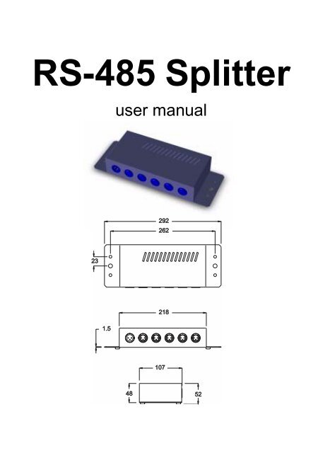
<strong>RS</strong>-<strong>485</strong> <strong>Splitter</strong><br />
user manual<br />
292<br />
262<br />
23<br />
1.5<br />
218<br />
107<br />
48<br />
52
Thank you for selecting the Martin <strong>RS</strong>-<strong>485</strong> <strong>Splitter</strong>. This optically isolated<br />
splitter/amplifier allows you to add 4 branches to the data link. Optical isolation<br />
of each branch increases link reliability by preventing a failure on one<br />
branch from interfering with operation on other branches. Amplification of the<br />
signal output allows the link to be extended over longer runs.<br />
The <strong>RS</strong>-<strong>485</strong> <strong>Splitter</strong> may be used equally well with DMX and Martin protocols.<br />
Several <strong>Splitter</strong>s may be used on the same link if additional branches are<br />
required.<br />
Installation and use is simple; please read the following notes to get the most<br />
out of the device.<br />
Safety Precautions<br />
• The device is not for domestic use.<br />
• Use the device only as described.<br />
• Do not expose the device to rain or moisture.<br />
• Make sure the device is properly grounded.<br />
• Use only a source of AC power that complies with local building and<br />
electrical codes and has both overload and ground-fault protection.<br />
• Do not operate the device with the cover removed.<br />
• Unplug the device before servicing.<br />
• Never replace the fuse with one of a higher rating.<br />
• Immediately repair or replace damaged power cords.<br />
Powering the <strong>RS</strong>-<strong>485</strong> <strong>Splitter</strong><br />
Warning! For safe operation, the device must be grounded (earthed).<br />
Check voltage setting<br />
The <strong>RS</strong>-458 <strong>Splitter</strong> may be switched between 115 and 230 V. Make sure the<br />
switch, located on the back, is correctly set before applying electricity.<br />
Install plug<br />
The <strong>RS</strong>-<strong>485</strong> <strong>Splitter</strong> is delivered without a plug on the power cord. Following<br />
the manufacturer’s instructions, install an approved 3-prong grounding-type<br />
plug that fits your supply. Connect the wires to the pins as listed below. Note:<br />
The table shows some possible pin identification schemes; if the pins are not<br />
clearly identified, or if you have any doubts about proper installation, consult a<br />
qualified electrician.<br />
P/N 35000009, Rev E.<br />
© 1998, 2004 Martin Professional A/S, Denmark. All rights reserved.
Wire Pin Typical US UK<br />
brown live “L”<br />
yellow or<br />
brass<br />
red<br />
blue neutral “N” silver black<br />
yellow/green<br />
ground<br />
(earth)<br />
green<br />
green<br />
A diode on the front panel lights when power is on.<br />
Connecting the <strong>RS</strong>-<strong>485</strong> <strong>Splitter</strong><br />
Input<br />
Connect the link cable from the controller to the “IN” jack on the <strong>Splitter</strong> using<br />
a 3-pin female XLR connector. Note: though the connections are labelled pin-<br />
2 hot and pin-3 cold, the <strong>Splitter</strong> works equally well with pin-2 cold and pin-3<br />
hot. Signal polarity is maintained: pin 2 on the input is wired to pin 2 on the<br />
outputs<br />
Signal Thru<br />
The data link may be continued normally by connecting it to the “THRU” jack -<br />
use a 3-pin XLR male connector. The signal from the “THRU” jack is not<br />
amplified or optically isolated. Insert a termination plug in the “THRU” jack<br />
if it is not used.<br />
Signal Output<br />
Connect up to 4 branches of the data link to the “OUT 1” - “OUT 4” jacks<br />
using 3-pin XLR male connectors. Each branch can have up to 32 fixtures<br />
connected and must be terminated. Unused outputs, however, do not need to<br />
be terminated.<br />
Replacing the fuse<br />
1. Unplug the <strong>Splitter</strong>. Remove 2 screws from each side and lift off the<br />
cover.<br />
2. Locate the fuse on the circuit board and replace with one of the<br />
same rating.<br />
3. Replace the cover and screws.<br />
Note: If the fuse blows repeatedly, there is a malfunction with the unit that<br />
must be referred to a service technician.
Specifications<br />
Dimensions<br />
• Length ..................................................................292 mm (11.5 in)<br />
• Width....................................................................107 mm (4.21 in)<br />
• Height.....................................................................52 mm (2.05 in)<br />
• Weight ...................................................................... 1.4 kg (3.1 lb)<br />
Electrical<br />
• Power supply settings ......................... 115/230 V, switch selectable<br />
• AC frequency..................................................................50 - 60 Hz<br />
• Fuse .................................................time delay (T) 0.125 A / 250 V<br />
Construction<br />
• Housing .................................................................................. steel<br />
• Finish ..................................................electrostatic powder coating<br />
Front Panel Jacks<br />
• Input ...................................................................... 3 pin XLR male<br />
• Thru .................................................................... 3 pin XLR female<br />
• Outputs ..........................................................4 x 3 pin XLR female<br />
Data Link<br />
• Electrical standard ............................................................. EIA-<strong>485</strong><br />
• Cable type ..................................................... shielded twisted pair<br />
• Cable gauge ............................................................ 22 or 24 AWG<br />
• Cable impedance ...................................................................120 Ω<br />
• Maximum length per branch, 22 AWG ..................... 500 m (1640 ft)<br />
• Maximum length per branch, 24 AWG ..................... 300 m (1000 ft)<br />
• Maximum load per branch ...............................................32 fixtures