RS-485 Splitter
RS-485 Splitter
RS-485 Splitter

Create successful ePaper yourself
Turn your PDF publications into a flip-book with our unique Google optimized e-Paper software.
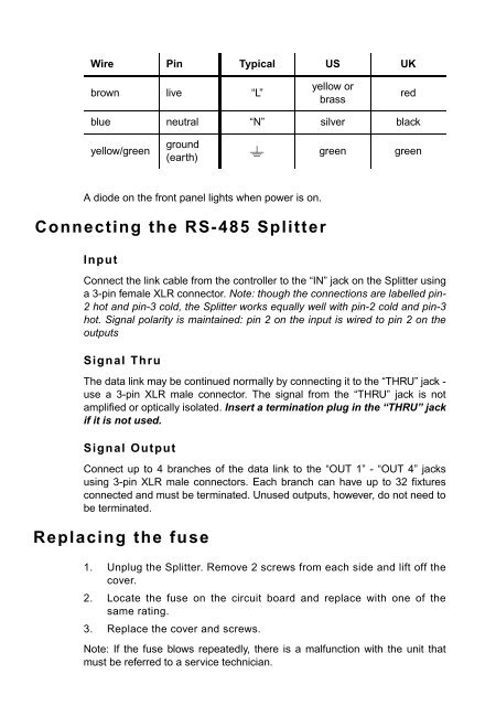
Wire Pin Typical US UK<br />
brown live “L”<br />
yellow or<br />
brass<br />
red<br />
blue neutral “N” silver black<br />
yellow/green<br />
ground<br />
(earth)<br />
green<br />
green<br />
A diode on the front panel lights when power is on.<br />
Connecting the <strong>RS</strong>-<strong>485</strong> <strong>Splitter</strong><br />
Input<br />
Connect the link cable from the controller to the “IN” jack on the <strong>Splitter</strong> using<br />
a 3-pin female XLR connector. Note: though the connections are labelled pin-<br />
2 hot and pin-3 cold, the <strong>Splitter</strong> works equally well with pin-2 cold and pin-3<br />
hot. Signal polarity is maintained: pin 2 on the input is wired to pin 2 on the<br />
outputs<br />
Signal Thru<br />
The data link may be continued normally by connecting it to the “THRU” jack -<br />
use a 3-pin XLR male connector. The signal from the “THRU” jack is not<br />
amplified or optically isolated. Insert a termination plug in the “THRU” jack<br />
if it is not used.<br />
Signal Output<br />
Connect up to 4 branches of the data link to the “OUT 1” - “OUT 4” jacks<br />
using 3-pin XLR male connectors. Each branch can have up to 32 fixtures<br />
connected and must be terminated. Unused outputs, however, do not need to<br />
be terminated.<br />
Replacing the fuse<br />
1. Unplug the <strong>Splitter</strong>. Remove 2 screws from each side and lift off the<br />
cover.<br />
2. Locate the fuse on the circuit board and replace with one of the<br />
same rating.<br />
3. Replace the cover and screws.<br />
Note: If the fuse blows repeatedly, there is a malfunction with the unit that<br />
must be referred to a service technician.