Distributed Antenna Systems - AWE-Communications
Distributed Antenna Systems - AWE-Communications
Distributed Antenna Systems - AWE-Communications

Create successful ePaper yourself
Turn your PDF publications into a flip-book with our unique Google optimized e-Paper software.
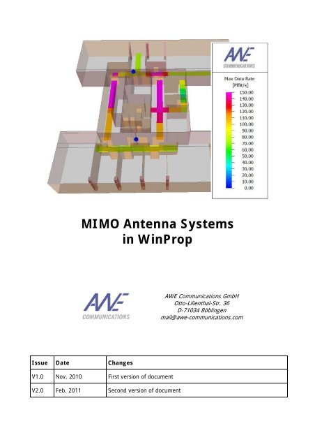
MIMO <strong>Antenna</strong> <strong>Systems</strong><br />
in WinProp<br />
<strong>AWE</strong> <strong>Communications</strong> GmbH<br />
Otto-Lilienthal-Str. 36<br />
D-71034 Böblingen<br />
mail@awe-communications.com<br />
Issue Date Changes<br />
V1.0 Nov. 2010 First version of document<br />
V2.0 Feb. 2011 Second version of document
MIMO <strong>Antenna</strong> <strong>Systems</strong> in WinProp 1<br />
1 Motivation<br />
Multiple-input and multiple-output (MIMO) technology is the use of multiple antennas at both the<br />
transmitter and receiver to improve communication performance. MIMO technology has attracted<br />
attention in wireless communications, because it offers significant increases in data throughput<br />
and link range without additional bandwidth or transmit power. It achieves this by higher spectral<br />
efficiency (more bits per second per hertz of bandwidth) and link reliability or diversity (reduced<br />
fading). Because of these properties, MIMO is an important part of modern wireless<br />
communication standards such as WiMAX, HSPA+, 3GPP Long Term Evolution, 4G, and IEEE<br />
802.11n (Wifi).<br />
Figure 1: Conventional SISO antenna system (top) and MIMO antenna system (bottom)<br />
The MIMO antenna configuration can be used for spatial multiplexing. In this case a high rate<br />
signal is split into multiple lower rate streams and each stream is transmitted from a different<br />
transmit antenna in the same frequency channel (see Figure 1). If these signals arrive at the<br />
receiver antenna array with sufficiently different spatial signatures, the receiver can separate these<br />
streams into (almost) parallel channels.<br />
Accordingly the spatial multiplexing by using MIMO antennas is a very powerful technique for<br />
increasing channel capacity at higher signal-to-noise-and-interference ratios (SNIR). The maximum<br />
number of spatial streams is limited by the lesser in the number of antennas at the transmitter or<br />
receiver.<br />
Typical MIMO schemes are MIMO 2x2 (i.e. two antennas each at both transmitter and receiver),<br />
and MIMO 4x4. In case of spatial multiplexing each MIMO antenna element transmits a separate<br />
MIMO data stream. The MIMO scheme 4x2 transmits the MIMO stream 1 from two antenna<br />
elements and the MIMO stream 2 from two other antenna elements, thus combining MIMO with a<br />
distributed antenna system (DAS). The receiver includes also two antenna elements (for<br />
separating the two different MIMO streams).<br />
© by <strong>AWE</strong> <strong>Communications</strong> GmbH
MIMO <strong>Antenna</strong> <strong>Systems</strong> in WinProp 2<br />
2 Modelling in WinProp<br />
For considering MIMO antennas in the WinProp radio network planning project first the<br />
corresponding MIMO scheme has to be selected on the air interface page (see Figure 2).<br />
Depending on the selected MIMO scheme a corresponding number of separate MIMO data streams<br />
is considered (either MIMO 2x2 with two parallel streams or MIMO 4x4 with four parallel streams).<br />
Figure 2: Air interface definition including MIMO technology<br />
Under the settings button further properties of the MIMO antenna system can be specified (see<br />
Figures 3 and 4).<br />
© by <strong>AWE</strong> <strong>Communications</strong> GmbH
MIMO <strong>Antenna</strong> <strong>Systems</strong> in WinProp 3<br />
Signaling Overhead<br />
When transmitting multiple data streams in parallel due to spatial multiplexing there is an<br />
additional signaling overhead required which reduces the effective achievable data rate. The<br />
defined value is considered once for MIMO 2x2 and twice for MIMO 4x4.<br />
Beamforming<br />
Figure 3: MIMO settings regarding beamforming<br />
Beamforming at the transmitter can be achieved by spatial processing. In this case the same<br />
signal is emitted from each of the transmit antennas with appropriate phase weighting such that<br />
the signal power is maximized at the receiver input.<br />
The benefits of beamforming are to increase the received signal gain, by making signals emitted<br />
from different antennas add up constructively, and to reduce the multipath fading effect. Spatial<br />
multiplexing can also be combined with beamforming when the channel is known at the<br />
transmitter.<br />
In the absence of scattering, beamforming results in a well defined directional pattern, thus<br />
increasing the antenna gain for the desired signal and reducing the antenna gain for the<br />
interfering signal. Consequently the antenna gains for the serving and interfering signals can be<br />
defined in the MIMO settings (see Figure 3) if beamforming is utilized. These values shall be kept<br />
to 0 dB if no beamforming is applied.<br />
© by <strong>AWE</strong> <strong>Communications</strong> GmbH
MIMO <strong>Antenna</strong> <strong>Systems</strong> in WinProp 4<br />
Interference between MIMO streams<br />
Spatial multiplexing by using MIMO antennas allows to increase the throughput depending on the<br />
signal-to-noise-and-interference ratio (SNIR). The SNIR is also influenced by the interference<br />
between the different MIMO streams.<br />
The MIMO settings page provides three different options for this purpose (see Figure 4):<br />
o No interference (ideal separation of different streams)<br />
If different polarizations are used (e.g. vertical polarization for MIMO stream 1 and<br />
horizontal polarization for MIMO stream 2) the streams are well separated, especially in<br />
LOS areas. Thus a simple assumption consists in neglecting the interference between the<br />
different MIMO streams.<br />
o Relative contribution to interference due to non-ideal separation of streams<br />
In this case an overall ratio for the interference between the different streams is specified.<br />
E.g. 20 dB which means that for a MIMO 2x2 system the received power for MIMO stream<br />
1 will increase the interference level for MIMO stream 2 (i.e. received power minus 20 dB)<br />
and vice versa. This option considers a constant relative interference impact over the whole<br />
simulation area (considering the individual received power values for each stream at each<br />
location).<br />
o Location dependent determination of interference due to non-ideal separation of streams<br />
This option considers the individual receiver location and the properties of the<br />
corresponding radio link (LOS/NLOS) for the interference impact. In order to ensure high<br />
accuracy the user shall define if different polarizations are used for the individual MIMO<br />
streams (e.g. vertical polarization for MIMO stream 1 and horizontal polarization for MIMO<br />
stream 2), which reduces the interference, especially in LOS conditions.<br />
Figure 4: MIMO settings regarding the interference between different MIMO streams<br />
© by <strong>AWE</strong> <strong>Communications</strong> GmbH
MIMO <strong>Antenna</strong> <strong>Systems</strong> in WinProp 5<br />
<strong>Antenna</strong> Definition<br />
Generally the antennas belonging to MIMO systems are defined in the same way than conventional<br />
antennas, i.e. location, carrier frequency, and transmit power of the antennas are defined as<br />
usual. For each MIMO antenna element a separate antenna has to be defined in<br />
ProMan.<br />
The so called Signal Group has to be set to the same ID for all antennas belonging to a MIMO<br />
system. Furthermore the transmitted MIMO stream has to be selected.<br />
For conventional antennas the Signal Group ID is set to individual (thus no MIMO stream can be<br />
selected). Generally all antennas belonging to a MIMO system must have the same carrier.<br />
Depending on the assigned Signal Group ID and the assigned MIMO stream the signals from<br />
different antennas are combined constructively or interfere each other.<br />
<strong>Antenna</strong> Type Signal Group MIMO Stream<br />
Conventional antenna Individual Not available<br />
<strong>Antenna</strong> belonging to DAS A / B / C / … No MIMO<br />
<strong>Antenna</strong> belonging to MIMO A / B / C / … MIMO stream 1 / stream 2<br />
The Signal Group and MIMO stream selection can be found in the carrier settings (see Figure 5) of<br />
a transmitter.<br />
Figure 5: Carrier settings for transmitter with Signal Group selection<br />
All antennas belonging to one MIMO system must have the same Signal Group ID. If only one<br />
MIMO system is available in your project it is recommended to use Signal Group A for all<br />
antennas which are part of the MIMO system.<br />
© by <strong>AWE</strong> <strong>Communications</strong> GmbH
MIMO <strong>Antenna</strong> <strong>Systems</strong> in WinProp 6<br />
3 Theory<br />
Computation of MIMO Results:<br />
For the computation of the MIMO result maps the received power (dBm) and the SNIR (dB) is<br />
computed for each defined MIMO stream (according to the specified MIMO scheme) in each<br />
receiver pixel. In this context also the interference between different MIMO streams operating on<br />
the same carrier (and Signal Group ID) is considered (depending on the selected option, see<br />
Figure 4). Finally the feasible modulation and coding scheme depending on the given SNIR is<br />
selected.<br />
If the serving cell is a MIMO antenna the received power is the superposition of the signal power<br />
values from all antennas belonging to the MIMO system and transmitting the same MIMO stream.<br />
<strong>Antenna</strong> Type<br />
Conventional antenna<br />
<strong>Antenna</strong> belonging to distributed<br />
antenna system (DAS)<br />
<strong>Antenna</strong> belonging to MIMO<br />
system<br />
Received Power<br />
Received power from serving cell<br />
Superposition of received power<br />
values from all antennas belonging<br />
to DAS of serving cell<br />
Superposition of received power<br />
values from all antennas<br />
transmitting the same MIMO<br />
stream as the serving cell<br />
Computation of Interference:<br />
Usually signals which are radiated on the same carrier but from different antennas interfere with<br />
each other as individual signals are transmitted. Signals which are radiated from different antennas<br />
but within the same DAS do not interfere (if they have the same Signal Group ID). If the<br />
antennas belong to a MIMO system the interference depends on the transmitted MIMO stream.<br />
<strong>Antenna</strong>s transmitting the same MIMO stream are considered to operate like a DAS (e.g. in a 4x2<br />
MIMO system). If the antennas transmit different MIMO streams they interfere each other<br />
depending on the individual situation (spatial separation, usage of different polarizations,<br />
LOS/NLOS scenario). The interfering effect can be reflected by selecting the appropriate option in<br />
the corresponding dialogue (see Figure 4).<br />
<strong>Antenna</strong> 1 <strong>Antenna</strong> 2<br />
Interference<br />
(same carrier)<br />
Conventional antenna Conventional antenna Yes<br />
Conventional antenna <strong>Antenna</strong> belonging to DAS A Yes<br />
<strong>Antenna</strong> belonging to DAS A <strong>Antenna</strong> belonging to DAS A No<br />
<strong>Antenna</strong> belonging to DAS A<br />
MIMO Stream 1<br />
<strong>Antenna</strong> belonging to DAS A<br />
MIMO Stream 1<br />
<strong>Antenna</strong> belonging to DAS A<br />
MIMO Stream 1<br />
<strong>Antenna</strong> belonging to DAS A<br />
MIMO Stream 2<br />
No<br />
Yes<br />
<strong>Antenna</strong> belonging to DAS A <strong>Antenna</strong> belonging to DAS B Yes<br />
© by <strong>AWE</strong> <strong>Communications</strong> GmbH
MIMO <strong>Antenna</strong> <strong>Systems</strong> in WinProp 7<br />
4 Example<br />
This section presents an example for the better understanding of the MIMO feature in WinProp.<br />
Figure 6 shows an office scenario with two antennas (distributed MIMO system). Both antennas<br />
use the same carrier - otherwise there would be no co-channel interference in the scenario.<br />
Site 1<br />
Site 2<br />
Figure 6: Office scenario with two antennas (DAS or MIMO 2x2)<br />
The main parameters of the network are shown in the following table.<br />
Parameter<br />
Frequency<br />
System bandwidth<br />
Transmit power<br />
<strong>Antenna</strong> height<br />
Min. required SNIR<br />
(depending on MCS)<br />
Air interface<br />
Value<br />
2630 MHz<br />
20 MHz<br />
5 dBm Output power of PA<br />
2.5 m<br />
Between –5.4 and 17.2 dB<br />
LTE<br />
Two different antenna configurations are analyzed in the following:<br />
• Configuration 1: Both sites are conventional antennas forming a DAS (Signal Group A).<br />
• Configuration 2: Both sites are MIMO antennas (Signal Group A) and transmit individual<br />
MIMO streams (site 1 MIMO stream 1 and site 2 MIMO stream 2).<br />
Figure 7 and Figure 8 show the data rate maps for these two configurations.<br />
© by <strong>AWE</strong> <strong>Communications</strong> GmbH
MIMO <strong>Antenna</strong> <strong>Systems</strong> in WinProp 8<br />
Site 1<br />
DAS:<br />
Signal Group A<br />
Site 2<br />
Figure 7: Max. data rate (DL) for DAS network (configuration 1)<br />
Site 1<br />
MIMO 2x2:<br />
Signal Group A<br />
Site 2<br />
Figure 8: Max. data rate (DL) for MIMO 2x2 network (configuration 2)<br />
© by <strong>AWE</strong> <strong>Communications</strong> GmbH
MIMO <strong>Antenna</strong> <strong>Systems</strong> in WinProp 9<br />
In Figure 7 (configuration 1) both antennas operate on the same carrier and form a distributed<br />
antenna system. Because of that the signals from both antennas are superposed constructively<br />
and improve the SNIR situation. Nevertheless the max. data rate is limited to 75 Mbit/s as only<br />
one data stream can be transmitted.<br />
Figure 8 shows configuration 2 where again both antennas operate on the same carrier, but this<br />
time sites 1 and 2 form a 2x2 MIMO system. Here MIMO stream 1 is transmitted from site1 and<br />
MIMO stream 2 is transmitted from site 2 in spatial multiplex. Accordingly higher data rates can be<br />
achieved for a large part of the office building (assuming here ideal separation of the different<br />
MIMO streams). Generally the performance depends also on the interference between the MIMO<br />
streams (see page 4).<br />
Figure 9: Max. data rate (DL) for MIMO 2x2 network with visualised MIMO streams<br />
Figure 9 shows the active MIMO streams 1 and 2 contributing to the max. data rate for a specific<br />
pixel (red shows the best received stream with the max. data rate, in dark red color the other<br />
MIMO streams are given).<br />
© by <strong>AWE</strong> <strong>Communications</strong> GmbH