4-way thermostat adaptable valves for two-pipes ... - Watts Industries
4-way thermostat adaptable valves for two-pipes ... - Watts Industries
4-way thermostat adaptable valves for two-pipes ... - Watts Industries

You also want an ePaper? Increase the reach of your titles
YUMPU automatically turns print PDFs into web optimized ePapers that Google loves.
4-<strong>way</strong> <strong>thermostat</strong> <strong>adaptable</strong><br />
<strong>valves</strong> <strong>for</strong> <strong>two</strong>-<strong>pipes</strong> and one-pipe<br />
heating systems Serie 120B - 102M<br />
Main features<br />
- Available in the following versions with :<br />
• Connection to heat emitter ND 1/2” - 3/4 “<br />
• Connection to copper or plastic pipe<br />
ND 1/2” - 1/2 “ S<br />
- Plug stroke presetting device<br />
- Con<strong>for</strong>ms with UNI 7942/79 standard
4-WAY THERMOSTAT ADAPTABLE VALVES<br />
Description<br />
2<br />
The 4-<strong>way</strong> <strong>thermostat</strong> <strong>adaptable</strong> <strong>valves</strong>, Series 120B, 102M, are used as shut-off and control devices <strong>for</strong><br />
radiators in <strong>two</strong>-pipe and one-pipe heating systems respectively.<br />
The <strong>valves</strong> come in the configuration with 1/2” - 3/4” connection to the heat emitter and are provided with probe<br />
<strong>for</strong> separating the delivery flow from the return flow in the radiator.<br />
Connection of the <strong>valves</strong> to the heat emitter is through an O-ring sealed straight tailpiece and final washer with<br />
the aid of a hex. spanner.<br />
120B<br />
4-<strong>way</strong> nickel-plated <strong>thermostat</strong> <strong>adaptable</strong> valve <strong>for</strong> <strong>two</strong>-pipe systems.<br />
With presetting. Built-in lockshield valve. Connection <strong>for</strong> copper or plastic pipe.<br />
O-ring sealed straight tailpiece, complete with flow separation probe. ABS<br />
handwheel. Differential pressure (item 148): 1.5 bar.<br />
Compatible with <strong>thermostat</strong>ic actuators series 148 and electrothermic actuators 22C.<br />
Type Part Number Size body Size tube Kvs Weight (g)<br />
120B 120B12AM12 1/2" 1/2" 0,82 570<br />
120B 120B12AM34 3/4" 1/2" 0,93 570<br />
120B 120B24AM12 1/2" 1/2"S 0,82 580<br />
120B 120B24AM34 3/4" 1/2"S 0,93 580<br />
102M<br />
4-<strong>way</strong> nickel-plated <strong>thermostat</strong> <strong>adaptable</strong> valve <strong>for</strong> one-pipe systems with fixed<br />
by-pass. With presetting. Built-in lockshield valve. Connection <strong>for</strong> copper or<br />
plastic pipe. O-ring sealed straight tailpiece, complete with flow separation probe.<br />
ABS handwheel. Differential pressure (item 148) : 1.5 bar.<br />
Flow rate to radiator: 50%.<br />
Compatible with <strong>thermostat</strong>ic actuators series 148 and electrothermic actuators 22C.<br />
Type Part Number Size body Size tube Kvs Weight (g)<br />
102M 102M12AM12 1/2" 1/2" 2 560<br />
102M 102M12AM34 3/4" 1/2" 2,15 560<br />
102M 102M24AM12 1/2" 1/2"S 2 570<br />
102M 102M24AM34 3/4" 1/2"S 2,15 580<br />
Technical feature<br />
Max. temp. 110°C<br />
Max. pressure<br />
10 bar<br />
Max. differential pressure<br />
1.5 bar<br />
Fluids which can be used Water also with glycol ≤ 50%<br />
120B<br />
102M<br />
Kvn coefficient with proportional band 2K DN 1/2" = 1.76 DN 3/4" = 1.84<br />
DN 1/2" = 0.58 DN 3/4" = 0.62<br />
Kvn coefficient with proportional band 1K DN 1/2" = 1.56 DN 3/4" = 1.61<br />
DN 1/2" = 0.34 DN 3/4" = 0.38<br />
Design feature<br />
Valve body<br />
Plug seal<br />
Handwheel<br />
Radiator probe<br />
Panel radiator probe<br />
O-ring<br />
Tailpiece<br />
Brass CW617N<br />
EPDM<br />
ABS<br />
Modified polyether (PPE + PA)<br />
Copper<br />
EPDM<br />
Brass CW617N
4-WAY THERMOSTAT ADAPTABLE VALVES<br />
Application<br />
These <strong>valves</strong> are designed <strong>for</strong> manual room temperature control using just one connection <strong>for</strong> water inlet/outlet<br />
to/from the heat emitter. They can also be used <strong>for</strong> automatic temperature control when coupled to <strong>thermostat</strong>ic<br />
actuators (Series 148, 148SD, 148CD) or else electrothermic actuators (Art. 22C). The use of <strong>thermostat</strong>ic<br />
<strong>valves</strong> allows installation of metering systems (see Sections on Measuring and metering systems) as required by<br />
Italian legislation (Act 10/91 Art. 26). The <strong>valves</strong> are provided with active memory presetting which, when using<br />
<strong>thermostat</strong>ic or thermoelectric actuators, enables exact balancing of the heating system.<br />
3<br />
Such balancing is obtained by turning the ring nut located under the handwheel in order to limit the plug stroke.<br />
Above all, when removing the handwheel <strong>for</strong> <strong>thermostat</strong>ting the system, the active memory presetting holds the<br />
balancing made permanently.<br />
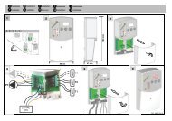
Installation<br />
Valve selection is based on the type of system (one-pipe or <strong>two</strong>-pipe) as well as size of the connection to the<br />
radiator and connecting piping. Valves, Series 120B, 102M, can be installed on heat emitters supplied by<br />
copper or plastic <strong>pipes</strong>. When it is required to <strong>thermostat</strong> the system, merely unscrew the control handwheel from<br />
the valve and substitute it with a <strong>thermostat</strong>ic or electrothermic actuator by tightening the ring nut.<br />
All this can be done without any plumbing work and with the system running. As with all the <strong>two</strong>-pipe and<br />
one-pipe <strong>valves</strong>, likewise <strong>valves</strong> 120B, 102M should be connected in the bottom part of the heat emitter.<br />
In order to ensure correct <strong>thermostat</strong>ic operation (i.e. with <strong>thermostat</strong>ic actuator Series 148), the delivery pipe<br />
must be connected to the connection under the valve control handwheel which should al<strong>way</strong>s be mounted in the<br />
horizontal direction. In the case of panel type radiators, use the copper probe (art. RV141). When excluding and<br />
removing the radiator, it is also necessary to regulate the special built-in lockshield. All this should be done<br />
without interrupting circulation of the fluid in the rest of the ring circuit.<br />
Reliability of the <strong>thermostat</strong> <strong>adaptable</strong> <strong>valves</strong>, Series 120B, 102M, is guaranteed thanks to the 100% testing of<br />
the production which checks pressure tightness of the valve body and its components towards the outside and<br />
that of the plug during its flow shut-off function.<br />
102M<br />
4<br />
3<br />
1<br />
2<br />
Details<br />
5<br />
1) O-ring sealed straight tailpiece<br />
2) Probe holder insert<br />
3) Lockshield<br />
120B<br />
4) Presetting stuffing box nut, can be<br />
replaced with the system under<br />
pressure through art. 225.<br />
4<br />
3<br />
1<br />
2<br />
5) By-pass
4-WAY THERMOSTAT ADAPTABLE VALVES<br />
Operation<br />
4<br />
Valve operation is controlled either by manual movement or by automatic movement of the plug which shuts off<br />
the heat carrier fluid.<br />
In <strong>valves</strong> of the 102M series, known as partial flow types <strong>for</strong> one-pipe systems, the water flow calculated <strong>for</strong> the<br />
entire ring circuit, is subdivided into one part <strong>for</strong> heat exchange and one part reaching the next heat emitter<br />
directly. This permanently open by-pass allows constant circulation of the heat carrier fluid even when the valve<br />
is fully closed with respect to the heat emitter. In <strong>valves</strong> of the 120B series <strong>for</strong> <strong>two</strong>-pipe systems, the flow of<br />
water reaches the heat emitter directly where the heat exchange takes place.<br />
To ensure efficiency of this, in <strong>valves</strong> Series 120B, 102M, the delivery and return flow is separated by a probe<br />
inserted in the heat emitter. The hydraulic flow rate and pressure drop cahracteristics <strong>for</strong> the <strong>valves</strong> can be<br />
deduced from the appropriate charts.<br />
102M<br />
Total Kv values (flow rate towards radiator + by-pass flow rate) Setting positions<br />
Setting positions 1 2 3 4 5 6 7 A<br />
DN 1/2" 1.50 1.60 1.75 1.80 1.85 1.90 1.95 2.00<br />
DN 3/4" 1.55 1.75 1.90 1.95 2.00 2.05 2.10 2.15<br />
102M<br />
“Supply coefficient” of the heating emitter, expressed in percentage<br />
of the flow passing through the distribution ring circuit is equal to:<br />
DN 1 2 3 4 5 6 7 A<br />
DN 1/2" - 3/4" 22% 30% 34% 36% 38% 40% 42% 50%<br />
120B - 102M<br />
Kv values in the various presetting positions<br />
Setting positions 1 2 3 4 5 6 7 A<br />
DN 1/2" 0.30 0.53 0.63 0.70 0.74 0.77 0.79 0.82<br />
DN 3/4" 0.30 0.56 0.67 0.75 0.81 0.85 0.88 0.93<br />
Overall dimension (mm)<br />
120B/102M<br />
105<br />
30 60<br />
70<br />
35
4-WAY THERMOSTAT ADAPTABLE VALVES<br />
Flow rate/pressure drop charts<br />
120B - DN 1/2" - 3/4"<br />
pos 3 Kv 0.65<br />
pos 4 Kv 0.73<br />
5<br />
pos 2 Kv 0.55<br />
pos 6 Kv 0.81<br />
[ kPa ]<br />
pos 1 Kv 0.30<br />
A Kv 0.88<br />
[ m bar ] [ mm w.g. ]<br />
20<br />
200<br />
2000<br />
10<br />
8<br />
100<br />
80<br />
1000<br />
800<br />
5<br />
4<br />
50<br />
40<br />
500<br />
400<br />
PRESSURE DROP<br />
3<br />
2<br />
1<br />
0.8<br />
0.5<br />
30<br />
20<br />
10<br />
5<br />
300<br />
200<br />
100<br />
50<br />
0.3<br />
3<br />
30<br />
0.2<br />
2<br />
20<br />
0.1<br />
1<br />
10 20 30 50 100 200 300 500 1000 2000 3000 [ l/h ]<br />
10<br />
0.01 0.02 0.03 0.05 0.1 0.2 0.3 0.5 1 2 3<br />
3<br />
[ m /h ]<br />
FLOW RATE<br />
With actuator 148<br />
120B - DN 1/2" - 3/4"<br />
BP 3K=Kv 0.7<br />
BP 2K=Kv 0.6<br />
[ kPa ]<br />
BP 1K=Kv 0.36<br />
[ m bar ][ mm w.g. ]<br />
20<br />
200<br />
2000<br />
10<br />
8<br />
100<br />
80<br />
1000<br />
800<br />
PRESSURE DROP<br />
5<br />
4<br />
3<br />
2<br />
1<br />
0.8<br />
0.5<br />
50<br />
40<br />
30<br />
20<br />
10<br />
5<br />
500<br />
400<br />
300<br />
200<br />
100<br />
50<br />
0.3<br />
3<br />
30<br />
0.2<br />
2<br />
20<br />
0.1<br />
1<br />
10 20 30 50 100 200 300 500 1000 2000 3000 [ l/h ]<br />
10<br />
0.01 0.02 0.03 0.05 0.1 0.2 0.3 0.5 1 2 3<br />
3<br />
[ m /h ]<br />
FLOW RATE
4-WAY THERMOSTAT ADAPTABLE VALVES<br />
Flow rate/pressure drop charts<br />
6<br />
102M - DN 1/2"<br />
pos 3 Kv 1.75<br />
pos 1 Kv 1.50 A Kv 2.00<br />
[ kPa ]<br />
20<br />
By-Pass Kvs 1.25<br />
[ m bar ][ mm w.g. ]<br />
200<br />
2000<br />
10<br />
8<br />
100<br />
80<br />
1000<br />
800<br />
PRESSURE DROP<br />
5<br />
4<br />
3<br />
2<br />
1<br />
0.8<br />
0.5<br />
50<br />
40<br />
30<br />
20<br />
10<br />
5<br />
500<br />
400<br />
300<br />
200<br />
100<br />
50<br />
0.3<br />
3<br />
30<br />
0.2<br />
2<br />
20<br />
0.1<br />
1<br />
10 20 30 50 100 200 300 500 1000 2000 3000 [ l/h ]<br />
10<br />
0.01 0.02 0.03 0.05 0.1 0.2 0.3 0.5 1 2 3<br />
3<br />
[ m /h ]<br />
FLOW RATE<br />
With actuator 148<br />
102M - DN 1/2"<br />
BP 2K=Kv 1.76<br />
[ kPa ]<br />
20<br />
BP 1K=Kv 1.56<br />
[ m bar ][ mm w.g. ]<br />
200 2000<br />
10<br />
8<br />
100<br />
80<br />
1000<br />
800<br />
PRESSURE DROP<br />
5<br />
4<br />
3<br />
2<br />
1<br />
0.8<br />
0.5<br />
50<br />
40<br />
30<br />
20<br />
10<br />
5<br />
500<br />
400<br />
300<br />
200<br />
100<br />
50<br />
0.3<br />
3<br />
30<br />
0.2<br />
2<br />
20<br />
0.1<br />
1<br />
10 20 30 50 100 200 300 500 1000 2000 3000<br />
[ l/h ]<br />
10<br />
0.01 0.02 0.03 0.05 0.1 0.2 0.3 0.5 1 2 3<br />
3<br />
[ m /h ]<br />
FLOW RATE
4-WAY THERMOSTAT ADAPTABLE VALVES<br />
102M - DN 3/4"<br />
pos 3 Kv 1.90<br />
[ kPa ]<br />
pos 1 Kv 1.55 A Kv 2.15<br />
[ m bar ][ mm w.g. ]<br />
7<br />
20<br />
200<br />
2000<br />
10<br />
8<br />
100<br />
80<br />
1000<br />
800<br />
PRESSURE DROP<br />
5<br />
4<br />
3<br />
2<br />
1<br />
0.8<br />
0.5<br />
50<br />
40<br />
30<br />
20<br />
10<br />
5<br />
500<br />
400<br />
300<br />
200<br />
100<br />
50<br />
0.3<br />
3<br />
30<br />
0.2<br />
2<br />
20<br />
0.1<br />
1<br />
10 20 30 50 100 200 300 500 1000 2000 3000 [ l/h ]<br />
10<br />
0.01 0.02 0.03 0.05 0.1 0.2 0.3 0.5 1 2 3<br />
3<br />
[ m /h ]<br />
FLOW RATE<br />
With actuator 148<br />
102M - DN 3/4"<br />
BP 2K=Kv 1.84<br />
[ kPa ]<br />
20<br />
BP 1K=Kv 1.61<br />
[ m bar ][ mm w.g. ]<br />
200 2000<br />
10<br />
8<br />
100<br />
80<br />
1000<br />
800<br />
PRESSURE DROP<br />
5<br />
4<br />
3<br />
2<br />
1<br />
0.8<br />
0.5<br />
0.3<br />
50<br />
40<br />
30<br />
20<br />
10<br />
5<br />
3<br />
500<br />
400<br />
300<br />
200<br />
100<br />
50<br />
30<br />
0.2<br />
2<br />
20<br />
0.1<br />
1<br />
10 20 30 50 100 200 300 500 1000 2000 3000<br />
[ l/h ]<br />
10<br />
0.01 0.02 0.03 0.05 0.1 0.2 0.3 0.5 1 2 3<br />
3<br />
[ m /h ]<br />
FLOW RATE<br />
The descriptions and photographs contained in this product specification sheet are supplied by <strong>way</strong> of in<strong>for</strong>mation only and are not binding.<br />
<strong>Watts</strong> <strong>Industries</strong> reserves the right to carry out any technical and design improvements to its products without prior notice.
Product range <strong>Watts</strong> <strong>Industries</strong><br />
- System disconnectors<br />
- Backflow protection devices<br />
- Check <strong>valves</strong><br />
- Safety units<br />
- Safety relief <strong>valves</strong><br />
- Pressure reducing <strong>valves</strong><br />
- Automatic control <strong>valves</strong><br />
- Butterfly <strong>valves</strong><br />
- Shut off <strong>valves</strong><br />
- Measuring gauges<br />
- Temperature control<br />
- Expansion vessels<br />
- Process switches<br />
- Fuel products<br />
- Gas products<br />
- Electronic controls<br />
- Installation protection products<br />
- Radiator <strong>valves</strong><br />
- System products<br />
- Manifolds and fittings<br />
Re-order no. 67-0030-UK-IT/1-06-01-Rev.0<br />
<strong>Watts</strong> <strong>Industries</strong> Italia S.r.l.<br />
Via Brenno, 21 - 20046 Biassono (MI), Italy<br />
Ph. : +39 039 49.86.1 - Fax : +39 039 49.86.222<br />
e-mail : info@wattsindustries.it - www.wattsindustries.com