Fano resonances in prism-coupled square micropillars
Fano resonances in prism-coupled square micropillars
Fano resonances in prism-coupled square micropillars

Create successful ePaper yourself
Turn your PDF publications into a flip-book with our unique Google optimized e-Paper software.
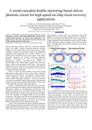
January 1, 2004 / Vol. 29, No. 1 / OPTICS LETTERS 5<br />
<strong>Fano</strong> <strong>resonances</strong> <strong>in</strong> <strong>prism</strong>-<strong>coupled</strong> <strong>square</strong> <strong>micropillars</strong><br />
Ho-Tong Lee and Andrew W. Poon<br />
Department of Electrical and Electronic Eng<strong>in</strong>eer<strong>in</strong>g, The Hong Kong University of Science and Technology,<br />
Clear Water Bay, Hong Kong SAR, Ch<strong>in</strong>a<br />
Received July 24, 2003<br />
We report <strong>Fano</strong> <strong>resonances</strong> <strong>in</strong> the frustrated total <strong>in</strong>ternal ref lection (TIR) spectra of a <strong>prism</strong>-<strong>coupled</strong> <strong>square</strong><br />
micropillar. Our angle-selective frustrated TIR technique reveals characteristically asymmetric resonance<br />
l<strong>in</strong>e shapes, which evolve spectrally over approximately a 2p phase <strong>in</strong> the far field with<strong>in</strong> a subdegree range<br />
of ref lection angles. We theoretically model the asymmetric l<strong>in</strong>e shapes by the <strong>in</strong>terference between a high-Q<br />
resonance that is evanescently <strong>coupled</strong> and partially conf<strong>in</strong>ed by TIR, and a coherent background that is total<br />
<strong>in</strong>ternally ref lected at the <strong>prism</strong> surface without coupl<strong>in</strong>g to the micropillar. © 2004 Optical Society of<br />
America<br />
OCIS codes: 230.5750, 260.5740.<br />
Optical <strong>resonances</strong> circulat<strong>in</strong>g <strong>in</strong> dielectric micropillar<br />
(m-pillar) cavities <strong>in</strong> the form of circular disks, 1 r<strong>in</strong>gs, 2<br />
and <strong>square</strong>s 3–5 have attracted considerable <strong>in</strong>terest for<br />
wavelength-division multiplex<strong>in</strong>g channel add–drop<br />
applications. It is well known that a light wave can<br />
be partially conf<strong>in</strong>ed by total <strong>in</strong>ternal ref lection (TIR)<br />
at the m-pillar sidewalls. When the m-pillar is <strong>in</strong>put<br />
side <strong>coupled</strong> by either a dielectric coupler 1–3,5 or a<br />
Gaussian beam, 4 optical <strong>resonances</strong> are excited when<br />
the cavity round-trip wave is wave-front matched<br />
with the <strong>in</strong>put <strong>coupled</strong> wave. The excited modes,<br />
without <strong>in</strong>terfer<strong>in</strong>g with a coherent background, are<br />
generally considered to have a symmetric Lorentzian<br />
l<strong>in</strong>e shape. 6 However, recent theoretical and numerical<br />
<strong>in</strong>vestigations revealed pronounced asymmetric<br />
resonance l<strong>in</strong>e shapes <strong>in</strong> waveguide-<strong>coupled</strong> optical<br />
microresonators. 7 Such characteristically asymmetric<br />
l<strong>in</strong>e shapes, known as <strong>Fano</strong> <strong>resonances</strong>, result<br />
from the <strong>in</strong>terference between a s<strong>in</strong>gle resonance and<br />
a cont<strong>in</strong>uum of background modes. Recently, <strong>Fano</strong><br />
<strong>resonances</strong> have also been found <strong>in</strong> two-dimensional<br />
nonl<strong>in</strong>ear photonic crystal slabs. 8<br />
In this Letter we report, for the first time to<br />
our knowledge, <strong>Fano</strong> <strong>resonances</strong> <strong>in</strong> frustrated TIR<br />
spectra of a <strong>prism</strong>-<strong>coupled</strong> <strong>square</strong> m-pillar. Our<br />
angle-selective frustrated TIR technique reveals<br />
characteristically asymmetric l<strong>in</strong>e shapes that evolve<br />
spectrally over an approximately 2p phase change<br />
<strong>in</strong> the far field with<strong>in</strong> a subdegree range of ref lection<br />
angles. We theoretically model the asymmetric<br />
l<strong>in</strong>e shapes by the <strong>in</strong>terference between a high-Q<br />
resonance that is evanescently <strong>coupled</strong> and partially<br />
conf<strong>in</strong>ed by TIR, and a coherent background that is<br />
total <strong>in</strong>ternally ref lected at the <strong>prism</strong> surface without<br />
coupl<strong>in</strong>g to the m-pillar.<br />
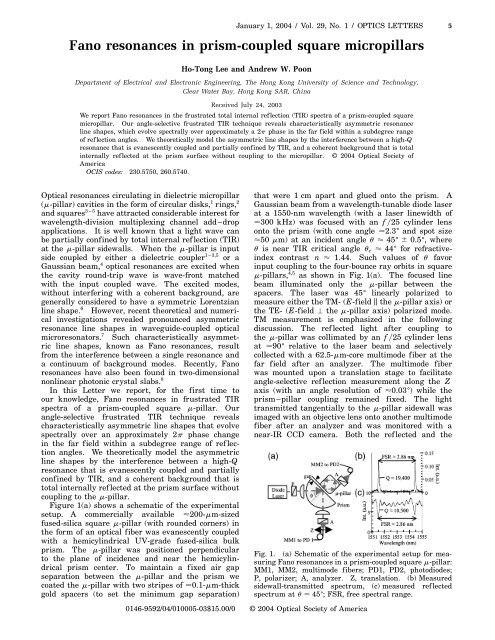
Figure 1(a) shows a schematic of the experimental<br />
setup. A commercially available 200-mm-sized<br />
fused-silica <strong>square</strong> m-pillar (with rounded corners) <strong>in</strong><br />
the form of an optical fiber was evanescently <strong>coupled</strong><br />
with a hemicyl<strong>in</strong>drical UV-grade fused-silica bulk<br />
<strong>prism</strong>. The m-pillar was positioned perpendicular<br />
to the plane of <strong>in</strong>cidence and near the hemicyl<strong>in</strong>drical<br />
<strong>prism</strong> center. To ma<strong>in</strong>ta<strong>in</strong> a fixed air gap<br />
separation between the m-pillar and the <strong>prism</strong> we<br />
coated the m-pillar with two stripes of 0.1-mm-thick<br />
gold spacers (to set the m<strong>in</strong>imum gap separation)<br />
that were 1 cm apart and glued onto the <strong>prism</strong>. A<br />
Gaussian beam from a wavelength-tunable diode laser<br />
at a 1550-nm wavelength (with a laser l<strong>in</strong>ewidth of<br />
300 kHz) was focused with an f 25 cyl<strong>in</strong>der lens<br />
onto the <strong>prism</strong> (with cone angle 2.3 ± and spot size<br />
50 mm) at an <strong>in</strong>cident angle u 45 ± 6 0.5 ± , where<br />
u is near TIR critical angle u c 44 ± for refractive<strong>in</strong>dex<br />
contrast n 1.44. Such values of u favor<br />
<strong>in</strong>put coupl<strong>in</strong>g to the four-bounce ray orbits <strong>in</strong> <strong>square</strong><br />
m-pillars, 4,5 as shown <strong>in</strong> Fig. 1(a). The focused l<strong>in</strong>e<br />
beam illum<strong>in</strong>ated only the m-pillar between the<br />
spacers. The laser was 45 ± l<strong>in</strong>early polarized to<br />
measure either the TM- (E-field k the m-pillar axis) or<br />
the TE- (E-field the m-pillar axis) polarized mode.<br />
TM measurement is emphasized <strong>in</strong> the follow<strong>in</strong>g<br />
discussion. The ref lected light after coupl<strong>in</strong>g to<br />
the m-pillar was collimated by an f 25 cyl<strong>in</strong>der lens<br />
at 90 ± relative to the laser beam and selectively<br />
collected with a 62.5-mm-core multimode fiber at the<br />
far field after an analyzer. The multimode fiber<br />
was mounted upon a translation stage to facilitate<br />
angle-selective ref lection measurement along the Z<br />
axis (with an angle resolution of 0.03 ± ) while the<br />
<strong>prism</strong>–pillar coupl<strong>in</strong>g rema<strong>in</strong>ed fixed. The light<br />
transmitted tangentially to the m-pillar sidewall was<br />
imaged with an objective lens onto another multimode<br />
fiber after an analyzer and was monitored with a<br />
near-IR CCD camera. Both the ref lected and the<br />
Fig. 1. (a) Schematic of the experimental setup for measur<strong>in</strong>g<br />
<strong>Fano</strong> <strong>resonances</strong> <strong>in</strong> a <strong>prism</strong>-<strong>coupled</strong> <strong>square</strong> m-pillar:<br />
MM1, MM2, multimode fibers; PD1, PD2, photodiodes;<br />
P, polarizer; A, analyzer. Z, translation. (b) Measured<br />
sidewall-transmitted spectrum, (c) measured ref lected<br />
spectrum at u 45 ± ; FSR, free spectral range.<br />
0146-9592/04/010005-03$15.00/0 © 2004 Optical Society of America
6 OPTICS LETTERS / Vol. 29, No. 1 / January 1, 2004<br />
transmitted spectra were lock-<strong>in</strong> detected with similar<br />
photodiodes. The spectral resolution was 0.03 nm,<br />
which was limited only by our data-tak<strong>in</strong>g rate.<br />
Figures 1(b) and 1(c) show the simultaneously<br />
measured TM-polarized sidewall-transmitted and<br />
-ref lected spectrum of the <strong>prism</strong>-<strong>coupled</strong> <strong>square</strong><br />
m-pillar. The free spectral range of both the ref lected<br />
(u 45 ± ) and the transmitted spectrum is 2.86 nm,<br />
consistent with the calculated free spectral range of<br />
wave-front-matched four-bounce orbits. 4 Only one<br />
set of modes is preferentially <strong>coupled</strong>. The ref lected<br />
spectrum [Fig. 1(c)] reveals approximately symmetric<br />
dips with a maximum Q exceed<strong>in</strong>g 10 4 , whereas the<br />
transmitted spectrum [Fig. 1(b)] shows approximately<br />
symmetric peaks with a higher Q (2 3 10 4 ). We attribute<br />
the difference <strong>in</strong> Q to the fact that the ref lected<br />
and transmitted spectra can orig<strong>in</strong>ate from different<br />
heights along the illum<strong>in</strong>ated m-pillar, which can have<br />
a nonuniform surface roughness or nonuniform gap<br />
spac<strong>in</strong>g. Figure 1(c) shows a coupl<strong>in</strong>g efficiency that<br />
exceeds 50%, which can be improved by narrow<strong>in</strong>g<br />
the air gap separation between the <strong>prism</strong> and the<br />
m-pillar. 5 The ripplelike modulation <strong>in</strong> Fig. 1(c)<br />
is due to residual Fabry–Perot <strong>in</strong>terference <strong>in</strong> the<br />
external-cavity diode laser.<br />
Figure 2 shows the measured TM-polarized angleselective<br />
spectra at ref lection angles from u 44.94 ±<br />
to u 45.71 ± . Characteristically asymmetric l<strong>in</strong>e<br />
shapes (<strong>Fano</strong> l<strong>in</strong>e shapes) can be clearly discerned<br />
<strong>in</strong> Figs. 2(b) and 2(d). The <strong>Fano</strong> l<strong>in</strong>e shapes evolve<br />
cont<strong>in</strong>ually over an approximately 2p phase change.<br />
The Q value measured <strong>in</strong> Fig. 2(a) exceeds 5000, and<br />
the coupl<strong>in</strong>g efficiency exceeds 68%. We observed<br />
that the <strong>Fano</strong> l<strong>in</strong>e-shape evolution repeats for another<br />
approximately 2p-phase change from u 44.45 ± to<br />
u 44.94 ± (not shown here).<br />
Figure 3 is a schematic of our theoretical model.<br />
We consider the far-field <strong>in</strong>terference between ray R,<br />
which is evanescently <strong>coupled</strong> to a high-Q <strong>square</strong><br />
cavity four-bounce mode, and ray B, which is a coherent<br />
background that is due to TIR at the <strong>prism</strong><br />
surface without coupl<strong>in</strong>g to the m-pillar. The <strong>in</strong>terference<br />
between an optical resonance and the coherent<br />
background is analogous to the <strong>in</strong>terference between<br />
a s<strong>in</strong>gle resonance and a cont<strong>in</strong>uum of background<br />
modes accord<strong>in</strong>g to the theory of <strong>Fano</strong> <strong>resonances</strong>.<br />
The <strong>square</strong> cavity has plane-to-plane distance a and<br />
a refractive <strong>in</strong>dex n m that is the same as that of the<br />
<strong>prism</strong>. The cavity is separated from the <strong>prism</strong> with<br />
air gap spac<strong>in</strong>g x and refractive <strong>in</strong>dex n a 1. Ray R<br />
is evanescently <strong>in</strong>put <strong>coupled</strong> to the <strong>square</strong> cavity<br />
at u u R , which satisfies the <strong>square</strong> cavity TIR<br />
conf<strong>in</strong>ement condition u c , u R , 90 ± 2 u c . 4 We<br />
express the resultant ref lected electric field amplitude<br />
E R (normalized to <strong>in</strong>cident field amplitude E 0 ) as<br />
follows 9 :<br />
where r FTIR and t FTIR are the frustrated TIR complex<br />
ref lection and transmission coefficients between<br />
semi-<strong>in</strong>f<strong>in</strong>ite dielectric media separated by an air<br />
gap, 9,10 f is the cavity round-trip phase shift, a is<br />
the cavity round-trip loss, and F R is the phase of<br />
E R relative to E 0 at the far field. We adopt a 2p2<br />
phase difference between r FTIR and t FTIR . 9,10 The<br />
wavelength-dependent value of f is given as<br />
fl 2pnLl 1g TIR , where L 2acos u1s<strong>in</strong> u<br />
is the wave-front-matched round-trip length 4 and g TIR<br />
is the TIR phase shift at the four cavity sidewalls. 10<br />
Ray B represents the coherent background that is<br />
due to TIR at the <strong>prism</strong> surface without coupl<strong>in</strong>g to the<br />
m-pillar. Such coherent background can be attributed<br />
to the fact that part of the laser beam may not spatially<br />
overlap the <strong>prism</strong>–pillar coupl<strong>in</strong>g region, as shown <strong>in</strong><br />
Fig. 2. Measured <strong>Fano</strong> <strong>resonances</strong> <strong>in</strong> TM-polarized ref lection<br />
spectra (a) u 45.71 ± , (b) u 45.49 ± , (c) u 45.27 ± ,<br />
(d) u 45.11 ± , (e) u 44.94 ± . Int., <strong>in</strong>tensity.<br />
E R<br />
E 0<br />
r FTIR 1 t FTIR 2 expifexp2a<br />
1 2 r FTIR expifexp2a<br />
<br />
Ç<br />
ER<br />
E 0<br />
Ç<br />
expiF R , (1)<br />
Fig. 3. Schematic of the theoretical model. Ray R is<br />
<strong>coupled</strong> to a four-bounce ray orbit. Ray B represents a<br />
coherent background that is total <strong>in</strong>ternally reflected at<br />
the <strong>prism</strong> surface without coupl<strong>in</strong>g to the cavity. The<br />
dashed arrow represents the surface wave leakage.
January 1, 2004 / Vol. 29, No. 1 / OPTICS LETTERS 7<br />
Fig. 4. Calculated resonance l<strong>in</strong>e shapes with a coherent<br />
background. x 800 nm, u R 44 ± , a 0.19.<br />
(a) jF R 2F B j 0, (b) jF R 2F B j 0.5p, (c) jF R 2F B j <br />
p, (d) jF R 2F B j 1.5p.<br />
Fig. 3. Moreover, it is conceivable that the m-pillar <strong>in</strong><br />
the experiment can have a lateral tilt angle of the order<br />
of 1 ± with the <strong>prism</strong>’s f lat surface, and thus even<br />
part of the laser beam illum<strong>in</strong>at<strong>in</strong>g the <strong>prism</strong>–pillar<br />
coupl<strong>in</strong>g region can be total <strong>in</strong>ternally ref lected without<br />
coupl<strong>in</strong>g to the m-pillar. We express the coherent<br />
TIR background electric field E B (normalized to E 0 )as<br />
E B E 0 expiF B , where F B is the phase of E B relative<br />
to E 0 at the far field.<br />
The evanescently <strong>coupled</strong> high-Q <strong>resonances</strong> (ray R)<br />
and the coherent TIR background (ray B) can spatially<br />
overlap and <strong>in</strong>terfere <strong>in</strong> the far field. The resultant<br />
ref lected <strong>in</strong>tensity I (normalized to <strong>in</strong>cident <strong>in</strong>tensity<br />
I 0 ) is given as follows:<br />
µÇ Ç<br />
I<br />
2<br />
∂ Ç Ç<br />
ER<br />
ER<br />
11 1 2 cosF R 2F B . (2)<br />
I 0 E 0 E 0<br />
Phase jF R 2F B j at resonance wavelength l 0 determ<strong>in</strong>es<br />
the asymmetric l<strong>in</strong>e shapes.<br />
Figure 4 shows the <strong>in</strong>terference <strong>in</strong>tensity calculated<br />
with Eq. (2). TM polarization (or s polarization 10 )is<br />
assumed. We chose a 200 mm, n m 1.44, u R 44 ± ,<br />
x 800 nm, and a 0.19 and found good agreement<br />
between the measured <strong>Fano</strong> l<strong>in</strong>e shapes (Fig. 2) and<br />
the l<strong>in</strong>e shapes calculated for jF R 2F B j 0, 0.5p, p,<br />
1.5p. The calculated <strong>resonances</strong> <strong>in</strong> Fig. 4(a) have a<br />
coupl<strong>in</strong>g efficiency of 69% and a Q value of 5000,<br />
which match those of Fig. 2(a).<br />
We remark that the evanescently <strong>coupled</strong> high-Q<br />
<strong>resonances</strong> can output couple tangentially as a surface<br />
wave along the cavity sidewall, shown as a dashed<br />
arrow <strong>in</strong> Fig. 3. Inasmuch as the <strong>square</strong> m-pillar is<br />
multimode, 4,5 it is conceivable that the high-Q resonance<br />
field and a cont<strong>in</strong>uum of multimodes (evanescently<br />
<strong>coupled</strong> by the Gaussian beam) can <strong>in</strong>terfere <strong>in</strong><br />
the far field and thus display <strong>Fano</strong> <strong>resonances</strong>.<br />
In conclusion, we have experimentally demonstrated<br />
<strong>Fano</strong> <strong>resonances</strong> by us<strong>in</strong>g angle-selective<br />
<strong>prism</strong> coupl<strong>in</strong>g to the high-Q optical <strong>resonances</strong> of a<br />
<strong>square</strong> m-pillar. Our frustrated TIR spectra revealed<br />
asymmetric l<strong>in</strong>e shapes, which evolve spectrally over<br />
approximately a 2p phase <strong>in</strong> the far field with<strong>in</strong> a<br />
subdegree range of angles. We theoretically modeled<br />
the measured <strong>Fano</strong> <strong>resonances</strong> by the <strong>in</strong>terference<br />
between a high-Q resonance that is evanescently<br />
<strong>coupled</strong> and partially TIR conf<strong>in</strong>ed, and a coherent<br />
background that is due to TIR at the <strong>prism</strong> surface<br />
without coupl<strong>in</strong>g to the m-pillar. We found good<br />
agreement between the measured and the calculated<br />
characteristically asymmetric l<strong>in</strong>e shapes. <strong>Fano</strong><br />
<strong>resonances</strong> <strong>in</strong> microresonators should be of particular<br />
<strong>in</strong>terest <strong>in</strong> relation to <strong>in</strong>tegrated optical switches and<br />
filters, for which the optical resonance l<strong>in</strong>e shapes can<br />
be tuned by application of a relative phase between<br />
the high-Q <strong>resonances</strong> and the coherent background.<br />
This study was substantially supported by grants<br />
from the Research Grants Council and the University<br />
Grants Council of the Hong Kong Special Adm<strong>in</strong>istrative<br />
Region, Ch<strong>in</strong>a (project HKUST6166/02E & HIA01/<br />
02.EG05). We thank C. H. Lam, K. C. Ho, and D. H. T.<br />
Chan for their helpful contributions. We thank Y. L.<br />
Pan and R. K. Chang of Yale University for provid<strong>in</strong>g<br />
the <strong>square</strong> fiber. A. W. Poon’s e-mail address is<br />
eeawpoon@ust.hk.<br />
References<br />
1. D. Rafizadeh, J. P. Zhang, S. C. Hagness, A. Taf love,<br />
K. A. Stair, and S. T. Ho, Opt. Lett. 22, 1244 (1997).<br />
2. B. E. Little, J. S. Foresi, G. Ste<strong>in</strong>meyer, E. R. Thoen,<br />
S. T. Chu, H. A. Haus, E. P. Ippen, L. C. Kimerl<strong>in</strong>g,<br />
and W. Greene, IEEE Photon. Technol. Lett. 10, 549<br />
(1998).<br />
3. C. Manolatou, M. J. Khan, S. Fan, P. R. Villeneuve,<br />
H. A. Haus, and J. D. Joannopoulos, IEEE J. Quantum<br />
Electron. 35, 1322 (1999).<br />
4. A. W. Poon, F. Courvoisier, and R. K. Chang, Opt. Lett.<br />
26, 632 (2001).<br />
5. Y. L. Pan and R. K. Chang, Appl. Phys. Lett. 82, 487<br />
(2003).<br />
6. R. K. Chang and A. J. Campillo, eds., Optical Processes<br />
<strong>in</strong> Microcavities (World Scientific, S<strong>in</strong>gapore, 1996).<br />
7. S. Fan, Appl. Phys. Lett. 80, 908 (2002).<br />
8. F. Ra<strong>in</strong>eri, C. Cojocaru, R. Raj, P. Monnier, C. Seassal,<br />
X. Letartre, P. Viktorovitch, and A. Levenson, <strong>in</strong> Quantum<br />
Electronics and Laser Science (QELS), Vol. 90 of<br />
OSA Trends <strong>in</strong> Optics and Photonics Series (Optical<br />
Society of America, Wash<strong>in</strong>gton, D.C., 2003), postdeadl<strong>in</strong>e<br />
paper QThPDA1.<br />
9. S. Schiller, I. I. Yu, M. M. Fejer, and R. L. Byer, Opt.<br />
Lett. 17, 378 (1992).<br />
10. M. Born and E. Wolf, Pr<strong>in</strong>ciples of Optics, 7th ed. (Cambridge<br />
U. Press, Cambridge, 1999).