Read Article - CB&I
Read Article - CB&I
Read Article - CB&I

Create successful ePaper yourself
Turn your PDF publications into a flip-book with our unique Google optimized e-Paper software.
Seismic System Selection<br />
Either ASCE 7 Table 12.2-1 or ASCE 7<br />
Table 15.4-1 can be used to choose a seismic<br />
force-resisting system, which will provide the<br />
prescribed seismic detailing requirements,<br />
design parameters (R, Ω o , C d ), and height<br />
limitations. Table 15.4-1 permits select<br />
types of nonbuilding structures that have<br />
performed well in past earthquakes to be<br />
constructed with less restrictive height limitations<br />
in Seismic Design Categories (SDC)<br />
D, E, and F than those specified in Table<br />
12.2-1. Note that Table 15.4-1 includes<br />
options where seismic detailing per AISC<br />
341 is not required for SDC D, E, or F.<br />
For example, steel ordinary moment frames<br />
can be designed with R = 1 without seismic<br />
detailing. Seismic detailing requirements<br />
can also be avoided in SDC B and C for<br />
any structural steel system if R = 3 or less,<br />
excluding cantilevered column systems.<br />
The transverse bents are usually momentresisting<br />
frame systems. The choices are<br />
special moment frame (SMF), intermediate<br />
moment frame (IMF), or ordinary moment<br />
frame (OMF).<br />
In the longitudinal direction, when bracing<br />
is present, the choices are usually special<br />
concentrically braced frame or ordinary<br />
concentrically braced frame. Less common<br />
choices are eccentrically braced frame or<br />
buckling-restrained braced frame. If bracing<br />
is not present, the choices in the longitudinal<br />
direction are the cantilevered column systems.<br />
In both directions, the seismic system<br />
selected must be permitted for both the<br />
SDC and the pipe rack height. ASCE 7<br />
Table 15.4-1 footnotes permit specific<br />
height limits for pipe racks detailed with<br />
specific seismic systems:<br />
• With R = 3.25, “Steel ordinary braced<br />
frames are permitted in pipe racks up<br />
to 65 feet (20 m).”<br />
• With R = 3.5, “Steel ordinary moment<br />
frames are permitted in pipe racks up<br />
to a height of 65 feet (20 m) where the<br />
moment joints of field connections are<br />
constructed of bolted end plates. Steel<br />
ordinary moment frames are permitted<br />
in pipe racks up to a height of 35 feet<br />
(11 m).”<br />
• With R = 4.5, “Steel intermediate<br />
moment frames are permitted in pipe<br />
racks up to a height of 65 feet (20<br />
m) where the moment joints of field<br />
connections are constructed of bolted<br />
end plates. Steel intermediate moment<br />
frames are permitted in pipe racks up<br />
to a height of 35 feet (11 m).”<br />
Period Calculations<br />
The fundamental period determined from<br />
ASCE 7 Chapter 12 equations is not applicable<br />
for nonbuilding structures, including pipe racks,<br />
because they do not have the same mass and<br />
stiffness distributions assumed for buildings. It<br />
is acceptable to use any analysis approach that<br />
accurately includes the mass and stiffness of<br />
the structure, including finite element models<br />
and the Rayleigh method. The determination<br />
of the pipe rack period can be affected by the<br />
stiffness of the piping leaving the pipe rack.<br />
When this stiffness is not accounted for in the<br />
period calculation, it is recommended that the<br />
calculated period be reduced by 10%.<br />
Analysis Procedure Selection<br />
Static or dynamic analysis methods can be<br />
used. Static procedures are allowed only under<br />
certain conditions of regularity, occupancy, and<br />
height. ASCE 7 Chapter 12 specifies when a<br />
dynamic analysis is required. The philosophy<br />
underlying this section is that dynamic<br />
analysis is always acceptable for design.<br />
A dynamic analysis procedure is required<br />
for a pipe rack if it is assigned to SDC D,<br />
E, or F and it either:<br />
• has T ≥ 3.5T s ;<br />
• exhibits horizontal irregularity<br />
type 1a or 1b; or<br />
• exhibits vertical irregularity type<br />
1a, 1b, 2, or 3.<br />
The most common dynamic procedure<br />
used for pipe racks is modal response<br />
spectrum analysis. The equivalent lateral<br />
force (ELF) procedure is allowed for a<br />
pipe rack structure if a dynamic analysis<br />
procedure is not required. The simplified<br />
alternative structural design criteria for<br />
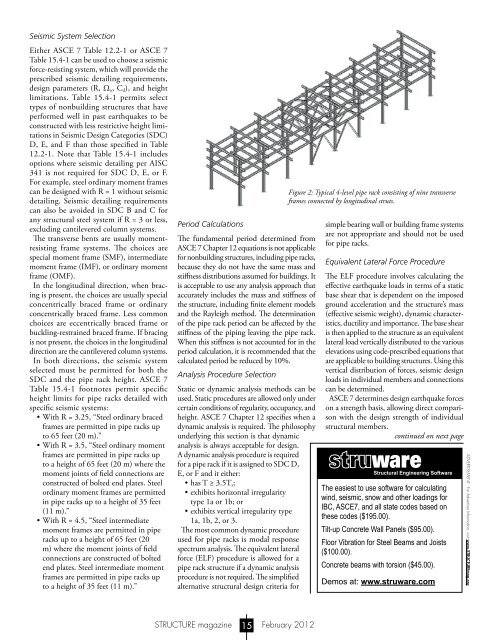
Figure 2: Typical 4-level pipe rack consisting of nine transverse<br />
frames connected by longitudinal struts.<br />
simple bearing wall or building frame systems<br />
are not appropriate and should not be used<br />
for pipe racks.<br />
Equivalent Lateral Force Procedure<br />
The ELF procedure involves calculating the<br />
effective earthquake loads in terms of a static<br />
base shear that is dependent on the imposed<br />
ground acceleration and the structure’s mass<br />
(effective seismic weight), dynamic characteristics,<br />
ductility and importance. The base shear<br />
is then applied to the structure as an equivalent<br />
lateral load vertically distributed to the various<br />
elevations using code-prescribed equations that<br />
are applicable to building structures. Using this<br />
vertical distribution of forces, seismic design<br />
loads in individual members and connections<br />
can be determined.<br />
ASCE 7 determines design earthquake forces<br />
on a strength basis, allowing direct comparison<br />
with the design strength of individual<br />
structural members.<br />
continued on next page<br />
The easiest to use software for calculating<br />
wind, seismic, snow and other loadings for<br />
IBC, ASCE7, and all state codes based on<br />
these codes ($195.00).<br />
Tilt-up Concrete Wall Panels ($95.00).<br />
Floor Vibration for Steel Beams and Joists<br />
($100.00).<br />
Concrete beams with torsion ($45.00).<br />
Demos at: www.struware.com<br />
ADVERTISEMENT - For Advertiser Information, visit www.STRUCTUREmag.org<br />
STRUCTURE magazine 15 February 2012