Read Article - CB&I
Read Article - CB&I
Read Article - CB&I

Create successful ePaper yourself
Turn your PDF publications into a flip-book with our unique Google optimized e-Paper software.
Structural<br />
Performance<br />
performance issues relative<br />
to extreme events<br />
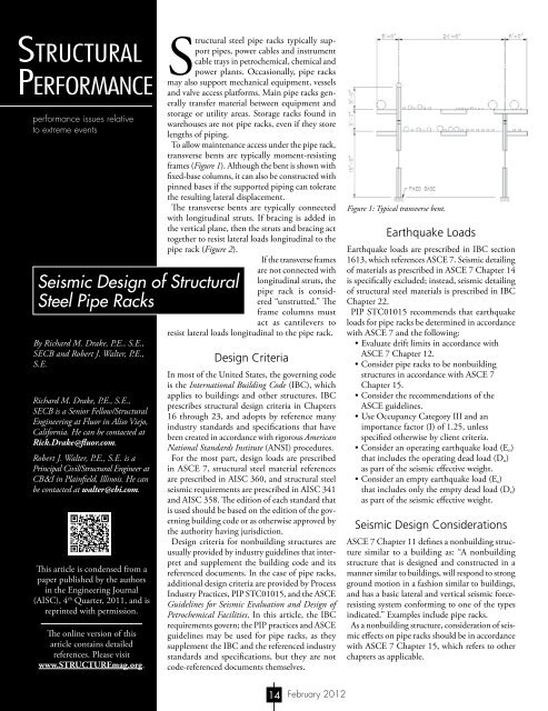
Seismic Design of Structural<br />
Steel Pipe Racks<br />
By Richard M. Drake, P.E., S.E.,<br />
SECB and Robert J. Walter, P.E.,<br />
S.E.<br />
Richard M. Drake, P.E., S.E.,<br />
SECB is a Senior Fellow/Structural<br />
Engineering at Fluor in Aliso Viejo,<br />
California. He can be contacted at<br />
Rick.Drake@fluor.com.<br />
Robert J. Walter, P.E., S.E. is a<br />
Principal Civil/Structural Engineer at<br />
CB&I in Plainfield, Illinois. He can<br />
be contacted at walter@cbi.com.<br />
This article is condensed from a<br />
paper published by the authors<br />
in the Engineering Journal<br />
(AISC), 4 th Quarter, 2011, and is<br />
reprinted with permission.<br />
The online version of this<br />
article contains detailed<br />
references. Please visit<br />
www.STRUCTUREmag.org.<br />
Structural steel pipe racks typically support<br />
pipes, power cables and instrument<br />
cable trays in petrochemical, chemical and<br />
power plants. Occasionally, pipe racks<br />
may also support mechanical equipment, vessels<br />
and valve access platforms. Main pipe racks generally<br />
transfer material between equipment and<br />
storage or utility areas. Storage racks found in<br />
warehouses are not pipe racks, even if they store<br />
lengths of piping.<br />
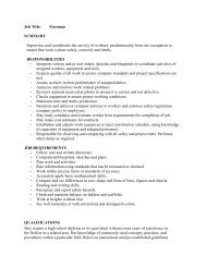
To allow maintenance access under the pipe rack,<br />
transverse bents are typically moment-resisting<br />
frames (Figure 1). Although the bent is shown with<br />
fixed-base columns, it can also be constructed with<br />
pinned bases if the supported piping can tolerate<br />
the resulting lateral displacement.<br />
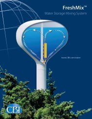
The transverse bents are typically connected<br />
with longitudinal struts. If bracing is added in<br />
the vertical plane, then the struts and bracing act<br />
together to resist lateral loads longitudinal to the<br />
pipe rack (Figure 2).<br />
If the transverse frames<br />
are not connected with<br />
longitudinal struts, the<br />
pipe rack is considered<br />
“unstrutted.” The<br />
frame columns must<br />
act as cantilevers to<br />
resist lateral loads longitudinal to the pipe rack.<br />
Design Criteria<br />
In most of the United States, the governing code<br />
is the International Building Code (IBC), which<br />
applies to buildings and other structures. IBC<br />
prescribes structural design criteria in Chapters<br />
16 through 23, and adopts by reference many<br />
industry standards and specifications that have<br />
been created in accordance with rigorous American<br />
National Standards Institute (ANSI) procedures.<br />
For the most part, design loads are prescribed<br />
in ASCE 7, structural steel material references<br />
are prescribed in AISC 360, and structural steel<br />
seismic requirements are prescribed in AISC 341<br />
and AISC 358. The edition of each standard that<br />
is used should be based on the edition of the governing<br />
building code or as otherwise approved by<br />
the authority having jurisdiction.<br />
Design criteria for nonbuilding structures are<br />
usually provided by industry guidelines that interpret<br />
and supplement the building code and its<br />
referenced documents. In the case of pipe racks,<br />
additional design criteria are provided by Process<br />
Industry Practices, PIP STC01015, and the ASCE<br />
Guidelines for Seismic Evaluation and Design of<br />
Petrochemical Facilities. In this article, the IBC<br />
requirements govern; the PIP practices and ASCE<br />
guidelines may be used for pipe racks, as they<br />
supplement the IBC and the referenced industry<br />
standards and specifications, but they are not<br />
code-referenced documents themselves.<br />
Figure 1: Typical transverse bent.<br />
Earthquake Loads<br />
Earthquake loads are prescribed in IBC section<br />
1613, which references ASCE 7. Seismic detailing<br />
of materials as prescribed in ASCE 7 Chapter 14<br />
is specifically excluded; instead, seismic detailing<br />
of structural steel materials is prescribed in IBC<br />
Chapter 22.<br />
PIP STC01015 recommends that earthquake<br />
loads for pipe racks be determined in accordance<br />
with ASCE 7 and the following:<br />
• Evaluate drift limits in accordance with<br />
ASCE 7 Chapter 12.<br />
• Consider pipe racks to be nonbuilding<br />
structures in accordance with ASCE 7<br />
Chapter 15.<br />
• Consider the recommendations of the<br />
ASCE guidelines.<br />
• Use Occupancy Category III and an<br />
importance factor (I) of 1.25, unless<br />
specified otherwise by client criteria.<br />
• Consider an operating earthquake load (E o )<br />
that includes the operating dead load (D o )<br />
as part of the seismic effective weight.<br />
• Consider an empty earthquake load (E e )<br />
that includes only the empty dead load (D e )<br />
as part of the seismic effective weight.<br />
Seismic Design Considerations<br />
ASCE 7 Chapter 11 defines a nonbuilding structure<br />
similar to a building as: “A nonbuilding<br />
structure that is designed and constructed in a<br />
manner similar to buildings, will respond to strong<br />
ground motion in a fashion similar to buildings,<br />
and has a basic lateral and vertical seismic forceresisting<br />
system conforming to one of the types<br />
indicated.” Examples include pipe racks.<br />
As a nonbuilding structure, consideration of seismic<br />
effects on pipe racks should be in accordance<br />
with ASCE 7 Chapter 15, which refers to other<br />
chapters as applicable.<br />
14<br />
February 2012
Seismic System Selection<br />
Either ASCE 7 Table 12.2-1 or ASCE 7<br />
Table 15.4-1 can be used to choose a seismic<br />
force-resisting system, which will provide the<br />
prescribed seismic detailing requirements,<br />
design parameters (R, Ω o , C d ), and height<br />
limitations. Table 15.4-1 permits select<br />
types of nonbuilding structures that have<br />
performed well in past earthquakes to be<br />
constructed with less restrictive height limitations<br />
in Seismic Design Categories (SDC)<br />
D, E, and F than those specified in Table<br />
12.2-1. Note that Table 15.4-1 includes<br />
options where seismic detailing per AISC<br />
341 is not required for SDC D, E, or F.<br />
For example, steel ordinary moment frames<br />
can be designed with R = 1 without seismic<br />
detailing. Seismic detailing requirements<br />
can also be avoided in SDC B and C for<br />
any structural steel system if R = 3 or less,<br />
excluding cantilevered column systems.<br />
The transverse bents are usually momentresisting<br />
frame systems. The choices are<br />
special moment frame (SMF), intermediate<br />
moment frame (IMF), or ordinary moment<br />
frame (OMF).<br />
In the longitudinal direction, when bracing<br />
is present, the choices are usually special<br />
concentrically braced frame or ordinary<br />
concentrically braced frame. Less common<br />
choices are eccentrically braced frame or<br />
buckling-restrained braced frame. If bracing<br />
is not present, the choices in the longitudinal<br />
direction are the cantilevered column systems.<br />
In both directions, the seismic system<br />
selected must be permitted for both the<br />
SDC and the pipe rack height. ASCE 7<br />
Table 15.4-1 footnotes permit specific<br />
height limits for pipe racks detailed with<br />
specific seismic systems:<br />
• With R = 3.25, “Steel ordinary braced<br />
frames are permitted in pipe racks up<br />
to 65 feet (20 m).”<br />
• With R = 3.5, “Steel ordinary moment<br />
frames are permitted in pipe racks up<br />
to a height of 65 feet (20 m) where the<br />
moment joints of field connections are<br />
constructed of bolted end plates. Steel<br />
ordinary moment frames are permitted<br />
in pipe racks up to a height of 35 feet<br />
(11 m).”<br />
• With R = 4.5, “Steel intermediate<br />
moment frames are permitted in pipe<br />
racks up to a height of 65 feet (20<br />
m) where the moment joints of field<br />
connections are constructed of bolted<br />
end plates. Steel intermediate moment<br />
frames are permitted in pipe racks up<br />
to a height of 35 feet (11 m).”<br />
Period Calculations<br />
The fundamental period determined from<br />
ASCE 7 Chapter 12 equations is not applicable<br />
for nonbuilding structures, including pipe racks,<br />
because they do not have the same mass and<br />
stiffness distributions assumed for buildings. It<br />
is acceptable to use any analysis approach that<br />
accurately includes the mass and stiffness of<br />
the structure, including finite element models<br />
and the Rayleigh method. The determination<br />
of the pipe rack period can be affected by the<br />
stiffness of the piping leaving the pipe rack.<br />
When this stiffness is not accounted for in the<br />
period calculation, it is recommended that the<br />
calculated period be reduced by 10%.<br />
Analysis Procedure Selection<br />
Static or dynamic analysis methods can be<br />
used. Static procedures are allowed only under<br />
certain conditions of regularity, occupancy, and<br />
height. ASCE 7 Chapter 12 specifies when a<br />
dynamic analysis is required. The philosophy<br />
underlying this section is that dynamic<br />
analysis is always acceptable for design.<br />
A dynamic analysis procedure is required<br />
for a pipe rack if it is assigned to SDC D,<br />
E, or F and it either:<br />
• has T ≥ 3.5T s ;<br />
• exhibits horizontal irregularity<br />
type 1a or 1b; or<br />
• exhibits vertical irregularity type<br />
1a, 1b, 2, or 3.<br />
The most common dynamic procedure<br />
used for pipe racks is modal response<br />
spectrum analysis. The equivalent lateral<br />
force (ELF) procedure is allowed for a<br />
pipe rack structure if a dynamic analysis<br />
procedure is not required. The simplified<br />
alternative structural design criteria for<br />
Figure 2: Typical 4-level pipe rack consisting of nine transverse<br />
frames connected by longitudinal struts.<br />
simple bearing wall or building frame systems<br />
are not appropriate and should not be used<br />
for pipe racks.<br />
Equivalent Lateral Force Procedure<br />
The ELF procedure involves calculating the<br />
effective earthquake loads in terms of a static<br />
base shear that is dependent on the imposed<br />
ground acceleration and the structure’s mass<br />
(effective seismic weight), dynamic characteristics,<br />
ductility and importance. The base shear<br />
is then applied to the structure as an equivalent<br />
lateral load vertically distributed to the various<br />
elevations using code-prescribed equations that<br />
are applicable to building structures. Using this<br />
vertical distribution of forces, seismic design<br />
loads in individual members and connections<br />
can be determined.<br />
ASCE 7 determines design earthquake forces<br />
on a strength basis, allowing direct comparison<br />
with the design strength of individual<br />
structural members.<br />
continued on next page<br />
The easiest to use software for calculating<br />
wind, seismic, snow and other loadings for<br />
IBC, ASCE7, and all state codes based on<br />
these codes ($195.00).<br />
Tilt-up Concrete Wall Panels ($95.00).<br />
Floor Vibration for Steel Beams and Joists<br />
($100.00).<br />
Concrete beams with torsion ($45.00).<br />
Demos at: www.struware.com<br />
ADVERTISEMENT - For Advertiser Information, visit www.STRUCTUREmag.org<br />
STRUCTURE magazine 15 February 2012
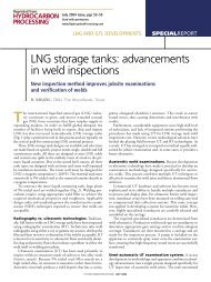
Figure 3: AISC 358 extended end plate connections.<br />
Modal Response Spectrum Analysis<br />
MRSA is acceptable for the analysis of pipe<br />
racks, and may be required if certain plan and/<br />
or vertical irregularities are identified. The basis<br />
of MRSA is that the pipe rack’s mass (effective<br />
seismic weight) and stiffness are carefully modeled,<br />
allowing the dynamic analysis of multiple<br />
vibration modes that result in an accurate distribution<br />
of the base shear forces throughout<br />
the structure. The MRSA must include a sufficient<br />
number of modes in order to achieve a<br />
minimum of 90% mass participation.<br />
Two MRSA runs are typically required for<br />
pipe racks. The first run includes the operating<br />
dead load (D o ) as the seismic effective weight<br />
to determine the operating earthquake load<br />
(E o ). The second run includes the empty dead<br />
load (D e ) as the seismic effective weight to<br />
determine the empty earthquake load (E e ).<br />
The MRSA input ground motion parameters<br />
(S DS , S D1 ) are used to define the ASCE<br />
7 elastic design response spectrum. To obtain<br />
“static force levels,” the MRSA force results<br />
must be divided by the quantity (R/I). ASCE<br />
7 does not allow an engineer to scale down<br />
MRSA force levels to ELF force levels because<br />
the ELF procedure may result in an underprediction<br />
of response for structures with<br />
significant higher-mode participation. On<br />
the other hand, when the MRSA base shear<br />
is less than 85% of the ELF base shear, the<br />
MRSA results must be scaled up to no less<br />
than 85% of the ELF values. This lower limit<br />
on the design base shear is imposed to account<br />
for higher mode effects, and to ensure that the<br />
design forces are not underestimated through<br />
the use of a structural model that does not<br />
accurately represent the mass and stiffness<br />
characteristics of the pipe rack.<br />
Drift<br />
To obtain amplified seismic displacements,<br />
the displacement results calculated from the<br />
elastic analysis must be multiplied by the<br />
quantity (C d /I e ) to account for the expected<br />
inelastic deformations when checking<br />
against the drift limits of ASCE 7 Table<br />
12.12-1. The displacement results must<br />
be multiplied by C d for checking pipe flexibility<br />
and structure separation.<br />
It is important that the drift of pipe racks<br />
be compared to other adjacent structures<br />
where piping and cable trays run. The piping<br />
and cable trays must be flexible enough to<br />
accommodate the movements of the pipe<br />
rack relative to these structures.<br />
Seismic Detailing Requirements<br />
The selection of a seismic force-resisting<br />
system from ASCE 7 Table 12.2-1 dictates<br />
detailing requirements prescribed in ASCE<br />
7 Chapter 14. Because this chapter is specifically<br />
excluded by the IBC, seismic detailing<br />
requirements for structural steel systems must<br />
be taken instead from IBC Chapter 22 and<br />
AISC 341. The selection of a seismic forceresisting<br />
system from ASCE 7 Table 15.4-1<br />
directly dictates seismic detailing requirements<br />
prescribed in AISC 341.<br />
AISC 341 includes such requirements for each<br />
structural steel system listed in the two ASCE 7<br />
tables. In general, there is a relationship between<br />
R values and seismic detailing requirements.<br />
Lower R values and higher earthquake design<br />
forces are accompanied by minimal seismic<br />
detailing requirements. Higher R values and<br />
lower earthquake design forces are accompanied<br />
by more restrictive seismic detailing requirements<br />
to provide greater ductility.<br />
AISC 341 prescribes that beams in OMF<br />
systems do not require lateral bracing beyond<br />
those requirements prescribed in AISC 360.<br />
However, beams in IMF and SMF systems<br />
have progressively more restrictive requirements<br />
for lateral bracing of beams that can<br />
only be met by the addition of a horizontal<br />
bracing system at each pipe level. For this<br />
reason, it may be more economical to select<br />
an OMF system for the transverse bents.<br />
AISC 341 prescribes that beam-tocolumn<br />
connections for IMF and SMF<br />
systems be based on laboratory testing.<br />
OMF beam-to-column connections may<br />
be either calculated to match the expected<br />
plastic moment strength of the beam or<br />
based on laboratory testing. AISC 358<br />
prescribes specific requirements for laboratory-tested<br />
systems appropriate for use in<br />
seismic moment frames. One of the systems<br />
included in AISC 358 is the bolted endplate<br />
moment connection, commonly used<br />
in pipe rack construction (Figure 3). These<br />
connections are popular in industrial plants<br />
because they involve no field welding.<br />
Redundancy in SDC A, B, or C<br />
In accordance with ASCE 7, for all structures,<br />
ρ = 1.0.<br />
Redundancy in SDC D, E, or F<br />
The typical pipe rack has no horizontal bracing<br />
system that serves as a diaphragm. If one<br />
individual bent fails, there is no load path for<br />
lateral force transfer to the adjacent frame.<br />
As a result, the pipe rack must be treated as<br />
a non-redundant structure.<br />
• For a transverse bent to qualify for ρ =<br />
1.0, it must have four or more columns<br />
and three or more bays at each level.<br />
This ensures that the loss of moment<br />
resistance at both ends of a single beam<br />
does not result in more than a 33% loss<br />
of story strength. Otherwise, ρ = 1.3.<br />
• For an individual longitudinal braced<br />
frame to qualify for ρ = 1.0, it must<br />
have two or more bays of chevron or X<br />
bracing (or four individual braces) at each<br />
level on each frame line. This ensures<br />
that the loss of an individual brace or<br />
connection does not result in more than<br />
a 33% loss of story strength nor cause an<br />
extreme torsional irregularity (Type 1b).<br />
Otherwise, ρ = 1.3.<br />
If the pipe rack is provided with a horizontal<br />
bracing system that serves as a diaphragm and<br />
provides a load path for lateral transfer, it can<br />
be treated as a redundant structure.<br />
• For a pipe rack to qualify in the<br />
transverse direction for ρ = 1.0, it needs<br />
to have horizontal bracing between all<br />
transverse bents and a minimum of four<br />
transverse bents. Otherwise, ρ = 1.3.<br />
• For a pipe rack to qualify in the<br />
longitudinal direction for ρ = 1.0, there<br />
needs to be a minimum of four transverse<br />
bents, and each longitudinal frame line<br />
needs to have two or more individual<br />
braces at each level. Otherwise, ρ = 1.3.▪<br />
STRUCTURE magazine 16 February 2012