Guide for the Development of Bicycle Facilities - The Industrialized ...
Guide for the Development of Bicycle Facilities - The Industrialized ...
Guide for the Development of Bicycle Facilities - The Industrialized ...

You also want an ePaper? Increase the reach of your titles
YUMPU automatically turns print PDFs into web optimized ePapers that Google loves.
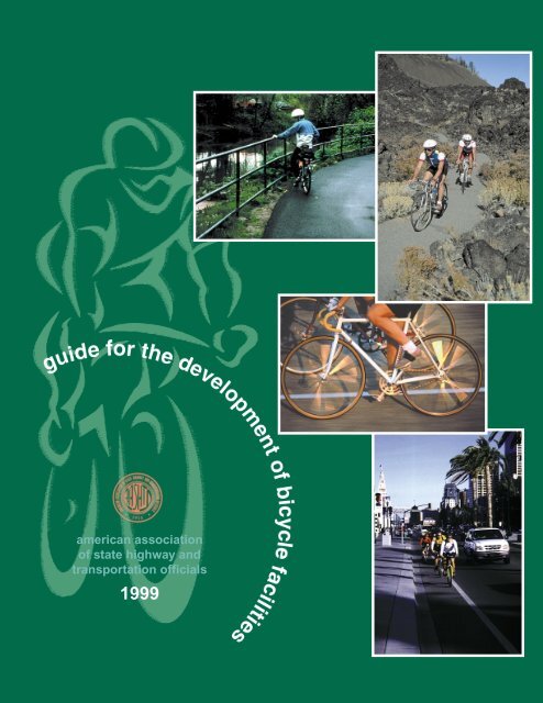
american association<br />
<strong>of</strong> state highway and<br />
transportation <strong>of</strong>ficials<br />
1999
guide<br />
<strong>for</strong> <strong>the</strong> development <strong>of</strong> bicycle<br />
american association <strong>of</strong><br />
state highway and<br />
transportation <strong>of</strong>ficials<br />
444 north capitol street, nw<br />
washington, dc 20001<br />
(202) 624-5800 (tel)<br />
(202) 624-5806 (fax)<br />
www.aashto.org<br />
facilities<br />
1999<br />
prepared by <strong>the</strong> aashto task <strong>for</strong>ce on geometric design
© Copyright 1999 by <strong>the</strong> American Association <strong>of</strong> State Highway and Transportation Officials.<br />
All Rights Reserved. Printed in <strong>the</strong> United States <strong>of</strong> America. This book, or parts <strong>the</strong>re<strong>of</strong>, may not<br />
be reproduced in any <strong>for</strong>m without permission <strong>of</strong> <strong>the</strong> publishers.<br />
Printed in <strong>the</strong> United States <strong>of</strong> America.<br />
ISBN: 1-56051-102-8
AASHTO EXECUTIVE COMMITTEE<br />
1999<br />
President<br />
DAN FLOWERS, Arkansas<br />
Vice President<br />
THOMAS R. WARNE, Utah<br />
Secretary-Treasurer<br />
CLYDE E. PYERS, Maryland<br />
Elected Regional Representatives<br />
Region I<br />
GLENN GERSHANECK, Vermont<br />
JAMES SULLIVAN, Connecticut<br />
Region II<br />
ELIZABETH S. MABRY, South Carolina<br />
KAM K. MOVASSAGHI, Louisiana<br />
Region III<br />
GORDON PROCTOR, Ohio<br />
JAMES C. CODELL, III, Kentucky<br />
Region IV<br />
DWIGHT BOWER, Idaho<br />
SID MORRISON, Washington<br />
Executive Director, Ex Officio<br />
JOHN HORSLEY, Washington, D.C.
TASK FORCE ON GEOMETRIC DESIGN<br />
Robert L. Walters, Chairman<br />
William Prosser, Secretary<br />
Region 1<br />
New Hampshire<br />
New Jersey<br />
New York<br />
Port Authority <strong>of</strong> NY & NJ<br />
FHWA<br />
Region 2<br />
Alabama<br />
Arkansas<br />
Kentucky<br />
Mississippi<br />
West Virginia<br />
Region 3<br />
Illinois<br />
Kansas<br />
Nebraska<br />
Ohio<br />
Region 4<br />
Arizona<br />
Cali<strong>for</strong>nia<br />
New Mexico<br />
Nevada<br />
Texas<br />
Wyoming<br />
Donald A. Lytord<br />
Charles A. Goessel<br />
Philip J. Clark<br />
Robert P. Parisi<br />
William Prosser, Secretary<br />
Don T. Arkle<br />
Robert L. Walters, Chair<br />
John Sacksteder<br />
John Pickering<br />
Norman H. Roush<br />
Ken Lazar<br />
James O. Brewer<br />
Ted Watson<br />
Larry Su<strong>the</strong>rland<br />
Terry Otterness<br />
Jerry Champa<br />
Charlie V. Trujillo<br />
Steve R. Oxoby<br />
Mark A. Marek<br />
Paul Bercich<br />
American Public Works Association<br />
National Association <strong>of</strong> County Engineers<br />
National League <strong>of</strong> Cities<br />
John N. LaPlante<br />
Dennis A. Grylicki<br />
Harold E. Bastin
HIGHWAY SUBCOMMITTEE ON DESIGN<br />
1999<br />
KENNETH I. WARREN, Mississippi, Chairman<br />
JAMES F. BYRNES, JR., CONNECTICUT, Vice Chairman<br />
HENRY H. RENTZ, FHWA, Secretary<br />
ALABAMA, Don T. Arkle, Steven E. Walker<br />
ALASKA, Mike Downing<br />
ARIZONA, John L. Louis<br />
ARKANSAS, Dale F. Loe, Phillip L. McConnell<br />
CALIFORNIA, Alan Glen<br />
COLORADO, Timothy J. Harris<br />
CONNECTICUT, Carl F. Bard, James F. Byrnes, Jr., Bradley J. Smith<br />
DELAWARE, Michael A. Angelo, Joseph M. Satterfield, Jr., Michael H. Simmons<br />
DISTRICT OF COLUMBIA, San<strong>for</strong>d H. Vinick<br />
FLORIDA, Billy Hattaway, Jim Mills, Freddie L. Simmons<br />
GEORGIA, James Kennerly, Joseph Palladi, Walker W. Scott<br />
HAWAII, Larry Leopardi<br />
IDAHO, Steven Hutchinson<br />
ILLINOIS, William T. Sunley<br />
INDIANA, Phelps H. Klika<br />
IOWA, Jay L. Chiglo, Donald L. East, David L. Little<br />
KANSAS, Richard G. Adams, James O. Brewer<br />
KENTUCKY, David Kratt, Charles S. Raymer, John Sacksteder<br />
LOUISIANA, N. Kent Israel, Nick Kalivado, III, Lloyd “Buddy” Porta<br />
MAINE, Michael E. Burns<br />
MARYLAND, Robert Douglass, Kirk G. McClelland<br />
MASSACHUSETTS, John Blundo, Stanley Wood, Jr.<br />
MICHIGAN, Paul F. Miller<br />
MINNESOTA, Delbert “Del” Gerdes<br />
MISSISSIPPI, John Pickering, Wendel T. Ruff, Kenneth I. Warren<br />
MISSOURI, Humbert Sfreddo, J.T. Bill Yarnell, Jr.<br />
MONTANA, Ronald E. Williams<br />
NEBRASKA, Eldon D. Poppe<br />
NEVADA, Susan Martinovich, Steve R. Oxoby<br />
NEW HAMPSHIRE, Craig A. Green<br />
NEW JERSEY, Richard W. Dunne, Arthur J. Eisdorfer, Charles Goessel, Charles Miller<br />
NEW MEXICO, Roy Maestas<br />
NEW YORK, Peter J. Bellair, Philip J. Clark, Robert A. Dennison<br />
NORTH CAROLINA, Len Hill, Don R. Morton, G.T. (Tom) Shearin<br />
NORTH DAKOTA, Ken Birst
OHIO, Larry J. Shannon<br />
OKLAHOMA, Christine M. Senkowski, Bruce E. Taylor<br />
OREGON, Jeff Scheick<br />
PENNSYLVANIA, Mahendra G. Patel, Dean A. Schreiber<br />
RHODE ISLAND, J. Michael Bennett<br />
SOUTH CAROLINA, William M. Dubose, III, Rocque Kneece, Robert I. Pratt<br />
SOUTH DAKOTA, Timothy Bjorneberg, Larry Engbrecht<br />
TENNESSEE, James P. Alexander, Harris Scott, Jim Zeigler<br />
TEXAS, Robert Wilson<br />
U.S. DOT, Henry H. Rentz (FHWA), John Rice (FAA)<br />
UTAH, P.K. Mohanty<br />
VERMONT, Donald H. Lathrop, Robert F. Shattuck<br />
VIRGINIA, James T. Harris, Jimmy Mills, Mohammed Mirshahi<br />
WASHINGTON, Richard Albin, Brian J. Ziegler<br />
WEST VIRGINIA, David E. Clevenger, Randolph Epperly, Jr., Norman H. Roush<br />
WISCONSIN, John E. Haverberg, Robert F. Pfeiffer<br />
WYOMING, Paul Bercich<br />
AFFILIATE MEMBERS<br />
Alberta, Alan Kwan<br />
British Columbia, Merv Clark<br />
Mariana Islands, Edward M. Deleon Guerrero<br />
New Brunswick, C. Herbert Page<br />
Newfoundland, Terry McCarthy<br />
Northwest Territories, Peter Vician<br />
Ontario, Joseph A. Bucik<br />
Saskatchewan, Ted Stobbs<br />
ASSOCIATE MEMBERS-STATE<br />
Port Authority <strong>of</strong> NY & NJ, J. Lawrence Williams<br />
ASSOCIATE MEMBERS-FEDERAL<br />
U.S. Department <strong>of</strong> Agriculture–Forest Service, Richard Sowa<br />
AASHTO Staff Liaison, Ken Kobetsky
Table <strong>of</strong> Contents<br />
Table <strong>of</strong> Contents<br />
INTRODUCTION . . . . . . . . . . . . . . . . . . . . . . . . . . . . . . . . . . . . . . . . . . . . . . . . . . . 1<br />
Purpose . . . . . . . . . . . . . . . . . . . . . . . . . . . . . . . . . . . . . . . . . . . . . . . . . . . . . 1<br />
Scope . . . . . . . . . . . . . . . . . . . . . . . . . . . . . . . . . . . . . . . . . . . . . . . . . . . . . . 2<br />
Definitions . . . . . . . . . . . . . . . . . . . . . . . . . . . . . . . . . . . . . . . . . . . . . . . . . . 2<br />
Chapter 1 PLANNING . . . . . . . . . . . . . . . . . . . . . . . . . . . . . . . . . . . . . . . . . . . . . . . 5<br />
<strong>The</strong> <strong>Bicycle</strong> . . . . . . . . . . . . . . . . . . . . . . . . . . . . . . . . . . . . . . . . . . . . . . . . . 5<br />
<strong>The</strong> <strong>Bicycle</strong> User . . . . . . . . . . . . . . . . . . . . . . . . . . . . . . . . . . . . . . . . . . . . . 5<br />
Choosing <strong>the</strong> Appropriate Facility Type . . . . . . . . . . . . . . . . . . . . . . . . . . . . 6<br />
Types <strong>of</strong> <strong>Bicycle</strong> <strong>Facilities</strong> . . . . . . . . . . . . . . . . . . . . . . . . . . . . . . . . . . . . . . 7<br />
Inventory <strong>of</strong> Existing Conditions . . . . . . . . . . . . . . . . . . . . . . . . . . . . . . . . . . 9<br />
Plans <strong>for</strong> Improvements . . . . . . . . . . . . . . . . . . . . . . . . . . . . . . . . . . . . . . . 10<br />
Selection <strong>of</strong> a <strong>Bicycle</strong> Facility . . . . . . . . . . . . . . . . . . . . . . . . . . . . . . . . . . . 10<br />
Education Programs <strong>for</strong> Bicyclists and Motorists . . . . . . . . . . . . . . . . . . . . . 13<br />
Chapter 2 DESIGN . . . . . . . . . . . . . . . . . . . . . . . . . . . . . . . . . . . . . . . . . . . . . . . . . 15<br />
Shared Roadways. . . . . . . . . . . . . . . . . . . . . . . . . . . . . . . . . . . . . . . . . . . . . . . . . . . 16<br />
Paved Shoulders . . . . . . . . . . . . . . . . . . . . . . . . . . . . . . . . . . . . . . . . . . . . . 16<br />
Increased Lane Width . . . . . . . . . . . . . . . . . . . . . . . . . . . . . . . . . . . . . . . . . 17<br />
On-Street Parking . . . . . . . . . . . . . . . . . . . . . . . . . . . . . . . . . . . . . . . . . . . . 17<br />
Pavement Surface Quality . . . . . . . . . . . . . . . . . . . . . . . . . . . . . . . . . . . . . 18<br />
Drainage Inlet Grates . . . . . . . . . . . . . . . . . . . . . . . . . . . . . . . . . . . . . . . . . 18<br />
Signed Shared Roadways . . . . . . . . . . . . . . . . . . . . . . . . . . . . . . . . . . . . . . . . . . . . . 19<br />
Designating Sidewalks as Signed Bikeways . . . . . . . . . . . . . . . . . . . . . . . . 20<br />
Signing <strong>of</strong> Shared Roadways . . . . . . . . . . . . . . . . . . . . . . . . . . . . . . . . . . . . 20<br />
Table <strong>of</strong> Contents
Bike Lanes . . . . . . . . . . . . . . . . . . . . . . . . . . . . . . . . . . . . . . . . . . . . . . . . . . . . . . . . 22<br />
Bike Lane Widths . . . . . . . . . . . . . . . . . . . . . . . . . . . . . . . . . . . . . . . . . . . . 22<br />
Bike Lanes at Intersections . . . . . . . . . . . . . . . . . . . . . . . . . . . . . . . . . . . . . 25<br />
Bike Lanes and Turning Lanes . . . . . . . . . . . . . . . . . . . . . . . . . . . . . . . . . . 25<br />
Bike Lane Symbol <strong>Guide</strong>lines . . . . . . . . . . . . . . . . . . . . . . . . . . . . . . . . . . . 31<br />
Shared Use Paths . . . . . . . . . . . . . . . . . . . . . . . . . . . . . . . . . . . . . . . . . . . . . . . . . . . 33<br />
Separation Between Shared Use Paths and Roadways . . . . . . . . . . . . . . . . 33<br />
Width and Clearance . . . . . . . . . . . . . . . . . . . . . . . . . . . . . . . . . . . . . . . . . 35<br />
Design Speed . . . . . . . . . . . . . . . . . . . . . . . . . . . . . . . . . . . . . . . . . . . . . . . 36<br />
Horizontal Alignment . . . . . . . . . . . . . . . . . . . . . . . . . . . . . . . . . . . . . . . . . 37<br />
Grade . . . . . . . . . . . . . . . . . . . . . . . . . . . . . . . . . . . . . . . . . . . . . . . . . . . . . 39<br />
Sight Distance . . . . . . . . . . . . . . . . . . . . . . . . . . . . . . . . . . . . . . . . . . . . . . 40<br />
Path Roadway Intersections . . . . . . . . . . . . . . . . . . . . . . . . . . . . . . . . . . . . 46<br />
O<strong>the</strong>r Intersection Design Issues . . . . . . . . . . . . . . . . . . . . . . . . . . . . . . . . . 50<br />
Signing and Marking . . . . . . . . . . . . . . . . . . . . . . . . . . . . . . . . . . . . . . . . . 53<br />
Pavement Structure . . . . . . . . . . . . . . . . . . . . . . . . . . . . . . . . . . . . . . . . . . . 54<br />
Structures . . . . . . . . . . . . . . . . . . . . . . . . . . . . . . . . . . . . . . . . . . . . . . . . . . 55<br />
Drainage . . . . . . . . . . . . . . . . . . . . . . . . . . . . . . . . . . . . . . . . . . . . . . . . . . . 56<br />
Lighting . . . . . . . . . . . . . . . . . . . . . . . . . . . . . . . . . . . . . . . . . . . . . . . . . . . . 57<br />
Restriction <strong>of</strong> Motor Vehicle Traffic . . . . . . . . . . . . . . . . . . . . . . . . . . . . . . . 57<br />
Undesirability <strong>of</strong> Sidewalks as Shared Use Paths . . . . . . . . . . . . . . . . . . . . . 58<br />
Shared Use with Motorbikes, Horses and Snowmobiles . . . . . . . . . . . . . . . 58<br />
O<strong>the</strong>r Design Considerations . . . . . . . . . . . . . . . . . . . . . . . . . . . . . . . . . . . . . . . . . . 60<br />
Railroad Crossings. . . . . . . . . . . . . . . . . . . . . . . . . . . . . . . . . . . . . . . . . . . . 60<br />
<strong>Bicycle</strong>s on Freeways . . . . . . . . . . . . . . . . . . . . . . . . . . . . . . . . . . . . . . . . . 60<br />
<strong>Bicycle</strong> <strong>Facilities</strong> through Interchange Areas . . . . . . . . . . . . . . . . . . . . . . . . 62<br />
<strong>Bicycle</strong>s at Modern Roundabouts . . . . . . . . . . . . . . . . . . . . . . . . . . . . . . . . 64<br />
Table <strong>of</strong> Contents
Traffic Signals . . . . . . . . . . . . . . . . . . . . . . . . . . . . . . . . . . . . . . . . . . . . . . . 64<br />
Obstruction Markings . . . . . . . . . . . . . . . . . . . . . . . . . . . . . . . . . . . . . . . . . 67<br />
<strong>Bicycle</strong> Parking <strong>Facilities</strong>. . . . . . . . . . . . . . . . . . . . . . . . . . . . . . . . . . . . . . . 67<br />
Additional <strong>Bicycle</strong> Amenities . . . . . . . . . . . . . . . . . . . . . . . . . . . . . . . . . . . 68<br />
Accessibility Requirements . . . . . . . . . . . . . . . . . . . . . . . . . . . . . . . . . . . . . 69<br />
Chapter 3 OPERATION AND MAINTENANCE. . . . . . . . . . . . . . . . . . . . . . . . . . . . 73<br />
APPENDIX . . . . . . . . . . . . . . . . . . . . . . . . . . . . . . . . . . . . . . . . . . . . . . . . . . . . . . . . 75<br />
Review <strong>of</strong> Legal Status. . . . . . . . . . . . . . . . . . . . . . . . . . . . . . . . . . . . . . . . . 75<br />
REFERENCES . . . . . . . . . . . . . . . . . . . . . . . . . . . . . . . . . . . . . . . . . . . . . . . . . . . . . . 77<br />
Table <strong>of</strong> Contents
guide <strong>for</strong> <strong>the</strong> development <strong>of</strong> bicycle facilities 1<br />
Introduction<br />
Introduction<br />
<strong>Bicycle</strong> travel has played an historic role in transportation. Even be<strong>for</strong>e<br />
<strong>the</strong> invention <strong>of</strong> <strong>the</strong> automobile, <strong>the</strong> League <strong>of</strong> American Wheelmen promoted<br />
improved traveled ways.<br />
Increasingly, transportation <strong>of</strong>ficials throughout <strong>the</strong> United States are<br />
recognizing <strong>the</strong> bicycle as a viable transportation mode. While recreational<br />
cycling is still <strong>the</strong> primary use <strong>of</strong> bicycles in this country, <strong>the</strong><br />
number <strong>of</strong> people using bicycles <strong>for</strong> commuting and o<strong>the</strong>r travel purposes<br />
has been increasing since <strong>the</strong> early 1970s. Nationwide, people are<br />
recognizing <strong>the</strong> energy efficiency, cost effectiveness, health benefits and<br />
environmental advantages <strong>of</strong> bicycling.<br />
Local, state and federal agencies are responding to <strong>the</strong> increased use <strong>of</strong><br />
bicycles by implementing a wide variety <strong>of</strong> bicycle-related projects and<br />
programs. <strong>The</strong> emphasis now being placed on bicycle transportation requires<br />
an understanding <strong>of</strong> bicycles, bicyclists and bicycle facilities. This<br />
manual addresses <strong>the</strong>se issues and clarifies <strong>the</strong> elements needed to make<br />
bicycling a viable transportation alternative.<br />
All highways, except those where cyclists are legally prohibited, should<br />
be designed and constructed under <strong>the</strong> assumption that <strong>the</strong>y will be used<br />
by cyclists. <strong>The</strong>re<strong>for</strong>e, bicycles should be considered in all phases <strong>of</strong><br />
transportation planning, new roadway design, roadway reconstruction,<br />
and capacity improvement and transit projects.<br />
Research continues to provide additional criteria <strong>for</strong> <strong>the</strong> design <strong>of</strong> appropriate<br />
bicycle facilities. <strong>The</strong> selection <strong>of</strong> a bicycle facility may depend on<br />
many factors, including vehicular and bicycle traffic characteristics, adjacent<br />
land use and expected growth patterns.<br />
Chapter 1 provides an overview <strong>of</strong> planning considerations <strong>for</strong> bicycles, a<br />
discussion <strong>of</strong> types <strong>of</strong> facility improvements and a description <strong>of</strong> factors to<br />
consider when locating a facility. Chapter 2, which is organized around<br />
<strong>the</strong> various types <strong>of</strong> bicycle facilities, provides guidelines to follow when<br />
constructing or improving highways and designing and constructing bicycle<br />
facilities. Chapter 3 provides recommendations <strong>for</strong> <strong>the</strong> operation and<br />
maintenance <strong>of</strong> bicycle facilities. <strong>The</strong> Appendix reviews <strong>the</strong> legal status <strong>of</strong><br />
bicycles under <strong>the</strong> Uni<strong>for</strong>m Vehicle Code (UVC 3 ).<br />
Purpose<br />
Safe, convenient and well-designed facilities are essential to encourage<br />
bicycle use. This guide is designed to provide in<strong>for</strong>mation on <strong>the</strong> development<br />
<strong>of</strong> facilities to enhance and encourage safe bicycle travel. <strong>The</strong><br />
majority <strong>of</strong> bicycling will take place on ordinary roads with no dedicated<br />
space <strong>for</strong> bicyclists. Bicyclists can be expected to ride on almost all road-<br />
Introduction
2 guide <strong>for</strong> <strong>the</strong> development <strong>of</strong> bicycle facilities<br />
ways, as well as separated shared use paths and even sidewalks, where<br />
permitted to meet special conditions.<br />
This guide provides in<strong>for</strong>mation to help accommodate bicycle traffic in<br />
most riding environments. It is not intended to set <strong>for</strong>th strict standards, but,<br />
ra<strong>the</strong>r, to present sound guidelines that will be valuable in attaining good<br />
design sensitive to <strong>the</strong> needs <strong>of</strong> both bicyclists and o<strong>the</strong>r highway users.<br />
However, in some sections <strong>of</strong> this guide, design criteria include suggested<br />
minimum guidelines. <strong>The</strong>se are recommended only where fur<strong>the</strong>r deviation<br />
from desirable values could result in unacceptable safety compromises.<br />
Scope<br />
This book provides part <strong>of</strong> <strong>the</strong> in<strong>for</strong>mation necessary <strong>for</strong> a safe bicycling<br />
environment. <strong>Facilities</strong> are only one <strong>of</strong> several elements essential to a<br />
community’s overall bicycle program. <strong>Bicycle</strong> safety education and<br />
training, encouraging bicycle use, and <strong>the</strong> application and en<strong>for</strong>cement<br />
<strong>of</strong> <strong>the</strong> rules <strong>of</strong> <strong>the</strong> road as <strong>the</strong>y pertain to bicyclists and motorists should<br />
be combined with facilities to <strong>for</strong>m a comprehensive community approach<br />
to bicycle use. This guide provides in<strong>for</strong>mation on facilities.<br />
In<strong>for</strong>mation on o<strong>the</strong>r elements <strong>of</strong> an overall bicycle program can be obtained<br />
from state or local bicycle coordinators and o<strong>the</strong>r publications.<br />
(See References at <strong>the</strong> end <strong>of</strong> this <strong>Guide</strong>.)<br />
<strong>The</strong> provisions <strong>for</strong> bicycle travel are consistent with, and similar to, normal<br />
highway engineering practices. Signs, signals and pavement<br />
markings <strong>for</strong> bicycle facilities which are presented in <strong>the</strong> Manual on Uni<strong>for</strong>m<br />
Traffic Control Devices (MUTCD 2 ) should be used in conjunction<br />
with this guide. For construction <strong>of</strong> bicycle facilities, state and local construction<br />
specifications should be used.<br />
Definitions<br />
BICYCLE—Every vehicle propelled solely by human power upon which<br />
any person may ride, having two tandem wheels, except scooters and similar<br />
devices. <strong>The</strong> term “bicycle” <strong>for</strong> this publication also includes threeand<br />
four-wheeled human-powered vehicles, but not tricycles <strong>for</strong> children.<br />
BICYCLE FACILITIES—A general term denoting improvements and provisions<br />
made by public agencies to accommodate or encourage<br />
bicycling, including parking and storage facilities, and shared roadways<br />
not specifically designated <strong>for</strong> bicycle use.<br />
BICYCLE LANE or BIKE LANE—A portion <strong>of</strong> a roadway which has been<br />
designated by striping, signing and pavement markings <strong>for</strong> <strong>the</strong> preferential<br />
or exclusive use <strong>of</strong> bicyclists.<br />
BICYCLE PATH or BIKE PATH—See Shared Use Path.<br />
Introduction<br />
BICYCLE ROUTE SYSTEM—A system <strong>of</strong> bikeways designated by <strong>the</strong><br />
jurisdiction having authority with appropriate directional and in<strong>for</strong>ma-
guide <strong>for</strong> <strong>the</strong> development <strong>of</strong> bicycle facilities 3<br />
tional route markers, with or without specific bicycle route numbers.<br />
Bike routes should establish a continuous routing, but may be a combination<br />
<strong>of</strong> any and all types <strong>of</strong> bikeways.<br />
BIKEWAY—A generic term <strong>for</strong> any road, street, path or way which in<br />
some manner is specifically designated <strong>for</strong> bicycle travel, regardless <strong>of</strong><br />
whe<strong>the</strong>r such facilities are designated <strong>for</strong> <strong>the</strong> exclusive use <strong>of</strong> bicycles or<br />
are to be shared with o<strong>the</strong>r transportation modes.<br />
HIGHWAY—A general term denoting a public way <strong>for</strong> purposes <strong>of</strong> vehicular<br />
travel, including <strong>the</strong> entire area within <strong>the</strong> right-<strong>of</strong>-way.<br />
RAIL–TRAIL—A shared use path, ei<strong>the</strong>r paved or unpaved, built within<br />
<strong>the</strong> right-<strong>of</strong>-way <strong>of</strong> an existing or <strong>for</strong>mer railroad.<br />
RIGHT-OF-WAY—A general term denoting land, property or interest <strong>the</strong>rein,<br />
usually in a strip, acquired <strong>for</strong> or devoted to transportation purposes.<br />
RIGHT OF WAY—<strong>The</strong> right <strong>of</strong> one vehicle or pedestrian to proceed in a<br />
lawful manner in preference to ano<strong>the</strong>r vehicle or pedestrian.<br />
ROADWAY—<strong>The</strong> portion <strong>of</strong> <strong>the</strong> highway, including shoulders, intended<br />
<strong>for</strong> vehicular use.<br />
RUMBLE STRIPS—A textured or grooved pavement sometimes used on or<br />
along shoulders <strong>of</strong> highways to alert motorists who stray onto <strong>the</strong> shoulder.<br />
SHARED ROADWAY—A roadway which is open to both bicycle and<br />
motor vehicle travel. This may be an existing roadway, street with wide<br />
curb lanes, or road with paved shoulders.<br />
SHARED USE PATH—A bikeway physically separated from motorized<br />
vehicular traffic by an open space or barrier and ei<strong>the</strong>r within <strong>the</strong> highway<br />
right-<strong>of</strong>-way or within an independent right-<strong>of</strong>-way. Shared use<br />
paths may also be used by pedestrians, skaters, wheelchair users, joggers<br />
and o<strong>the</strong>r non-motorized users.<br />
SHOULDER—<strong>The</strong> portion <strong>of</strong> <strong>the</strong> roadway contiguous with <strong>the</strong> traveled<br />
way <strong>for</strong> accommodation <strong>of</strong> stopped vehicles, <strong>for</strong> emergency use and <strong>for</strong><br />
lateral support <strong>of</strong> sub-base, base and surface courses.<br />
SIDEWALK—<strong>The</strong> portion <strong>of</strong> a street or highway right-<strong>of</strong>-way designed<br />
<strong>for</strong> preferential or exclusive use by pedestrians.<br />
SIGNED SHARED ROADWAY (SIGNED BIKE ROUTE)—A shared roadway<br />
which has been designated by signing as a preferred route <strong>for</strong><br />
bicycle use.<br />
TRAVELED WAY—<strong>The</strong> portion <strong>of</strong> <strong>the</strong> roadway <strong>for</strong> <strong>the</strong> movement <strong>of</strong> vehicles,<br />
exclusive <strong>of</strong> shoulders.<br />
UNPAVED PATH—Paths not surfaced with asphalt or Portland cement<br />
concrete.<br />
Introduction
guide <strong>for</strong> <strong>the</strong> development <strong>of</strong> bicycle facilities 5<br />
Chapter 1 Planning<br />
Planning<br />
Bicyclists have <strong>the</strong> same mobility needs as every o<strong>the</strong>r user <strong>of</strong> <strong>the</strong> transportation<br />
system and use <strong>the</strong> highway system as <strong>the</strong>ir primary means <strong>of</strong><br />
access to jobs, services and recreational activities. Planning <strong>for</strong> existing<br />
and potential bicycle use should be integrated into <strong>the</strong> overall transportation<br />
planning process.<br />
All highway improvements provide an opportunity to enhance <strong>the</strong> safety<br />
and convenience <strong>of</strong> bicycle travel and most improvements <strong>for</strong> bicycle<br />
travel also benefit o<strong>the</strong>r modes <strong>of</strong> travel. For example, paved shoulders<br />
have many safety, operational and maintenance benefits and may also<br />
provide a place <strong>for</strong> bicyclists to ride. Even minor intersection improvements<br />
can incorporate <strong>the</strong> needs <strong>of</strong> bicyclists through a few simple<br />
measures. <strong>The</strong> opportunity to improve conditions <strong>for</strong> bicyclists should be<br />
considered during <strong>the</strong> initial planning and design phases <strong>of</strong> all new highway<br />
projects and highway improvements.<br />
Plans <strong>for</strong> implementing bicycle projects should be consistent with a<br />
community’s transportation plan and should reflect overall community<br />
goals. Some zoning ordinances and subdivision regulations inhibit bicycle<br />
use and may need to be amended to support shared use paths and<br />
bicycle-compatible roadway design, bicycle parking and land use policies<br />
that keep destinations closer to home and work.<br />
<strong>The</strong> <strong>Bicycle</strong><br />
As Figure 1 shows, bicyclists require at least 1.0 m (40 inches) <strong>of</strong> essential<br />
operating space based solely on <strong>the</strong>ir pr<strong>of</strong>ile. An operating space <strong>of</strong><br />
1.2 m (4 feet) is assumed as <strong>the</strong> minimum width <strong>for</strong> any facility designed<br />
<strong>for</strong> exclusive or preferential use by bicyclists. Where motor vehicle traffic<br />
volumes, motor vehicle or bicyclist speed, and <strong>the</strong> mix <strong>of</strong> truck and<br />
bus traffic increase, a more com<strong>for</strong>table operating space <strong>of</strong> 1.5 m (5 feet)<br />
or more is desirable.<br />
Figure 1. Bicyclist Operating Space<br />
<strong>The</strong> <strong>Bicycle</strong> User<br />
Although <strong>the</strong>ir physical dimensions may be relatively consistent, <strong>the</strong><br />
skills, confidence and preferences <strong>of</strong> bicyclists vary dramatically. Some<br />
riders are confident riding anywhere <strong>the</strong>y are legally allowed to operate<br />
and can negotiate busy and high speed roads that have few, if any, special<br />
accommodations <strong>for</strong> bicyclists. Most adult riders are less confident<br />
and prefer to use roadways with a more com<strong>for</strong>table amount <strong>of</strong> operating<br />
space, perhaps with designated space <strong>for</strong> bicyclists, or shared use paths<br />
that are away from motor vehicle traffic. Children may be confident riders<br />
and have excellent bike handling skills, but have yet to develop <strong>the</strong><br />
traffic sense and experience <strong>of</strong> an everyday adult rider. All categories <strong>of</strong><br />
Planning
6 guide <strong>for</strong> <strong>the</strong> development <strong>of</strong> bicycle facilities<br />
rider require smooth riding surfaces with bicycle-compatible highway<br />
appurtenances, such as bicycle-safe drainage inlet grates.<br />
A 1994 report by <strong>the</strong> Federal Highway Administration 11 used <strong>the</strong> following<br />
general categories <strong>of</strong> bicycle user types (A, B and C) to assist highway<br />
designers in determining <strong>the</strong> impact <strong>of</strong> different facility types and roadway<br />
conditions on bicyclists:<br />
Advanced or experienced riders are generally using <strong>the</strong>ir bicycles as<br />
<strong>the</strong>y would a motor vehicle. <strong>The</strong>y are riding <strong>for</strong> convenience and speed<br />
and want direct access to destinations with a minimum <strong>of</strong> detour or delay.<br />
<strong>The</strong>y are typically com<strong>for</strong>table riding with motor vehicle traffic;<br />
however, <strong>the</strong>y need sufficient operating space on <strong>the</strong> traveled way or<br />
shoulder to eliminate <strong>the</strong> need <strong>for</strong> ei<strong>the</strong>r <strong>the</strong>mselves or a passing motor<br />
vehicle to shift position.<br />
Basic or less confident adult riders may also be using <strong>the</strong>ir bicycles <strong>for</strong><br />
transportation purposes, e.g., to get to <strong>the</strong> store or to visit friends, but prefer<br />
to avoid roads with fast and busy motor vehicle traffic unless <strong>the</strong>re is<br />
ample roadway width to allow easy overtaking by faster motor vehicles.<br />
Thus, basic riders are com<strong>for</strong>table riding on neighborhood streets and<br />
shared use paths and prefer designated facilities such as bike lanes or<br />
wide shoulder lanes on busier streets.<br />
Children, riding on <strong>the</strong>ir own or with <strong>the</strong>ir parents, may not travel as fast<br />
as <strong>the</strong>ir adult counterparts but still require access to key destinations in<br />
<strong>the</strong>ir community, such as schools, convenience stores and recreational<br />
facilities. Residential streets with low motor vehicle speeds, linked with<br />
shared use paths and busier streets with well-defined pavement markings<br />
between bicycles and motor vehicles, can accommodate children without<br />
encouraging <strong>the</strong>m to ride in <strong>the</strong> travel lane <strong>of</strong> major arterials.<br />
Choosing <strong>the</strong> Appropriate Facility Type<br />
<strong>The</strong>se three bicycle user types are a helpful guide to <strong>the</strong> highway designer.<br />
However, no one type <strong>of</strong> bicycle facility or highway design suits<br />
every bicyclist and no designated bicycle facility can overcome a lack <strong>of</strong><br />
bicycle operator skill. Within any given transportation corridor, bicyclists<br />
may be provided with more than one option to meet <strong>the</strong> travel and<br />
access needs <strong>of</strong> all potential users.<br />
Planning<br />
Planners and engineers should recognize that <strong>the</strong> choice <strong>of</strong> highway design<br />
will affect <strong>the</strong> level <strong>of</strong> use, <strong>the</strong> types <strong>of</strong> user that can be expected to<br />
use any given road, and <strong>the</strong> level <strong>of</strong> access and mobility that is af<strong>for</strong>ded<br />
bicyclists. For example, a four-lane divided highway with 3.6-m<br />
(12-foot) travel lanes, no shoulder and an 85 km/hr (55 mph) speed limit<br />
will attract only <strong>the</strong> most confident <strong>of</strong> riders. <strong>The</strong> same road with a 1.5-m<br />
(5-foot) shoulder or bike lane might provide sufficient “com<strong>for</strong>table operating<br />
space” <strong>for</strong> many more adult riders, but would still not be<br />
com<strong>for</strong>table <strong>for</strong> children or less confident adults. This latter group might<br />
only be accommodated through an alternative route using neighborhood<br />
streets linked by short sections <strong>of</strong> shared use path. If such an<br />
alternative route is provided and <strong>the</strong> four-lane road has a continuous
guide <strong>for</strong> <strong>the</strong> development <strong>of</strong> bicycle facilities 7<br />
paved shoulder, most experienced and many casual adult riders will<br />
continue to use <strong>the</strong> shoulder <strong>for</strong> <strong>the</strong> sake <strong>of</strong> speed and convenience.<br />
<strong>Facilities</strong> <strong>for</strong> bicyclists should also be planned to provide continuity and<br />
consistency <strong>for</strong> all users. Children using a path to get to school should<br />
not have to cross a major arterial without some intersection controls, and<br />
shoulders and bike lanes should not end abruptly and unannounced at a<br />
difficult intersection or busy stretch <strong>of</strong> highway.<br />
Types <strong>of</strong> <strong>Bicycle</strong> <strong>Facilities</strong><br />
Selection <strong>of</strong> a bicycle facility type is dependent on many factors, including<br />
<strong>the</strong> ability <strong>of</strong> <strong>the</strong> users, specific corridor conditions and facility cost.<br />
<strong>The</strong> descriptions below provide an overview <strong>of</strong> each facility type and<br />
general design.<br />
Shared Roadway (No Bikeway Designation). Most bicycle travel in <strong>the</strong><br />
United States now occurs on streets and highways without bikeway designations.<br />
This probably will be true in <strong>the</strong> future as well. In some<br />
instances, a community’s existing street system may be fully adequate <strong>for</strong><br />
efficient bicycle travel, and signing and striping <strong>for</strong> bicycle use may be<br />
unnecessary. In o<strong>the</strong>r cases, some streets and highways may be unsuitable<br />
<strong>for</strong> bicycle travel at present, and it would be inappropriate to<br />
encourage bicycle travel by designating <strong>the</strong> routes as bikeways. Finally,<br />
some routes may not be considered high bicycle demand corridors, and<br />
it would be inappropriate to designate <strong>the</strong>m as bikeways regardless <strong>of</strong><br />
roadway conditions (e.g., minor residential streets).<br />
Some rural highways are used by touring bicyclists <strong>for</strong> intercity and recreational<br />
travel. In most cases, such routes should only be designated as<br />
bikeways where <strong>the</strong>re is a need <strong>for</strong> enhanced continuity with o<strong>the</strong>r bicycle<br />
routes. However, <strong>the</strong> development and maintenance <strong>of</strong> 1.2-m<br />
(4-foot) paved shoulders with a 100-mm (4-inch) edge stripe can significantly<br />
improve <strong>the</strong> safety and convenience <strong>of</strong> bicyclists and motorists<br />
along such routes.<br />
Signed Shared Roadway. Signed shared roadways are designated by bike<br />
route signs, and serve ei<strong>the</strong>r to:<br />
a. Provide continuity to o<strong>the</strong>r bicycle facilities (usually Bike Lanes); or<br />
b. Designate preferred routes through high-demand corridors.<br />
As with bike lanes, signing <strong>of</strong> shared roadways should indicate to bicyclists<br />
that particular advantages exist to using <strong>the</strong>se routes compared<br />
with alternative routes. This means that responsible agencies have taken<br />
actions to assure that <strong>the</strong>se routes are suitable as shared routes and will<br />
be maintained in a manner consistent with <strong>the</strong> needs <strong>of</strong> bicyclists.<br />
Signing also serves to advise vehicle drivers that bicycles are present.<br />
Bike Lane or <strong>Bicycle</strong> Lane. Bike lanes are established with appropriate<br />
pavement markings and signing along streets in corridors where <strong>the</strong>re is<br />
significant bicycle demand and where <strong>the</strong>re are distinct needs that can<br />
be served by <strong>the</strong>m. <strong>The</strong> purpose should be to improve conditions <strong>for</strong> bi-<br />
Planning
8 guide <strong>for</strong> <strong>the</strong> development <strong>of</strong> bicycle facilities<br />
cyclists on <strong>the</strong> streets. Bike lanes are intended to delineate <strong>the</strong> right <strong>of</strong><br />
way assigned to bicyclists and motorists and to provide <strong>for</strong> more predictable<br />
movements by each. Bike lanes also help to increase <strong>the</strong> total<br />
capacities <strong>of</strong> highways carrying mixed bicycle and motor vehicle traffic.<br />
Ano<strong>the</strong>r important reason <strong>for</strong> constructing bike lanes is to better accommodate<br />
bicyclists where insufficient space exists <strong>for</strong> com<strong>for</strong>table<br />
bicycling on existing streets. This may be accomplished by reducing <strong>the</strong><br />
width <strong>of</strong> vehicular lanes or prohibiting parking in order to delineate bike<br />
lanes. In addition to lane striping, o<strong>the</strong>r measures should be taken to ensure<br />
that bicycle lanes are effective facilities. In particular, bicycle-safe<br />
drainage inlet grates should be used, pavement surfaces should be<br />
smooth, and traffic signals should be responsive to bicyclists. Regular<br />
maintenance <strong>of</strong> bicycle lanes should be a top priority, since bicyclists are<br />
unable to use a lane with potholes, debris or broken glass.<br />
If bicycle travel is to be improved, special ef<strong>for</strong>ts should be made to assure<br />
that a high quality network is provided with <strong>the</strong>se lanes. However,<br />
<strong>the</strong> needs <strong>of</strong> both <strong>the</strong> motorist and <strong>the</strong> bicyclist must be considered in <strong>the</strong><br />
decision to provide bike lanes.<br />
Shared Use Path. Generally, shared use paths should be used to serve<br />
corridors not served by streets and highways or where wide utility or <strong>for</strong>mer<br />
railroad right-<strong>of</strong>-way exists, permitting such facilities to be<br />
constructed away from <strong>the</strong> influence <strong>of</strong> parallel streets. Shared use paths<br />
should <strong>of</strong>fer opportunities not provided by <strong>the</strong> road system. <strong>The</strong>y can<br />
provide a recreational opportunity or, in some instances, can serve as direct<br />
commute routes if cross flow by motor vehicles and pedestrians is<br />
minimized. <strong>The</strong> most common applications are along rivers, ocean<br />
fronts, canals, utility rights-<strong>of</strong>-way, <strong>for</strong>mer or active railroad<br />
rights-<strong>of</strong>-way, within college campuses, or within and between parks.<br />
<strong>The</strong>re may also be situations where such facilities can be provided as<br />
part <strong>of</strong> planned developments. Ano<strong>the</strong>r common application <strong>of</strong> shared<br />
use paths is to close gaps in bicycle travel caused by construction <strong>of</strong><br />
cul-de-sacs, railroads and freeways or to circumvent natural barriers<br />
(rivers, mountains, etc.). While shared use paths should be designed with<br />
<strong>the</strong> bicyclist’s safety in mind, o<strong>the</strong>r users such as pedestrians, joggers,<br />
dog walkers, people pushing baby carriages, persons in wheelchairs,<br />
skate boarders, in-line skaters and o<strong>the</strong>rs are also likely to use such<br />
paths.<br />
In selecting <strong>the</strong> proper facility, an overriding concern is to assure that <strong>the</strong><br />
proposed facility will not encourage or require bicyclists or motorists to<br />
operate in a manner that is inconsistent with <strong>the</strong> rules <strong>of</strong> <strong>the</strong> road. <strong>The</strong><br />
needs <strong>of</strong> both motorists and bicyclists must be considered in selecting<br />
<strong>the</strong> appropriate type <strong>of</strong> facility.<br />
An important consideration in selecting <strong>the</strong> type <strong>of</strong> facility is continuity.<br />
Alternating segments <strong>of</strong> shared use paths and bike lanes along a route are<br />
generally inappropriate and inconvenient because street crossings by bicyclists<br />
may be required when <strong>the</strong> route changes character. Also,<br />
wrong-way bicycle travel with a higher potential <strong>for</strong> crashes may occur<br />
on <strong>the</strong> street beyond <strong>the</strong> ends <strong>of</strong> shared use paths because <strong>of</strong> <strong>the</strong> inconvenience<br />
<strong>of</strong> having to cross <strong>the</strong> street.<br />
Planning
guide <strong>for</strong> <strong>the</strong> development <strong>of</strong> bicycle facilities 9<br />
Sidewalks generally are not acceptable <strong>for</strong> bicycling. However, in a few<br />
limited situations, such as on long and narrow bridges and where bicyclists<br />
are incidental or infrequent users, <strong>the</strong> sidewalk can serve as an<br />
alternate facility, provided any significant difference in height from <strong>the</strong><br />
roadway is protected by a suitable barrier between <strong>the</strong> sidewalk and<br />
roadway.<br />
Inventory <strong>of</strong> Existing Conditions<br />
Planning <strong>for</strong> bicycle facilities begins with observing and ga<strong>the</strong>ring data<br />
on <strong>the</strong> existing conditions <strong>for</strong> bicycle travel. Problems, deficiencies,<br />
safety concerns and bicyclists’ needs should be identified. <strong>The</strong> existing<br />
bicycling environment should be observed. <strong>Bicycle</strong> facilities as well as<br />
roads not typically used by bicyclists should be examined <strong>for</strong> <strong>the</strong>ir suitability<br />
<strong>for</strong> bicycling. Motor vehicle traffic volume, <strong>the</strong> percentage and<br />
volume <strong>of</strong> bus and truck traffic, and <strong>the</strong> speed <strong>of</strong> traffic should be considered,<br />
since <strong>the</strong>y have a significant impact on bicyclists. In addition,<br />
obstructions and impediments to bicycle travel should be noted, such as<br />
incompatible grates, debris, shoulder rumble strips, narrow lanes, driveways,<br />
rough pavements, curbside auto parking, bridge expansion joints,<br />
metal grate bridge decks, railroad tracks, poor sight distance and traffic<br />
signals that are not responsive to bicycles. Potential corridors <strong>for</strong> <strong>of</strong>f-road<br />
shared use paths should be explored, such as <strong>for</strong>mer and active railroads’<br />
rights-<strong>of</strong>-way, stream and river corridors, canal towpaths and utility corridors.<br />
<strong>Bicycle</strong> parking facilities should be examined <strong>for</strong> adequacy in<br />
both number and <strong>the</strong>ft prevention. Barriers such as rivers, railroads and<br />
freeways should also be identified and examined <strong>for</strong> <strong>the</strong>ir effects on bicycle<br />
traffic.<br />
<strong>Bicycle</strong> traffic usually is generated where residential areas are close to<br />
accessible destinations. Areas near bicycle traffic generators should be<br />
reviewed, and existing and potential bicycle users identified. Examples<br />
<strong>of</strong> bicycle traffic generators include major employment centers, schools,<br />
parks, shopping centers, neighborhoods, recreational facilities, colleges<br />
and military bases. Convenient access and bicycle parking should be<br />
provided at transit stations, ferries and o<strong>the</strong>r intermodal transfer points.<br />
<strong>Bicycle</strong> counts can be used to identify locations <strong>of</strong> high use. However,<br />
caution should be exercised when using bicycle counts as a measure <strong>of</strong><br />
current demand. <strong>The</strong>se numbers can considerably underestimate potential<br />
users. Traffic generators along <strong>the</strong> prospective route should be<br />
evaluated as to <strong>the</strong> potential bicycle traffic <strong>the</strong>y would generate, given<br />
better conditions <strong>for</strong> bicycling. <strong>Bicycle</strong> crash studies can also be useful in<br />
determining locations needing improvement.<br />
Public participation is essential during <strong>the</strong> inventory <strong>of</strong> existing conditions.<br />
Observations and surveys <strong>of</strong> existing bicyclists, as well as <strong>the</strong><br />
non-bicycling public, can be very useful. Additional sources <strong>of</strong> in<strong>for</strong>mation<br />
include citizen bicycle advisory committees, citizen groups, and<br />
individuals responsible <strong>for</strong> recreation planning.<br />
Planning
10 guide <strong>for</strong> <strong>the</strong> development <strong>of</strong> bicycle facilities<br />
Education programs, existing laws affecting bicycling, and en<strong>for</strong>cement<br />
programs should also be examined <strong>for</strong> <strong>the</strong>ir appropriateness and effectiveness.<br />
Plans <strong>for</strong> Improvements<br />
<strong>The</strong> inventory <strong>of</strong> existing conditions provides a foundation <strong>of</strong> knowledge<br />
from which to develop a plan <strong>for</strong> system-wide improvements <strong>for</strong> bicycling.<br />
Improvements and programs should address both <strong>the</strong> physical<br />
aspects <strong>of</strong> <strong>the</strong> bicycling environment as well as <strong>the</strong> education and accommodation<br />
<strong>of</strong> bicycling in <strong>the</strong> community. In <strong>the</strong> most successful<br />
examples, bicycle-friendly policies have been institutionalized in <strong>the</strong><br />
systematic, everyday work <strong>of</strong> agencies at all levels <strong>of</strong> government.<br />
<strong>The</strong> physical improvement plan should address <strong>the</strong> physical conditions,<br />
barriers and inconveniences to bicycling throughout <strong>the</strong> community, as<br />
well as make <strong>the</strong> best use <strong>of</strong> existing bicycle-friendly facilities. <strong>The</strong> plan<br />
should make specific recommendations <strong>for</strong> a network <strong>of</strong> on-road and<br />
<strong>of</strong>f-road bicycle facilities, locations <strong>for</strong> “spot improvements” such as<br />
drainage grate replacement, bridge expansion joints, or intersection signal<br />
modification, and improvements needed to existing bicycle facilities<br />
that are substandard or in disrepair. Physical improvements should be<br />
based on <strong>the</strong> inventory <strong>of</strong> existing conditions and public input. This<br />
physical improvement plan should also address maintenance needs <strong>for</strong><br />
both on-road and <strong>of</strong>f-road bikeways, and establish policies <strong>for</strong> coordinating<br />
maintenance activities among different agencies and<br />
jurisdictions.<br />
<strong>The</strong> physical improvement plan should also identify locations in need <strong>of</strong><br />
bicycle parking and storage facilities. In general, provisions <strong>for</strong> bicycle<br />
parking should be considered at all major traffic generators and at transit<br />
stations and bus stops to encourage intermodal travel.<br />
Selection <strong>of</strong> a <strong>Bicycle</strong> Facility<br />
Many factors should be considered in determining <strong>the</strong> appropriate bicycle<br />
facility type, location and priority <strong>for</strong> implementation. In addition to<br />
<strong>the</strong> guidelines below, <strong>the</strong> Federal Highway Administration provides<br />
guidance on facility selection in <strong>the</strong> 1994 publication Selecting Roadway<br />
Design Treatments to Accommodate <strong>Bicycle</strong>s. 11<br />
❍ Skill Level <strong>of</strong> Users—As described in <strong>the</strong> section on <strong>Bicycle</strong> Users<br />
earlier in this chapter, consideration should be given to <strong>the</strong> skills<br />
and preferences <strong>of</strong> <strong>the</strong> types <strong>of</strong> bicyclists who will use <strong>the</strong> facility.<br />
<strong>Facilities</strong> near schools, parks and residential neighborhoods are<br />
likely to attract a higher percentage <strong>of</strong> basic and child bicyclists<br />
than advanced bicyclists.<br />
Planning<br />
❍ Motor Vehicle Parking—<strong>The</strong> turnover and density <strong>of</strong> on-street<br />
parking can affect bicyclist safety (e.g., opening car doors and cars<br />
leaving parallel parking spaces). Diagonal and perpendicular park-
guide <strong>for</strong> <strong>the</strong> development <strong>of</strong> bicycle facilities 11<br />
ing arrangements are not compatible with bicycle facilities because<br />
<strong>of</strong> restricted sight distance and <strong>the</strong> related potential <strong>for</strong><br />
bicycle-motor vehicle conflicts. <strong>The</strong>y should be avoided wherever<br />
possible.<br />
❍ Barriers—In some areas, <strong>the</strong>re are physical barriers to bicycle<br />
travel caused by topographical features, such as rivers, railroads,<br />
freeways or o<strong>the</strong>r impediments. In such cases, providing a facility<br />
to overcome a barrier can create new opportunities <strong>for</strong> bicycling.<br />
❍ Crash Reduction—<strong>The</strong> reduction or prevention <strong>of</strong> bicycle crashes<br />
(i.e., bicycle/motor vehicle, bicycle/bicycle, bicycle/pedestrian<br />
and single bicycle crashes) is important. <strong>The</strong>re<strong>for</strong>e, <strong>the</strong> potential<br />
<strong>for</strong> reducing crash problems through <strong>the</strong> improvement <strong>of</strong> a facility<br />
should be assessed. Plans <strong>for</strong> constructing new bicycle facilities<br />
should be reviewed to identify and resolve potential safety issues.<br />
❍ Directness—Particularly <strong>for</strong> utilitarian bicycle trips, facilities<br />
should connect traffic generators and should be located along a direct<br />
line <strong>of</strong> travel that is convenient <strong>for</strong> users.<br />
❍ Accessibility—In locating a bicycle facility, consideration should<br />
be given to <strong>the</strong> provision <strong>for</strong> frequent and convenient bicycle access,<br />
especially in residential areas. Adequate access <strong>for</strong> emergency,<br />
maintenance and service vehicles should also be<br />
considered. O<strong>the</strong>r major traffic generators such as educational facilities,<br />
<strong>of</strong>fice buildings, shopping areas, parks and museums<br />
should also be considered when evaluating bicycle accessibility.<br />
❍ Aes<strong>the</strong>tics—Scenery is an important consideration along a facility,<br />
particularly <strong>for</strong> a facility that will serve a primarily recreational purpose.<br />
Trees can also provide cooler riding conditions in summer<br />
and can provide a windbreak.<br />
❍ Personal Safety/Security—<strong>The</strong> potential <strong>for</strong> criminal acts against<br />
bicyclists, especially along isolated shared use paths, and <strong>the</strong> possibility<br />
<strong>of</strong> <strong>the</strong>ft or vandalism at parking locations, should be considered.<br />
❍ Stops—Bicyclists have a strong inherent desire to maintain momentum.<br />
If bicyclists are required to make frequent stops, <strong>the</strong>y may<br />
avoid <strong>the</strong> route or disregard traffic control devices.<br />
❍ Conflicts—Different types <strong>of</strong> facilities introduce different types <strong>of</strong><br />
conflicts. <strong>Facilities</strong> on <strong>the</strong> roadway can result in conflicts between<br />
bicyclists and motorists. Shared use paths can involve conflicts between<br />
bicyclists, horseback riders, skaters, runners and pedestrians<br />
on <strong>the</strong> facility. Conflicts between bicyclists and motorists may also<br />
occur at highway and driveway intersections.<br />
❍ Maintenance—Designs which facilitate and simplify maintenance<br />
will improve <strong>the</strong> safety and use <strong>of</strong> a facility. A local or regional<br />
bikeway maintenance program is essential.<br />
Planning
12 guide <strong>for</strong> <strong>the</strong> development <strong>of</strong> bicycle facilities<br />
❍ Pavement surface quality—Bikeways should be free <strong>of</strong> bumps,<br />
holes and o<strong>the</strong>r surface irregularities if <strong>the</strong>y are to attract and satisfy<br />
<strong>the</strong> needs <strong>of</strong> bicyclists. Utility covers and drainage grates should be<br />
at grade and, if possible, outside <strong>the</strong> expected path <strong>of</strong> travel. Railroad<br />
crossings should be improved as necessary to provide <strong>for</strong> safe<br />
bicycle crossings.<br />
❍ Truck and Bus Traffic—Because <strong>of</strong> <strong>the</strong>ir width, high–speed trucks,<br />
buses, motor homes and trailers can cause special problems <strong>for</strong> bicyclists.<br />
Where bus stops are located along a bicycle route, conflicts<br />
with bus loading and unloading and pavement deterioration,<br />
such as asphalt pavement shoving, may also be problems.<br />
❍ Traffic Volumes and Speeds—For facilities on roadways, motor vehicle<br />
traffic volumes and speeds must be considered along with <strong>the</strong><br />
roadway width. Commuting bicyclists frequently use arterial<br />
streets because <strong>the</strong>y minimize delay and <strong>of</strong>fer continuity <strong>for</strong> long<br />
trips. If adequate width <strong>for</strong> all vehicles is available on <strong>the</strong> more<br />
heavily traveled streets, it can be more desirable to improve such<br />
streets than adjacent streets. When this is not possible, a nearby<br />
parallel street may be improved <strong>for</strong> bicyclists, if stops are minimal<br />
and o<strong>the</strong>r route conditions are adequate. When such a parallel facility<br />
is improved, care must be taken that motor vehicle traffic is<br />
not diverted. While inexperienced bicyclists prefer more<br />
lightly-traveled streets, it should be remembered that preferred<br />
routes may change over time as skill levels change.<br />
❍ Bridges—Bridges can serve an important function by providing bicycle<br />
access across barriers. However, some bridge features restrict<br />
bicycle access and/or create unfavorable conditions <strong>for</strong><br />
bicyclists. <strong>The</strong> most common <strong>of</strong> <strong>the</strong>se are curb-to-curb widths that<br />
are narrower than <strong>the</strong> approach roadways (especially where combined<br />
with relatively steep grades), open grated metal decks found<br />
on many spans, low railings or parapets, and certain types <strong>of</strong> expansion<br />
joints such as finger-type joints, that can cause steering difficulties.<br />
❍ Intersection Conditions—A high proportion <strong>of</strong> bicycle crashes occur<br />
at intersections. <strong>Facilities</strong> should be selected so as to minimize<br />
<strong>the</strong> number <strong>of</strong> crossings, or intersections should be improved to reduce<br />
crossing conflicts. At-grade intersections on high-volume (or<br />
high-speed) roadways and mid-block crossings should be analyzed<br />
with bicyclists’ needs in mind to determine <strong>the</strong> most appropriate<br />
crossing design treatments.<br />
❍ Costs/Funding—Facility selection normally will involve a cost<br />
analysis <strong>of</strong> alternatives. Funding availability can limit <strong>the</strong> alternatives;<br />
however, it is very important that a lack <strong>of</strong> funds not result in<br />
a poorly designed or constructed facility. <strong>The</strong> decision to implement<br />
a bikeway plan should be made with a conscious, long-term<br />
commitment to a proper level <strong>of</strong> maintenance. When funding is<br />
limited, emphasis should be given to low-cost improvements such<br />
as bicycle parking, removal <strong>of</strong> barriers and obstructions to bicycle<br />
Planning
guide <strong>for</strong> <strong>the</strong> development <strong>of</strong> bicycle facilities 13<br />
travel, and roadway improvements. Facility selection should seek<br />
to maximize user benefits per dollar funded.<br />
❍ State and Local Laws and Ordinances—<strong>Bicycle</strong> programs must reflect<br />
state and local laws and ordinances. <strong>Bicycle</strong> facilities must not<br />
encourage or require bicyclists to operate in a manner that is inconsistent<br />
with <strong>the</strong>se laws and ordinances.<br />
Education Programs <strong>for</strong> Bicyclists and Motorists<br />
Bicyclist and motorist education programs are key ingredients to building<br />
a successful bicycle transportation system and fostering <strong>the</strong> growth <strong>of</strong><br />
bicycle use in a community. A primary reason is <strong>the</strong> great amount <strong>of</strong> misin<strong>for</strong>mation<br />
that has spread about bicycling. Education programs can<br />
help to dispel <strong>the</strong> myths, encourage courteous and lawful behavior<br />
among motorists and bicyclists <strong>of</strong> all ages, and enhance <strong>the</strong> skill level <strong>of</strong><br />
bicyclists and motorist awareness, thus leading to a reduction in crashes.<br />
<strong>The</strong> education program can be administered through a number <strong>of</strong> different<br />
agencies and interest groups, such as police departments, schools,<br />
libraries, bicycle clubs, and parks and recreation departments.<br />
<strong>The</strong>re are four primary audiences <strong>for</strong> bicycle safety education and<br />
awareness ef<strong>for</strong>ts. For each group, an education program can stress basic<br />
messages that focus on <strong>the</strong> most frequent causes <strong>of</strong> crashes and injury.<br />
<strong>The</strong> following represent messages and skills that should be stressed <strong>for</strong><br />
each group:<br />
Young Bicyclists:<br />
❍ How to ride in a straight line without wobbling or swerving<br />
❍ Importance <strong>of</strong> stopping, looking and yielding be<strong>for</strong>e entering or<br />
crossing a roadway<br />
❍ Importance <strong>of</strong> riding with traffic (on <strong>the</strong> right-hand side <strong>of</strong> <strong>the</strong><br />
road), ra<strong>the</strong>r than against traffic<br />
❍ How to scan behind <strong>for</strong> traffic be<strong>for</strong>e moving or turning left<br />
❍ Importance <strong>of</strong> helmet use<br />
❍ Importance <strong>of</strong> using hand signals<br />
❍ Knowledge and understanding <strong>of</strong> traffic control devices<br />
❍ Methods <strong>of</strong> crossing intersections<br />
Parents <strong>of</strong> Young Bicyclists:<br />
❍ Age and developmental factors in bicycle safety<br />
Planning
14 guide <strong>for</strong> <strong>the</strong> development <strong>of</strong> bicycle facilities<br />
❍ Common cause <strong>of</strong> crashes<br />
❍ Importance <strong>of</strong> riding with traffic (on <strong>the</strong> right-hand side <strong>of</strong> <strong>the</strong><br />
road), ra<strong>the</strong>r than against traffic<br />
❍ Driveway intersection sight distance problems<br />
❍ Importance <strong>of</strong> helmet use <strong>for</strong> <strong>the</strong>mselves and <strong>the</strong>ir children<br />
❍ Importance <strong>of</strong> setting a good example<br />
Adult Bicyclists:<br />
❍ <strong>Bicycle</strong>s are vehicles and should be operated according to traffic<br />
laws<br />
❍ Importance <strong>of</strong> riding with traffic (on <strong>the</strong> right-hand side <strong>of</strong> <strong>the</strong><br />
road), ra<strong>the</strong>r than against traffic<br />
❍ Importance <strong>of</strong> helmet use<br />
❍ Importance <strong>of</strong> using lights and reflectors at night<br />
❍ Importance <strong>of</strong> using hand signals<br />
❍ Importance <strong>of</strong> courtesy toward o<strong>the</strong>r road users, motorists and pedestrians<br />
❍ Knowledge and understanding <strong>of</strong> traffic control devices<br />
Motorists:<br />
❍ <strong>Bicycle</strong>s are vehicles and have legal rights to use <strong>the</strong> roadway<br />
❍ Skills <strong>for</strong> sharing <strong>the</strong> road with bicyclists<br />
❍ Improper turning movements that endanger bicyclists (do not turn<br />
in front <strong>of</strong> bicyclists)<br />
❍ Importance <strong>of</strong> courtesy toward o<strong>the</strong>r road users including bicyclists<br />
and pedestrians<br />
Planning
guide <strong>for</strong> <strong>the</strong> development <strong>of</strong> bicycle facilities 15<br />
Chapter 2 Design<br />
Design <strong>of</strong> new bicycle facilities, as well as improvements to existing facilities,<br />
is an ongoing process that should be consistent with a<br />
comprehensive plan considering <strong>the</strong> different bicycle users, existing<br />
conditions and community goals. A wide range <strong>of</strong> facility improvements<br />
can enhance bicycle transportation. An improvement can be simple and<br />
involve minimal design considerations (e.g., changing drainage grate inlets)<br />
or it can be more extensive (e.g., providing a shared use path). For<br />
example, improvements such as bicycle lanes depend on <strong>the</strong> roadway’s<br />
design. On <strong>the</strong> o<strong>the</strong>r hand, shared use paths are located on independent<br />
alignments; consequently, <strong>the</strong>ir design depends on many factors, including<br />
right-<strong>of</strong>-way, available funding, topography and expected use.<br />
A community’s overall goals <strong>for</strong> transportation improvements should include<br />
provisions <strong>for</strong> bicycle travel. Through appropriate planning and<br />
design, general improvements <strong>for</strong> motor vehicles can also be designed to<br />
enhance bicycle travel. For all roadways where bicycle travel is permitted,<br />
planning and design should consider provisions <strong>for</strong> bicycling.<br />
Roadway projects that extend near or intersect existing or planned<br />
shared use paths should include careful analysis and design measures to<br />
ensure <strong>the</strong> continued access and safety <strong>of</strong> path users. Public involvement<br />
in <strong>the</strong> <strong>for</strong>m <strong>of</strong> public meetings, hearings or bicycle advisory groups is encouraged<br />
during <strong>the</strong> planning and design processes.<br />
<strong>Guide</strong>lines are presented in this chapter to help design and implement<br />
bicycle facilities that accommodate <strong>the</strong> operating characteristics <strong>of</strong> bicycles<br />
as defined in this guide. Modifications to facilities (e.g., widths,<br />
curve radii, superelevations, etc.) that are necessary to accommodate<br />
adult tricycles, bicycle trailers, and o<strong>the</strong>r special purpose humanpowered<br />
vehicles and accessories should be made in accordance with<br />
<strong>the</strong> expected use, using sound engineering judgment.<br />
This chapter has been organized around <strong>the</strong> various classifications <strong>of</strong><br />
bikeways:<br />
❍ Shared Roadways<br />
❍ Signed Shared Roadways<br />
❍ Bike Lanes<br />
❍ Shared Use Paths<br />
❍ O<strong>the</strong>r Design Considerations<br />
Where guidelines overlap across classifications, reference is made to <strong>the</strong><br />
appropriate section to eliminate repeating text.<br />
Design
16 guide <strong>for</strong> <strong>the</strong> development <strong>of</strong> bicycle facilities<br />
Shared Roadways<br />
Design Shared Roadways<br />
To varying extent, bicycles will be used on all highways where <strong>the</strong>y are<br />
permitted. <strong>Bicycle</strong>-safe design practices, as described in this guide,<br />
should be followed during initial roadway design to avoid costly subsequent<br />
improvements. Because most existing highways have not been<br />
designed with bicycle travel in mind, roadways can <strong>of</strong>ten be improved to<br />
more safely accommodate bicycle traffic. Design features that can make<br />
roadways more compatible to bicycle travel include bicycle-safe drainage<br />
grates and bridge expansion joints, improved railroad crossings,<br />
smooth pavements, adequate sight distances, and signal timing and detector<br />
systems that respond to bicycles. In addition, more costly shoulder<br />
improvements and wide curb lanes can be considered. Also see Chapter<br />
2, O<strong>the</strong>r Design Considerations.<br />
Figure 2. Example <strong>of</strong> a Shared Use Roadway<br />
Width is <strong>the</strong> most critical variable affecting <strong>the</strong> ability <strong>of</strong> a roadway to accommodate<br />
bicycle traffic. In order <strong>for</strong> bicycles and motor vehicles to<br />
share <strong>the</strong> use <strong>of</strong> a roadway without compromising <strong>the</strong> level <strong>of</strong> service<br />
and safety <strong>for</strong> ei<strong>the</strong>r, <strong>the</strong> facility should provide sufficient paved width to<br />
accommodate both modes. This width can be achieved by providing<br />
wide outside lanes or paved shoulders.<br />
Paved Shoulders<br />
Adding or improving paved shoulders <strong>of</strong>ten can be <strong>the</strong> best way to accommodate<br />
bicyclists in rural areas and benefit motor vehicle traffic.<br />
Paved shoulders can extend <strong>the</strong> service life <strong>of</strong> <strong>the</strong> road surface since<br />
edge deterioration will be significantly reduced. Paved shoulders also<br />
provide a break-down area <strong>for</strong> motor vehicles. Where funding is limited,<br />
adding or improving shoulders on uphill sections will give slow-moving<br />
bicyclists needed maneuvering space and will decrease conflicts with<br />
faster moving motor vehicle traffic.<br />
Paved shoulders should be at least 1.2 m (4 feet) wide to accommodate<br />
bicycle travel. However, where 1.2-m (4-foot) widths cannot be<br />
achieved, any additional shoulder width is better than none at all. <strong>The</strong><br />
measurement <strong>of</strong> usable shoulder width should not include <strong>the</strong> width <strong>of</strong> a<br />
gutter pan, unless <strong>the</strong> pan width is 1.2 m (4 feet) or greater. Shoulder<br />
width <strong>of</strong> 1.5 m (5 feet) is recommended from <strong>the</strong> face <strong>of</strong> guardrail, curb<br />
or o<strong>the</strong>r roadside barriers. It is desirable to increase <strong>the</strong> width <strong>of</strong> shoulders<br />
where higher bicycle usage is expected. Additional shoulder width<br />
is also desirable if motor vehicle speeds exceed 80 km/h (50 mph), or <strong>the</strong><br />
percentage <strong>of</strong> trucks, buses and recreational vehicles is high, or if static<br />
obstructions exist at <strong>the</strong> right side <strong>of</strong> <strong>the</strong> roadway.<br />
In general, AASHTO’s recommendations <strong>for</strong> shoulder width (as described<br />
in A Policy on Geometric Design <strong>of</strong> Highways and Streets (Green<br />
Book 1 )) are <strong>the</strong> best guide <strong>for</strong> bicycles as well, since wider shoulders are<br />
recommended on heavily traveled and high-speed roads and those carrying<br />
large numbers <strong>of</strong> trucks. However, in order to be usable by<br />
bicyclists <strong>the</strong> shoulder must be paved.<br />
Design<br />
Shared Roadways
guide <strong>for</strong> <strong>the</strong> development <strong>of</strong> bicycle facilities 17<br />
Rumble strips or raised pavement markers, where installed to discourage<br />
or warn motorists <strong>the</strong>y are driving on <strong>the</strong> shoulder, are not recommended<br />
where shoulders are used by bicyclists unless <strong>the</strong>re is a<br />
minimum clear path <strong>of</strong> 0.3 m (1 foot) from <strong>the</strong> rumble strip to <strong>the</strong> traveled<br />
way, 1.2 m (4 feet) from <strong>the</strong> rumble strip to <strong>the</strong> outside edge <strong>of</strong><br />
paved shoulder, or 1.5 m (5 feet) to adjacent guardrail, curb or o<strong>the</strong>r obstacle.<br />
If existing conditions preclude achieving <strong>the</strong> minimum desirable<br />
clearance, <strong>the</strong> width <strong>of</strong> <strong>the</strong> rumble strip may be decreased or o<strong>the</strong>r appropriate<br />
alternative solutions should be considered.<br />
Increased Lane Width<br />
Wide curb lanes <strong>for</strong> bicycle use are usually preferred where shoulders<br />
are not provided, such as in restrictive urban areas. On highway sections<br />
without designated bikeways, an outside or curb lane wider than 3.6 m<br />
(12 feet) can better accommodate both bicycles and motor vehicles in<br />
<strong>the</strong> same lane and thus is beneficial to both bicyclists and motorists. In<br />
many cases where <strong>the</strong>re is a wide curb lane, motorists will not need to<br />
change lanes to pass a bicyclist. Also, a wide curb lane provides more<br />
maneuvering room when drivers are exiting from driveways or in areas<br />
with limited sight distance.<br />
In general, 4.2 m (14 feet) <strong>of</strong> usable lane width is <strong>the</strong> recommended<br />
width <strong>for</strong> shared use in a wide curb lane. Usable width normally would<br />
be from edge stripe to lane stripe or from <strong>the</strong> longitudinal joint <strong>of</strong> <strong>the</strong> gutter<br />
pan to lane stripe (<strong>the</strong> gutter pan should not be included as usable<br />
width). On stretches <strong>of</strong> roadway with steep grades where bicyclists need<br />
more maneuvering space, <strong>the</strong> wide curb lane should be slightly wider<br />
where practicable [4.5 m (15 feet) is preferred]. <strong>The</strong> 4.5-m (15-foot)<br />
width may also be necessary in areas where drainage grates, raised reflectors<br />
on <strong>the</strong> right-hand side <strong>of</strong> <strong>the</strong> road, or on-street parking effectively<br />
reduce <strong>the</strong> usable width. With <strong>the</strong>se exceptions in mind, widths greater<br />
than 4.2 m (14 feet) that extend continuously along a stretch <strong>of</strong> roadway<br />
may encourage <strong>the</strong> undesirable operation <strong>of</strong> two motor vehicles in one<br />
lane, especially in urban areas, and <strong>the</strong>re<strong>for</strong>e are not recommended. In<br />
situations where more than 4.5 m (15 feet) <strong>of</strong> pavement width exists,<br />
consideration should be given to striping bike lanes or shoulders.<br />
Restriping to provide wide curb lanes may also be considered on some<br />
existing multi-lane facilities by making <strong>the</strong> remaining travel lanes and<br />
left-turn lanes narrower. This should only be considered after careful review<br />
<strong>of</strong> traffic characteristics along <strong>the</strong> corridor and supported by a<br />
documented engineering analysis based on applicable design criteria.<br />
On-Street Parking<br />
On-street parking increases <strong>the</strong> potential <strong>for</strong> conflicts between motor vehicles<br />
and bicyclists. <strong>The</strong> most common bicycle riding location on urban<br />
roadways is in <strong>the</strong> area between parked cars and moving motor vehicles.<br />
Here, bicyclists are subjected to opening car doors, vehicles exiting<br />
parking spaces, extended mirrors that narrow <strong>the</strong> travel space, and ob-<br />
Design<br />
Shared Roadways
18 guide <strong>for</strong> <strong>the</strong> development <strong>of</strong> bicycle facilities<br />
scured views <strong>of</strong> intersecting traffic. <strong>The</strong>re<strong>for</strong>e, 3.6 m (12 feet) <strong>of</strong><br />
combined bicycle travel and parking width should be <strong>the</strong> minimum considered<br />
<strong>for</strong> this type <strong>of</strong> shared use.<br />
Pavement Surface Quality<br />
<strong>The</strong> smoothness <strong>of</strong> <strong>the</strong> riding surface affects <strong>the</strong> com<strong>for</strong>t, safety and<br />
speed <strong>of</strong> bicyclists. Pavement surface irregularities can do more than<br />
cause an unpleasant ride. Pavement surfaces should be smooth, and <strong>the</strong><br />
pavement should be uni<strong>for</strong>m in width. Wide cracks, joints or drop-<strong>of</strong>fs at<br />
<strong>the</strong> edge <strong>of</strong> traveled way parallel to <strong>the</strong> direction <strong>of</strong> travel can trap a bicycle<br />
wheel and cause loss <strong>of</strong> control; holes and bumps can cause<br />
bicyclists to swerve into <strong>the</strong> path <strong>of</strong> motor vehicle traffic. In addition, a<br />
reduction in <strong>the</strong> operating speed <strong>of</strong> <strong>the</strong> bicyclist below a com<strong>for</strong>table<br />
level results in less stability <strong>of</strong> <strong>the</strong> bicycle. As pavements age it may be<br />
necessary to fill joints or cracks, adjust utility covers or even overlay <strong>the</strong><br />
pavement in some cases to make it suitable <strong>for</strong> bicycling.<br />
Drainage Inlet Grates<br />
Drainage inlet grates and utility covers are potential obstructions to bicyclists.<br />
<strong>The</strong>re<strong>for</strong>e, bicycle-safe grates should be used, and grates and<br />
covers should be located in a manner which will minimize severe and/or<br />
frequent maneuvering by <strong>the</strong> bicyclist. When new highway facilities are<br />
constructed, curb opening inlets should be considered to minimize <strong>the</strong><br />
number <strong>of</strong> potential obstructions. Drainage inlet grates and utility covers<br />
should be placed or adjusted to be flush with <strong>the</strong> adjacent pavement surface.<br />
Drainage inlet grates with slots parallel to <strong>the</strong> roadway, or a gap between<br />
<strong>the</strong> frame and <strong>the</strong> grate, can trap <strong>the</strong> front wheel <strong>of</strong> a bicycle, causing<br />
loss <strong>of</strong> steering control. If <strong>the</strong> slot spacing is wide enough, narrow bicycle<br />
wheels can drop into <strong>the</strong> grates. Conflicts with grates may result in serious<br />
damage to <strong>the</strong> bicycle wheel and frame and/or injury to <strong>the</strong> bicyclist.<br />
<strong>The</strong>se grates should be replaced with bicycle-safe, hydraulicallyefficient<br />
versions. When this is not immediately possible, a temporary<br />
correction is to weld steel cross straps or bars perpendicular to <strong>the</strong> parallel<br />
bars at 100-mm (4-inch) center-to-center maximum spacing to<br />
provide a maximum safe opening between straps.<br />
While identifying a grate with pavement markings would be acceptable<br />
in some situations, as indicated in <strong>the</strong> MUTCD 2 , bar grates with bars parallel<br />
to <strong>the</strong> direction <strong>of</strong> travel deserve special attention. Because <strong>of</strong> <strong>the</strong><br />
serious consequences <strong>of</strong> a bicyclist missing <strong>the</strong> pavement marking in <strong>the</strong><br />
dark or being <strong>for</strong>ced over such a grate inlet by o<strong>the</strong>r traffic, <strong>the</strong>se grates<br />
should be physically corrected, as described above, as soon as practicable<br />
after <strong>the</strong>y are identified.<br />
Design<br />
Shared Roadways
guide <strong>for</strong> <strong>the</strong> development <strong>of</strong> bicycle facilities 19<br />
Signed Shared Roadways<br />
Signed Shared Roadways<br />
Signed shared roadways are those that have been identified by signing as<br />
preferred bike routes. <strong>The</strong>re are several reasons <strong>for</strong> designating signed<br />
bike routes:<br />
a. <strong>The</strong> route provides continuity to o<strong>the</strong>r bicycle facilities such as<br />
bike lanes and shared use paths.<br />
b. <strong>The</strong> road is a common route <strong>for</strong> bicyclists through a high demand<br />
corridor.<br />
c. In rural areas, <strong>the</strong> route is preferred <strong>for</strong> bicycling due to low motor<br />
vehicle traffic volume or paved shoulder availability.<br />
d. <strong>The</strong> route extends along local neighborhood streets and collectors<br />
that lead to an internal neighborhood destination such as a<br />
park, school or commercial district.<br />
Bike route signs may also be used on streets with bike lanes, as well as on<br />
shared use paths. Regardless <strong>of</strong> <strong>the</strong> type <strong>of</strong> facility or roadway where <strong>the</strong>y<br />
are used, it is recommended that bike route signs include destination in<strong>for</strong>mation,<br />
as shown in Figure 4.<br />
Signing <strong>of</strong> shared roadways indicates to cyclists that <strong>the</strong>re are particular<br />
advantages to using <strong>the</strong>se routes compared to alternate routes. This<br />
means <strong>the</strong> responsible agencies have taken action to ensure <strong>the</strong>se routes<br />
are suitable as shared routes and will be maintained.<br />
<strong>The</strong> following criteria should be considered prior to signing a route:<br />
a. <strong>The</strong> route provides through and direct travel in bicycle-demand<br />
corridors.<br />
b. <strong>The</strong> route connects discontinuous segments <strong>of</strong> shared use paths,<br />
bike lanes and/or o<strong>the</strong>r bike routes.<br />
c. An ef<strong>for</strong>t has been made to adjust traffic control devices (e.g.,<br />
stop signs, signals) to give greater priority to bicyclists on <strong>the</strong><br />
route, as opposed to alternative streets. This could include<br />
placement <strong>of</strong> bicycle-sensitive detectors where bicyclists are expected<br />
to stop.<br />
d. Street parking has been removed or restricted in areas <strong>of</strong> critical<br />
width to provide improved safety.<br />
e. A smooth surface has been provided (e.g., adjust utility covers to<br />
grade, install bicycle-safe drainage grates, fill potholes, etc.)<br />
f. Maintenance <strong>of</strong> <strong>the</strong> route will be sufficient to prevent accumulation<br />
<strong>of</strong> debris (e.g., regular street sweeping).<br />
g. Wider curb lanes are provided compared to parallel roads.<br />
Design<br />
Signed Shared Roadways
20 guide <strong>for</strong> <strong>the</strong> development <strong>of</strong> bicycle facilities<br />
h. Shoulder or curb lane widths generally meet or exceed width requirements<br />
included under Shared Roadways, page 17.<br />
Designating Sidewalks as Signed Bikeways<br />
In general, <strong>the</strong> designated use <strong>of</strong> sidewalks (as a signed shared facility)<br />
<strong>for</strong> bicycle travel is unsatisfactory. (See Undesirability <strong>of</strong> Sidewalks as<br />
Shared Use Paths, page 58.)<br />
Figure 3. Example <strong>of</strong> a Signed<br />
Shared Roadway<br />
It is important to recognize that <strong>the</strong> development <strong>of</strong> extremely wide sidewalks<br />
does not necessarily add to <strong>the</strong> safety <strong>of</strong> sidewalk bicycle travel,<br />
since wide sidewalks encourage higher speed bicycle use and increase<br />
potential <strong>for</strong> conflicts with motor vehicles at intersections, as well as with<br />
pedestrians and fixed objects.<br />
Sidewalk bikeways should be considered only under certain limited circumstances,<br />
such as:<br />
a. To provide bikeway continuity along high speed or heavily traveled<br />
roadways having inadequate space <strong>for</strong> bicyclists, and<br />
uninterrupted by driveways and intersections <strong>for</strong> long distances.<br />
b. On long, narrow bridges. In such cases, ramps should be installed<br />
at <strong>the</strong> sidewalk approaches. If approach bikeways are<br />
two-way, sidewalk facilities also should be two-way.<br />
Whenever sidewalk bikeways are established, unnecessary obstacles<br />
should be removed. Whenever bicyclists are directed from signed shared<br />
roadways to sidewalks, curb cuts should be flush with <strong>the</strong> street to assure<br />
that bicyclists are not subjected to problems associated with crossing a<br />
vertical lip at a flat angle. Curb cuts at every intersection are necessary,<br />
as well as bikeway yield or stop signs at uncontrolled intersections. Curb<br />
cuts should be wide enough to accommodate adult tricycles and<br />
two-wheel bicycle trailers.<br />
In residential areas, sidewalk riding by young children is common. With<br />
lower bicycle speeds and lower cross street auto speeds, potential conflicts<br />
are somewhat lessened, but still exist. Never<strong>the</strong>less, this type <strong>of</strong><br />
sidewalk bicycle use is accepted. It is inappropriate to sign <strong>the</strong>se facilities<br />
as bicycle routes. In general, bicyclists should not be encouraged<br />
through signing to ride facilities that are not designed to accommodate<br />
bicycle travel.<br />
Signing <strong>of</strong> Shared Roadways<br />
Typical bicycle route signing is shown in Figure 4. For <strong>the</strong>se signs to be<br />
more functional, supplemental destination plates should be placed beneath<br />
<strong>the</strong>m when located along routes leading to high demand<br />
destinations (e.g., “To Downtown”, “To State College”, etc.).<br />
Design<br />
Signed Shared Roadways
guide <strong>for</strong> <strong>the</strong> development <strong>of</strong> bicycle facilities 21<br />
<strong>The</strong>re are instances where it is necessary to sign a route to direct bicyclists<br />
to a logical destination; however, <strong>the</strong> route does not <strong>of</strong>fer any <strong>of</strong> <strong>the</strong><br />
above signed shared roadway criteria. In such cases, <strong>the</strong> route should not<br />
be signed as a bike route, although destination signing may be advisable.<br />
A typical application <strong>of</strong> destination signing would be where bicyclists<br />
are directed <strong>of</strong>f a highway to bypass a section <strong>of</strong> freeway. Special signs<br />
would be placed to guide bicyclists to <strong>the</strong> next logical destination, much<br />
as motorists would be directed if a highway detour were required. In urban<br />
areas, signs typically would be placed every 500 m (approximately<br />
every 1/4 mile), at all turns, and at major signalized intersections.<br />
M7 series sign<br />
D11-1<br />
Optional Destination Signing<br />
In urban areas, signs should be placed every 500 m (approx. 1/4 mile),<br />
at every turn, and at all signalized intersections.<br />
Figure 4. Typical Signed Shared Route Signing<br />
Design<br />
Signed Shared Roadways
22 guide <strong>for</strong> <strong>the</strong> development <strong>of</strong> bicycle facilities<br />
Bike Lanes<br />
Lanes<br />
Bike lanes can be incorporated into a roadway when it is desirable to delineate<br />
available road space <strong>for</strong> preferential use by bicyclists and<br />
motorists, and to provide <strong>for</strong> more predictable movements by each. Bike<br />
lane markings, as exemplified in Figure 5, can increase a bicyclist’s confidence<br />
in motorists not straying into <strong>the</strong>ir path <strong>of</strong> travel. Likewise,<br />
passing motorists are less likely to swerve to <strong>the</strong> left out <strong>of</strong> <strong>the</strong>ir lane to<br />
avoid bicyclists on <strong>the</strong>ir right. Also see Chapter 2, O<strong>the</strong>r Design Criteria,<br />
<strong>for</strong> additional in<strong>for</strong>mation which applies to bike lanes. Drainage grates,<br />
railroad crossings, traffic control devices, etc., need to be evaluated and<br />
upgraded if necessary <strong>for</strong> bicycle use.<br />
Bike lanes should be one-way facilities and carry bike traffic in <strong>the</strong> same<br />
direction as adjacent motor vehicle traffic. Two-way bike lanes on one<br />
side <strong>of</strong> <strong>the</strong> roadway are not recommended when <strong>the</strong>y result in bicycles<br />
riding against <strong>the</strong> flow <strong>of</strong> motor vehicle traffic. Wrong-way riding is a<br />
major cause <strong>of</strong> bicycle crashes and violates <strong>the</strong> rules <strong>of</strong> <strong>the</strong> road as stated<br />
in <strong>the</strong> UVC 3 . <strong>Bicycle</strong>-specific wrong-way signing may be used to discourage<br />
wrong-way travel. However, <strong>the</strong>re may be special situations<br />
where a two-way bike lane <strong>for</strong> a short distance can eliminate <strong>the</strong> need <strong>for</strong><br />
a bicyclist to make a double crossing <strong>of</strong> a busy street or travel on a sidewalk.<br />
This should only be considered after careful evaluation <strong>of</strong> <strong>the</strong><br />
relative risks and should be well documented in <strong>the</strong> project file.<br />
Figure 5. <strong>Bicycle</strong> Lane Markings<br />
On one-way streets, bike lanes should generally be placed on <strong>the</strong> right<br />
side <strong>of</strong> <strong>the</strong> street. Bike lanes on <strong>the</strong> left side are unfamiliar and unexpected<br />
<strong>for</strong> most motorists. This should only be considered when a bike<br />
lane on <strong>the</strong> left will substantially decrease <strong>the</strong> number <strong>of</strong> conflicts, such<br />
as those caused by heavy bus traffic or unusually heavy turning movements<br />
to <strong>the</strong> right, or if <strong>the</strong>re are a significant number <strong>of</strong> left-turning<br />
bicyclists. Thus, left-side bike lanes should only be considered after careful<br />
evaluation. Similarly, two-way bike lanes on <strong>the</strong> left side <strong>of</strong> a<br />
one-way street could be considered with a suitable separation from <strong>the</strong><br />
motor vehicle traffic after a complete engineering study <strong>of</strong> o<strong>the</strong>r alternatives<br />
and relative risks.<br />
Bike Lane Widths<br />
To examine <strong>the</strong> width requirements <strong>for</strong> bike lanes, Figure 6 shows four<br />
typical locations <strong>for</strong> such facilities in relation to <strong>the</strong> roadway. For roadways<br />
with no curb and gutter, <strong>the</strong> minimum width <strong>of</strong> a bike lane should<br />
be 1.2 m (4 feet). If parking is permitted, as in Figure 6(1), <strong>the</strong> bike lane<br />
should be placed between <strong>the</strong> parking area and <strong>the</strong> travel lane and have<br />
a minimum width <strong>of</strong> 1.5 m (5 feet). Where parking is permitted but a<br />
parking stripe or stalls are not utilized, <strong>the</strong> shared area should be a minimum<br />
<strong>of</strong> 3.3 m (11 feet) without a curb face and 3.6 m (12 feet) adjacent<br />
to a curb face as shown in Figure 6(2). If <strong>the</strong> parking volume is substantial<br />
or turnover is high, an additional 0.3 to 0.6 m (1 to 2 feet) <strong>of</strong> width is desirable.<br />
Design<br />
Bike Lanes
guide <strong>for</strong> <strong>the</strong> development <strong>of</strong> bicycle facilities 23<br />
Bike lanes should never be placed between <strong>the</strong> parking lane and curb<br />
lane. Bike lanes between <strong>the</strong> curb and parking lane can create obstacles<br />
<strong>for</strong> bicyclists from opening car doors and poor visibility at intersections<br />
and driveways and <strong>the</strong>y prohibit bicyclists from making left turns.<br />
Figure 6(3) depicts a bike lane along <strong>the</strong> outer portion <strong>of</strong> an urban curbed<br />
street where parking is prohibited.<br />
<strong>The</strong> recommended width <strong>of</strong> a bike lane is 1.5 m (5 feet) from <strong>the</strong> face <strong>of</strong> a<br />
curb or guardrail to <strong>the</strong> bike lane stripe. This 1.5-m (5-foot) width should<br />
be sufficient in cases where a 0.3-0.6 m (1-2 foot) wide concrete gutter<br />
pan exists, given that a minimum <strong>of</strong> 0.9 m (3 feet) <strong>of</strong> ridable surface is<br />
provided, and <strong>the</strong> longitudinal joint between <strong>the</strong> gutter pan and pavement<br />
surface is smooth. <strong>The</strong> width <strong>of</strong> <strong>the</strong> gutter pan should not be<br />
included in <strong>the</strong> measurement <strong>of</strong> <strong>the</strong> ridable or usable surface, with <strong>the</strong><br />
possible exception <strong>of</strong> those communities that use an extra wide,<br />
smoothly paved gutter pan that is 1.2 m (4 feet) wide as a bike lane. If <strong>the</strong><br />
joint is not smooth, 1.2 m (4 feet) <strong>of</strong> ridable surface should be provided.<br />
Since bicyclists usually tend to ride a distance <strong>of</strong> 0.8-1.0 m (32-40<br />
inches) from a curb face, it is very important that <strong>the</strong> pavement surface in<br />
this zone be smooth and free <strong>of</strong> structures. Drain inlets and utility covers<br />
that extend into this area may cause bicyclists to swerve, and have <strong>the</strong> effect<br />
<strong>of</strong> reducing <strong>the</strong> usable width <strong>of</strong> <strong>the</strong> lane. Where <strong>the</strong>se structures<br />
exist, <strong>the</strong> bike lane width may need to be adjusted accordingly.<br />
Figure 6(4) depicts a bike lane on a roadway in an outlying area without<br />
curbs and gutters. This location is in an undeveloped area where infrequent<br />
parking is handled <strong>of</strong>f <strong>the</strong> pavement. Bike lanes should be located<br />
within <strong>the</strong> limits <strong>of</strong> <strong>the</strong> paved shoulder at <strong>the</strong> outside edge. Bike lanes<br />
may have a minimum width <strong>of</strong> 1.2 m (4 feet), where <strong>the</strong> area beyond <strong>the</strong><br />
paved shoulder can provide additional maneuvering width. A width <strong>of</strong><br />
1.5 m (5 feet) or greater is preferable and additional widths are desirable<br />
where substantial truck traffic is present, or where motor vehicle speeds<br />
exceed 80 km/h (50 mph).<br />
A bike lane should be delineated from <strong>the</strong> motor vehicle travel lanes<br />
with a 150-mm (6-inch) solid white line. Some jurisdictions have used a<br />
200-mm (8-inch) line <strong>for</strong> added distinction. An additional 100-mm<br />
(4-inch) solid white line can be placed between <strong>the</strong> parking lane and <strong>the</strong><br />
bike lane (see Figure 7). This second line will encourage parking closer<br />
to <strong>the</strong> curb, providing added separation from motor vehicles, and where<br />
parking is light it can discourage motorists from using <strong>the</strong> bike lane as a<br />
through travel lane.<br />
Bike lanes should be provided with adequate drainage to prevent<br />
ponding, washouts, debris accumulation and o<strong>the</strong>r potentially hazardous<br />
situations <strong>for</strong> bicyclists. <strong>The</strong> drainage grates should be bicycle-safe.<br />
When an immediate replacement <strong>of</strong> an incompatible grate is not possible,<br />
a temporary correction <strong>of</strong> welding thin metal straps across <strong>the</strong> grates<br />
perpendicular to <strong>the</strong> drainage slots at 100-mm (4-inch) center-to-center<br />
spacing should be considered.<br />
Design<br />
Bike Lanes
24 guide <strong>for</strong> <strong>the</strong> development <strong>of</strong> bicycle facilities<br />
Figure 6. Typical Bike Lane Cross Sections<br />
Design<br />
Bike Lanes
guide <strong>for</strong> <strong>the</strong> development <strong>of</strong> bicycle facilities 25<br />
A smooth riding surface should be provided and utility covers should be<br />
adjusted flush with <strong>the</strong> surface.<br />
Raised pavement markings and raised barriers can cause steering difficulties<br />
<strong>for</strong> bicyclists and should not be used to delineate bicycle lanes.<br />
Bike Lanes at Intersections<br />
Bike lane striping should not be installed across any pedestrian crosswalks,<br />
and, in most cases, should not continue through any street intersections.<br />
If <strong>the</strong>re are no painted crosswalks, <strong>the</strong> bike lane striping should<br />
stop at <strong>the</strong> near side cross street property line extended and <strong>the</strong>n resume<br />
at <strong>the</strong> far side property line extended. <strong>The</strong> only exception to this caveat<br />
might be <strong>the</strong> extension <strong>of</strong> dotted guidelines through particularly complex<br />
intersections or multi-lane roundabouts. <strong>The</strong> same bike lane striping criteria<br />
apply whe<strong>the</strong>r parking is permitted or prohibited in <strong>the</strong> vicinity <strong>of</strong><br />
<strong>the</strong> intersection.<br />
At signalized or stop-controlled intersections with right-turning motor<br />
vehicles, <strong>the</strong> solid striping to <strong>the</strong> approach should be replaced with a<br />
broken line with 0.6-m (2-foot) dots and 1.8-m (6-foot) spaces. <strong>The</strong><br />
length <strong>of</strong> <strong>the</strong> broken line section is usually 15 m to 60 m (50 feet to 200<br />
feet).<br />
Since <strong>the</strong>re are usually small volumes <strong>of</strong> right-turning motor vehicles at<br />
nonsignalized minor intersections with no stop controls, solid bike lane<br />
striping can continue all <strong>the</strong> way to <strong>the</strong> crosswalk on <strong>the</strong> near side <strong>of</strong> <strong>the</strong><br />
intersection. However, if <strong>the</strong>re is a bus stop or high right-turn volume,<br />
<strong>the</strong> 150-mm (6-inch) solid line should be replaced with a broken line<br />
with 0.6-m (2-foot) dots and 1.8-m (6-foot) spaces <strong>for</strong> <strong>the</strong> length <strong>of</strong> <strong>the</strong><br />
bus stop. <strong>The</strong> bike lane striping should resume at <strong>the</strong> outside line <strong>of</strong> <strong>the</strong><br />
crosswalk on <strong>the</strong> far side <strong>of</strong> <strong>the</strong> intersection. (See Figure 7.)<br />
If a bus stop is located on a far side <strong>of</strong> <strong>the</strong> intersection ra<strong>the</strong>r than on a<br />
near side approach, <strong>the</strong> solid white line can also be replaced with a broken<br />
line <strong>for</strong> a distance <strong>of</strong> at least 24 m (80 feet) from <strong>the</strong> crosswalk on <strong>the</strong><br />
far side <strong>of</strong> <strong>the</strong> intersection. Figure 7 illustrates typical bike lane striping at<br />
intersections without bus stops, at intersections with near side bus stops<br />
(right-hand side <strong>of</strong> <strong>the</strong> figure) and at intersections with far side bus stops<br />
(left-hand side <strong>of</strong> <strong>the</strong> figure).<br />
At T-intersections with no painted crosswalks, <strong>the</strong> bike lane striping on<br />
<strong>the</strong> side across from <strong>the</strong> T-intersection should continue through <strong>the</strong> intersection<br />
area with no break. If <strong>the</strong>re are painted crosswalks, <strong>the</strong> bike lane<br />
striping on <strong>the</strong> side across from <strong>the</strong> T-intersection should be discontinued<br />
only at <strong>the</strong> crosswalks. (See Figure 8).<br />
Bike Lanes and Turning Lanes<br />
Bike lanes sometimes complicate bicycle and motor vehicle turning<br />
movements at intersections. Because <strong>the</strong>y encourage bicyclists to keep<br />
Design<br />
Bike Lanes
26 guide <strong>for</strong> <strong>the</strong> development <strong>of</strong> bicycle facilities<br />
R3-17<br />
R7 series sign<br />
(as appropriate)<br />
Minor intersection<br />
Typical application where parking prohibited<br />
R3-17<br />
R8-3a<br />
150 mm (6 in)<br />
solid line<br />
15-60 m (50-200 ft)<br />
dotted line if bus stop<br />
or heavy<br />
right-turn volume,<br />
o<strong>the</strong>rwise solid line<br />
150 mm (6 in)<br />
solid line<br />
Optional 100 mm<br />
(4 in) solid line<br />
R3-17<br />
R7 series sign<br />
(as appropriate)<br />
Typical application where parking permitted<br />
Signalized intersection<br />
R3-17<br />
R8-3a<br />
Dotted line <strong>for</strong> bus stops<br />
immediately beyond <strong>the</strong><br />
intersection is optional;<br />
o<strong>the</strong>rwise use 150 mm<br />
(6 in) solid line<br />
15-60 m (50-200 ft)<br />
dotted line -<br />
0.6 m (2 ft) dot,<br />
1.8 m (6 ft) space<br />
Figure 7. Typical pavement markings <strong>for</strong> bike lane on two-way street<br />
Design<br />
Bike Lanes
guide <strong>for</strong> <strong>the</strong> development <strong>of</strong> bicycle facilities 27<br />
Bus Stop<br />
Bus Stop<br />
Bus Stop<br />
T-intersection<br />
with painted crosswalks<br />
and bus stops<br />
T-intersection<br />
with painted crosswalks<br />
and no bus stops<br />
T-intersection<br />
with no painted crosswalks<br />
Figure 8. Typical Bike Lane Striping at T-intersections<br />
to <strong>the</strong> right and motorists to keep to <strong>the</strong> left, both operators are somewhat<br />
discouraged from merging in advance <strong>of</strong> turns. Thus, some bicyclists<br />
may begin left turns from <strong>the</strong> right-side bike lane and some motorists<br />
may begin right turns from <strong>the</strong> left <strong>of</strong> <strong>the</strong> bike lane. Both maneuvers are<br />
contrary to established rules <strong>of</strong> <strong>the</strong> road and may result in conflicts; however,<br />
<strong>the</strong>se can be lessened by signing and striping.<br />
At intersections, bicyclists proceeding straight through and motorists<br />
turning right must cross paths. Striping and signing configurations which<br />
encourage crossings in advance <strong>of</strong> <strong>the</strong> intersection, in a merging fashion,<br />
are preferable to those that <strong>for</strong>ce <strong>the</strong> crossing in <strong>the</strong> immediate vicinity <strong>of</strong><br />
<strong>the</strong> intersection. One example <strong>of</strong> such a configuration is given in Figure<br />
9. To a lesser extent, <strong>the</strong> same is true <strong>for</strong> left-turning bicyclists; however,<br />
in this maneuver, most vehicle codes allow <strong>the</strong> bicyclist <strong>the</strong> option <strong>of</strong><br />
making ei<strong>the</strong>r a “vehicular style” left turn (where <strong>the</strong> bicyclist merges<br />
leftward to <strong>the</strong> same lane used <strong>for</strong> motor vehicle left turns) or a “pedestrian<br />
style” left turn (where <strong>the</strong> bicyclist proceeds straight through <strong>the</strong><br />
intersection, turns left at <strong>the</strong> far side, <strong>the</strong>n proceeds across <strong>the</strong> intersection<br />
again on <strong>the</strong> cross street). (See Figure 10.)<br />
Design<br />
Bike Lanes
28 guide <strong>for</strong> <strong>the</strong> development <strong>of</strong> bicycle facilities<br />
Figure 9. Markings <strong>for</strong> Bike Lane Merge in<br />
Advance <strong>of</strong> Intersection<br />
Figure 10. Typical <strong>Bicycle</strong> and Auto Movements at<br />
Major Intersections<br />
Figure 11 presents optional treatments <strong>for</strong> pavement markings where a<br />
bike lane approaches a motorist right-turn-only lane (or lanes). Where<br />
<strong>the</strong>re are numerous left-turning bicyclists, a separate turning lane can<br />
also be considered. <strong>The</strong> design <strong>of</strong> bike lanes should also include appropriate<br />
signing at intersections to warn <strong>of</strong> conflicts. General guidance <strong>for</strong><br />
pavement marking <strong>of</strong> bike lanes is contained in <strong>the</strong> MUTCD 2. <strong>The</strong> approach<br />
shoulder width should be provided through <strong>the</strong> intersection,<br />
where feasible, to accommodate right-turning bicyclists or bicyclists<br />
who prefer to use crosswalks to negotiate <strong>the</strong> intersection.<br />
Intersections with throat widening at approaches that provide an exclusive<br />
left-turn bay can also provide an exclusive right-turn lane <strong>for</strong> motor<br />
vehicles. In those cases where throat widening has reduced <strong>the</strong> available<br />
pavement width below <strong>the</strong> minimum requirements <strong>for</strong> bike lane operation<br />
and it is not possible to widen <strong>the</strong> pavement, <strong>the</strong> bike lane striping<br />
should be discontinued following a regulatory sign. Bicyclists proceeding<br />
straight through <strong>the</strong> intersection should be directed to merge with<br />
motor vehicle traffic to cross <strong>the</strong> intersection. (See Figure 12.) Where sufficient<br />
width exists, a separate through bike lane should be placed to <strong>the</strong><br />
right <strong>of</strong> <strong>the</strong> through lane as shown in Figure 11.<br />
Design<br />
Bike Lanes
$%˜<br />
!<br />
"<br />
´ˆ˜¯˘˙¨ˆ˜¨˘˚¨<br />
˝˜<br />
¨<br />
˜˚ ˚˘ ˜<br />
¯˘ˆ˝˜¨ˆ ´ˆ˜¯˘˙¨˚ ˜¨ ´ˆ˜¯˘˙¨˚´ ˘˝<br />
˜¨ ˜<br />
˚˘<br />
guide <strong>for</strong> <strong>the</strong> development <strong>of</strong> bicycle facilities 29<br />
R3-7R<br />
R3-7R<br />
R4-4 at beginning <strong>of</strong><br />
right-turn lane<br />
R4-4 at beginning <strong>of</strong><br />
right-turn lane<br />
a. Right-turn-only lane b. Parking lane into right-turn-only lane<br />
NOTE: <strong>The</strong> dotted lines in cases “a” and “b” are optional (see case “c”.)<br />
R3-7R<br />
R3-8<br />
R4-4 at beginning <strong>of</strong><br />
right-turn lane<br />
W11-1 and W16-1<br />
(optional)<br />
c. Right-turn-only lane<br />
d. Optional right/straight and right-turn-only lane<br />
Figure 11. Bike Lanes Approaching Right-Turn-Only Lanes<br />
Design<br />
Bike Lanes
30 guide <strong>for</strong> <strong>the</strong> development <strong>of</strong> bicycle facilities<br />
R3-7R<br />
R4-4<br />
Figure 12. Bike Lane Approaching an Intersection with Throat Widening<br />
Design<br />
Bike Lanes
guide <strong>for</strong> <strong>the</strong> development <strong>of</strong> bicycle facilities 31<br />
Bike Lane Symbol <strong>Guide</strong>lines<br />
Bike Lane Symbol <strong>Guide</strong>lines<br />
A bike lane should be painted with standard pavement symbols to in<strong>for</strong>m<br />
bicyclists and motorists <strong>of</strong> <strong>the</strong> presence <strong>of</strong> <strong>the</strong> bike lane. <strong>The</strong> standard<br />
pavement symbols are one <strong>of</strong> two bicycle symbols (or <strong>the</strong> words “BIKE<br />
LANE”) and a directional arrow. (See Figure 13.) <strong>The</strong>se symbols should<br />
be painted on <strong>the</strong> far side <strong>of</strong> each intersection. (See Figure 14.) Additional<br />
stencils may be placed on long, uninterrupted sections <strong>of</strong><br />
roadway. All pavement markings are to be white and reflectorized.<br />
<strong>The</strong> Preferential Lane Symbol (“diamond”) previously used as a pavement<br />
marking and on signs to show preferential use by different classes<br />
<strong>of</strong> vehicles should no longer be used <strong>for</strong> bikeways, due to <strong>the</strong> confusion<br />
with <strong>the</strong> use <strong>of</strong> <strong>the</strong> diamond <strong>for</strong> High Occupant Vehicle (HOV) lanes,<br />
and <strong>the</strong> misinterpretation <strong>of</strong> <strong>the</strong> diamond as a two-way arrow. <strong>The</strong>se<br />
symbols should be eliminated through normal maintenance practices.<br />
= 0.1 m x 0.1 m<br />
(4 in x 4 in)<br />
Directional arrow<br />
Preferred symbols<br />
Word legend<br />
(optional)<br />
Figure 13. Typical Bike Lane Symbols<br />
Design<br />
Bike Lane Symbol <strong>Guide</strong>lines
32 guide <strong>for</strong> <strong>the</strong> development <strong>of</strong> bicycle facilities<br />
150 mm (6 in)<br />
1.8 m (6 ft)<br />
(optional)<br />
1.8 m (6 ft)<br />
Notes:<br />
1. <strong>The</strong> bicycle rider symbol<br />
or <strong>the</strong> word pavement marking<br />
"BIKE LANE" may be used<br />
instead <strong>of</strong> <strong>the</strong> bicycle-only symbol.<br />
2. See Figures 7 and 13 <strong>for</strong><br />
additional in<strong>for</strong>mation.<br />
1.8 m (6 ft)<br />
1.8 m (6 ft)<br />
Figure 14. Typical Bike Lane Marking on Far Side <strong>of</strong> Intersection<br />
Design<br />
Bike Lane Symbol <strong>Guide</strong>lines
guide <strong>for</strong> <strong>the</strong> development <strong>of</strong> bicycle facilities 33<br />
Shared Use Paths<br />
Use Paths<br />
Shared use paths are facilities on exclusive right-<strong>of</strong>-way and with minimal<br />
cross flow by motor vehicles. Shared use paths are sometimes<br />
referred to as trails; however, in many states <strong>the</strong> term trail means an unimproved<br />
recreational facility. Care should be taken in using <strong>the</strong>se terms<br />
interchangeably. Where shared use paths are called trails, <strong>the</strong>y should<br />
meet all design criteria <strong>for</strong> shared use paths to be designated as bicycle<br />
facilities. Users are non-motorized and may include but are not limited<br />
to: bicyclists, in-line skaters, roller skaters, wheelchair users (both<br />
non-motorized and motorized) and pedestrians, including walkers, runners,<br />
people with baby strollers, people walking dogs, etc. <strong>The</strong>se<br />
facilities are most commonly designed <strong>for</strong> two-way travel, and <strong>the</strong> guidance<br />
herein assumes a two-way facility is planned unless o<strong>the</strong>rwise<br />
stated.<br />
Shared use paths can serve a variety <strong>of</strong> purposes. <strong>The</strong>y can provide users<br />
with a shortcut through a residential neighborhood (e.g., a connection<br />
between two cul-de-sac streets). Located in a park, <strong>the</strong>y can provide an<br />
enjoyable recreational opportunity. Shared use paths can be located<br />
along rivers, ocean fronts, canals, abandoned or active railroad and utility<br />
rights-<strong>of</strong>-way, limited access freeways, within college campuses or<br />
within and between parks. Shared use paths can also provide bicycle access<br />
to areas that are o<strong>the</strong>rwise served only by limited access highways<br />
closed to bicycles. Appropriate locations can be identified during <strong>the</strong><br />
planning process. Examples <strong>of</strong> shared use paths are shown in Figures 15<br />
and 16.<br />
Shared use paths should be thought <strong>of</strong> as a complementary system <strong>of</strong><br />
<strong>of</strong>f-road transportation routes <strong>for</strong> bicyclists and o<strong>the</strong>rs that serves as a<br />
necessary extension to <strong>the</strong> roadway network. Shared use paths should<br />
not be used to preclude on-road bicycle facilities, but ra<strong>the</strong>r to supplement<br />
a system <strong>of</strong> on-road bike lanes, wide outside lanes, paved<br />
shoulders and bike routes. <strong>The</strong>re are some similarities between <strong>the</strong> design<br />
criteria <strong>for</strong> shared use paths and highways (e.g., horizontal<br />
alignment, sight distance requirements, signing and markings). On <strong>the</strong><br />
o<strong>the</strong>r hand, some criteria (e.g., horizontal and vertical clearance requirements,<br />
grades and pavement structure) are dictated by operating<br />
characteristics <strong>of</strong> bicycles that are substantially different from those <strong>of</strong><br />
motor vehicles. <strong>The</strong> designer should always be aware <strong>of</strong> <strong>the</strong> similarities<br />
and differences between bicycles and motor vehicles and <strong>of</strong> how <strong>the</strong>se<br />
similarities and differences influence <strong>the</strong> design <strong>of</strong> shared use paths. <strong>The</strong><br />
remainder <strong>of</strong> this section provides guidance on each <strong>of</strong> <strong>the</strong> factors that<br />
should be considered in designing safe and functional shared use paths.<br />
Figure 15. Example <strong>of</strong> a Shared Use Path<br />
Figure 16. Example <strong>of</strong> a Shared Use Path<br />
Separation Between Shared Use Paths and Roadways<br />
When two-way shared use paths are located immediately adjacent to a<br />
roadway, some operational problems are likely to occur. In some cases,<br />
paths along highways <strong>for</strong> short sections are permissible, given an appropriate<br />
level <strong>of</strong> separation between facilities, as in Figure 16. Some<br />
Design<br />
Shared Use Paths
34 guide <strong>for</strong> <strong>the</strong> development <strong>of</strong> bicycle facilities<br />
problems with paths located immediately adjacent to roadways are as<br />
follows:<br />
1. Unless separated, <strong>the</strong>y require one direction <strong>of</strong> bicycle traffic to<br />
ride against motor vehicle traffic, contrary to normal rules <strong>of</strong> <strong>the</strong><br />
road.<br />
2. When <strong>the</strong> path ends, bicyclists going against traffic will tend to<br />
continue to travel on <strong>the</strong> wrong side <strong>of</strong> <strong>the</strong> street. Likewise, bicyclists<br />
approaching a shared use path <strong>of</strong>ten travel on <strong>the</strong> wrong<br />
side <strong>of</strong> <strong>the</strong> street in getting to <strong>the</strong> path. Wrong-way travel by bicyclists<br />
is a major cause <strong>of</strong> bicycle/automobile crashes and<br />
should be discouraged at every opportunity.<br />
3. At intersections, motorists entering or crossing <strong>the</strong> roadway <strong>of</strong>ten<br />
will not notice bicyclists approaching from <strong>the</strong>ir right, as<br />
<strong>the</strong>y are not expecting contra-flow vehicles. Motorists turning to<br />
exit <strong>the</strong> roadway may likewise fail to notice <strong>the</strong> bicyclist. Even<br />
bicyclists coming from <strong>the</strong> left <strong>of</strong>ten go unnoticed, especially<br />
when sight distances are limited.<br />
4. Signs posted <strong>for</strong> roadway users are backwards <strong>for</strong> contra-flow<br />
bike traffic; <strong>the</strong>re<strong>for</strong>e <strong>the</strong>se cyclists are unable to read <strong>the</strong> in<strong>for</strong>mation<br />
without stopping and turning around.<br />
5. When <strong>the</strong> available right-<strong>of</strong>-way is too narrow to accommodate<br />
all highway and shared use path features, it may be prudent to<br />
consider a reduction <strong>of</strong> <strong>the</strong> existing or proposed widths <strong>of</strong> <strong>the</strong><br />
various highway (and bikeway) cross-sectional elements (i.e.,<br />
lane and shoulder widths, etc.). However, any reduction to less<br />
than AASHTO Green Book 1 (or o<strong>the</strong>r applicable) design criteria<br />
must be supported by a documented engineering analysis.<br />
6. Many bicyclists will use <strong>the</strong> roadway instead <strong>of</strong> <strong>the</strong> shared use<br />
path because <strong>the</strong>y have found <strong>the</strong> roadway to be more convenient,<br />
better maintained, or safer. Bicyclists using <strong>the</strong> roadway<br />
may be harassed by some motorists who feel that in all cases bicyclists<br />
should be on <strong>the</strong> adjacent path.<br />
7. Although <strong>the</strong> shared use path should be given <strong>the</strong> same priority<br />
through intersections as <strong>the</strong> parallel highway, motorists falsely<br />
expect bicyclists to stop or yield at all cross-streets and driveways.<br />
Ef<strong>for</strong>ts to require or encourage bicyclists to yield or stop at<br />
each cross-street and driveway are inappropriate and frequently<br />
ignored by bicyclists.<br />
8. Stopped cross-street motor vehicle traffic or vehicles exiting side<br />
streets or driveways may block <strong>the</strong> path crossing.<br />
9. Because <strong>of</strong> <strong>the</strong> proximity <strong>of</strong> motor vehicle traffic to opposing bicycle<br />
traffic, barriers are <strong>of</strong>ten necessary to keep motor vehicles<br />
out <strong>of</strong> shared use paths and bicyclists out <strong>of</strong> traffic lanes. <strong>The</strong>se<br />
barriers can represent an obstruction to bicyclists and motorists,<br />
Design<br />
Shared Use Paths
guide <strong>for</strong> <strong>the</strong> development <strong>of</strong> bicycle facilities 35<br />
can complicate maintenance <strong>of</strong> <strong>the</strong> facility, and can cause o<strong>the</strong>r<br />
problems as well.<br />
For <strong>the</strong> above reasons, o<strong>the</strong>r types <strong>of</strong> bikeways are likely to be better<br />
suited to accommodate bicycle traffic along highway corridors, depending<br />
upon traffic conditions. Shared use paths should not be considered a<br />
substitute <strong>for</strong> street improvements even when <strong>the</strong> path is located adjacent<br />
to <strong>the</strong> highway, because many bicyclists will find it less convenient<br />
to ride on <strong>the</strong>se paths compared with <strong>the</strong> streets, particularly <strong>for</strong> utility<br />
trips.<br />
When two-way shared use paths are located adjacent to a roadway,<br />
wide separation between a shared use path and <strong>the</strong> adjacent highway is<br />
desirable to demonstrate to both <strong>the</strong> bicyclist and <strong>the</strong> motorist that <strong>the</strong><br />
path functions as an independent facility <strong>for</strong> bicyclists and o<strong>the</strong>rs. When<br />
this is not possible and <strong>the</strong> distance between <strong>the</strong> edge <strong>of</strong> <strong>the</strong> shoulder<br />
and <strong>the</strong> shared use path is less than 1.5 m (5 feet), a suitable physical barrier<br />
is recommended. Such barriers serve both to prevent path users from<br />
making unwanted movements between <strong>the</strong> path and <strong>the</strong> highway shoulder<br />
and to rein<strong>for</strong>ce <strong>the</strong> concept that <strong>the</strong> path is an independent facility.<br />
Where used, <strong>the</strong> barrier should be a minimum <strong>of</strong> 1.1 m (42 inches) high,<br />
to prevent bicyclists from toppling over it. A barrier between a shared use<br />
path and adjacent highway should not impair sight distance at intersections,<br />
and should be designed to not be a hazard to errant motorists.<br />
Width and Clearance<br />
<strong>The</strong> paved width and <strong>the</strong> operating width required <strong>for</strong> a shared use path<br />
are primary design considerations. Figure 17 depicts a shared use path<br />
on a separated right <strong>of</strong> way. Under most conditions, a recommended<br />
paved width <strong>for</strong> a two-directional shared use path is 3.0 m (10 feet). In<br />
0.9 m (3 ft) min.<br />
1.8 m (6 ft) max.<br />
0.9 m (3 ft) min.<br />
1.8 m (6 ft) max.<br />
1.2 m (4 ft) min.<br />
1.5 m (5 ft) max.<br />
1.2 m (4 ft) min.<br />
1.5 m (5 ft) max.<br />
1:6 max.<br />
slope<br />
1.6 max.<br />
slope<br />
0.6 m<br />
(2 ft)<br />
graded<br />
area<br />
Width <strong>of</strong> shared use path -<br />
3.0 m (10 ft) recommended<br />
0.6 m<br />
(2 ft)<br />
graded<br />
area<br />
Figure 17. Cross Section <strong>of</strong> Two-Way Shared Use Path on Separated Right-<strong>of</strong>-Way<br />
Design<br />
Shared Use Paths
36 guide <strong>for</strong> <strong>the</strong> development <strong>of</strong> bicycle facilities<br />
rare instances, a reduced width <strong>of</strong> 2.4 m (8 feet) can be adequate. This reduced<br />
width should be used only where <strong>the</strong> following conditions<br />
prevail: (1) bicycle traffic is expected to be low, even on peak days or<br />
during peak hours, (2) pedestrian use <strong>of</strong> <strong>the</strong> facility is not expected to be<br />
more than occasional, (3) <strong>the</strong>re will be good horizontal and vertical<br />
alignment providing safe and frequent passing opportunities, and (4) during<br />
normal maintenance activities <strong>the</strong> path will not be subjected to<br />
maintenance vehicle loading conditions that would cause pavement<br />
edge damage. Under certain conditions it may be necessary or desirable<br />
to increase <strong>the</strong> width <strong>of</strong> a shared use path to 3.6 m (12 feet), or even 4.2<br />
m (14 feet), due to substantial use by bicycles, joggers, skaters and pedestrians,<br />
use by large maintenance vehicles, and/or steep grades.<br />
<strong>The</strong> minimum width <strong>of</strong> a one-directional shared use path is 1.8 m (6<br />
feet). It should be recognized, however, that one-way paths <strong>of</strong>ten will be<br />
used as two-way facilities unless effective measures are taken to assure<br />
one-way operation. Without such en<strong>for</strong>cement, it should be assumed<br />
that shared use paths will be used as two-way facilities by both pedestrians<br />
and bicyclists and designed accordingly.<br />
A minimum 0.6-m (2-foot) wide graded area with a maximum 1:6 slope<br />
should be maintained adjacent to both sides <strong>of</strong> <strong>the</strong> path; however, 0.9 m<br />
(3 feet) or more is desirable to provide clearance from trees, poles, walls,<br />
fences, guardrails or o<strong>the</strong>r lateral obstructions. Where <strong>the</strong> path is adjacent<br />
to canals, ditches or slopes down steeper than 1:3, a wider<br />
separation should be considered. A minimum 1.5 m (5-foot) separation<br />
from <strong>the</strong> edge <strong>of</strong> <strong>the</strong> path pavement to <strong>the</strong> top <strong>of</strong> <strong>the</strong> slope is desirable.<br />
Depending on <strong>the</strong> height <strong>of</strong> embankment and condition at <strong>the</strong> bottom, a<br />
physical barrier, such as dense shrubbery, railing or chain link fence,<br />
may need to be provided. (See Figure 18.)<br />
Figure 18. Safety Rail Between Shared Use<br />
Path and Adjacent Slope and Waterway<br />
<strong>The</strong> vertical clearance to obstructions should be a minimum <strong>of</strong> 2.5 m (8<br />
feet). However, vertical clearance may need to be greater to permit passage<br />
<strong>of</strong> maintenance and emergency vehicles. In undercrossings and<br />
tunnels, 3.0 m (10 feet) is desirable <strong>for</strong> adequate vertical shy distance.<br />
Design Speed<br />
<strong>The</strong> speed a bicyclist travels is dependent on several factors, including<br />
<strong>the</strong> type and condition <strong>of</strong> <strong>the</strong> bicycle; <strong>the</strong> purpose <strong>of</strong> <strong>the</strong> trip; <strong>the</strong> condition,<br />
location and grade <strong>of</strong> <strong>the</strong> path; <strong>the</strong> speed and direction <strong>of</strong> any<br />
prevailing winds; <strong>the</strong> number and types <strong>of</strong> users on <strong>the</strong> path; and <strong>the</strong><br />
physical condition <strong>of</strong> <strong>the</strong> bicyclist. Shared use paths should be designed<br />
<strong>for</strong> a selected speed that is at least as high as <strong>the</strong> preferred speed <strong>of</strong> <strong>the</strong><br />
faster bicyclists. In general, a minimum design speed <strong>of</strong> 30 km/h (20<br />
mph) should be used. Although bicyclists can travel faster than this, to do<br />
so would be inappropriate in a mixed-use setting. Design and traffic controls<br />
can be used to deter excessive speed and faster cyclists can be<br />
encouraged to use <strong>the</strong> roadway system. Lower design speeds should not<br />
be selected to artificially lower user speeds. When a downgrade exceeds<br />
4 percent, or where strong prevailing tailwinds exist, a design speed <strong>of</strong><br />
50 km/h (30 mph) or more is advisable.<br />
Design<br />
Shared Use Paths
guide <strong>for</strong> development <strong>of</strong> bicycle facilities 37<br />
On unpaved paths, where bicyclists tend to ride more slowly, a lower<br />
design speed <strong>of</strong> 25 km/h (15 mph) can be used. Similarly, where <strong>the</strong><br />
grades or <strong>the</strong> prevailing winds dictate, a higher design speed <strong>of</strong> 40 km/h<br />
(25 mph) can be used. Since bicycles have a higher tendency to skid on<br />
unpaved surfaces, horizontal curvature design should take into account<br />
lower coefficients <strong>of</strong> friction.<br />
Horizontal Alignment<br />
Unlike an automobile, a bicycle must be leaned while cornering to prevent<br />
it from falling outward due to <strong>the</strong> generation <strong>of</strong> centrifugal <strong>for</strong>ce.<br />
<strong>The</strong> balance <strong>of</strong> centrifugal <strong>for</strong>ce due to cornering, and <strong>the</strong> bicycle’s<br />
downward <strong>for</strong>ce due to its weight, act through <strong>the</strong> bicycle/operator combined<br />
center <strong>of</strong> mass and must intersect a line that connects <strong>the</strong> front and<br />
rear tire contact points.<br />
If bicyclists pedal through sharp turns and lean too far, <strong>the</strong> pedal will<br />
strike <strong>the</strong> ground because <strong>of</strong> a sharp lean angle. Although pedal heights<br />
are different <strong>for</strong> different makes <strong>of</strong> bikes, <strong>the</strong> pedal generally will strike<br />
<strong>the</strong> ground when <strong>the</strong> lean angle reaches about 25 o . However, casual bicyclists<br />
usually do not like to lean too drastically, and 15-20 o is<br />
considered <strong>the</strong> maximum lean angle. Assuming an operator who sits<br />
straight in <strong>the</strong> seat, a simple equation can determine <strong>the</strong> minimum radius<br />
<strong>of</strong> curvature <strong>for</strong> any given lean angle:<br />
For Metric Units:<br />
R = 0.0079 V 2<br />
tan θ<br />
Where:<br />
R = Minimum radius <strong>of</strong><br />
curvature (m)<br />
V = Design Speed (km/h)<br />
θ = Lean angle from <strong>the</strong><br />
vertical (degrees)<br />
For English Units:<br />
R = 0.067 V 2<br />
tan θ<br />
Where:<br />
R = Minimum radius <strong>of</strong><br />
curvature (ft)<br />
V = Design Speed (mph)<br />
θ = Lean angle from <strong>the</strong><br />
vertical (degrees)<br />
However, when <strong>the</strong> lean angle approaches 20 o , <strong>the</strong> minimum radius <strong>of</strong><br />
curvature negotiable by a bicycle becomes a function <strong>of</strong> <strong>the</strong><br />
superelevation rate <strong>of</strong> <strong>the</strong> pathway surface, <strong>the</strong> coefficient <strong>of</strong> friction between<br />
<strong>the</strong> bicycle tires and <strong>the</strong> surface, and <strong>the</strong> speed <strong>of</strong> <strong>the</strong> bicycle. For<br />
this situation, <strong>the</strong> minimum design radius <strong>of</strong> curvature can be derived<br />
from <strong>the</strong> following <strong>for</strong>mula:<br />
For Metric Units:<br />
For English Units:<br />
2<br />
2<br />
V<br />
V<br />
R =<br />
127 e<br />
R =<br />
⎛<br />
⎜ +<br />
⎝100 f ⎞<br />
⎛<br />
⎟<br />
15⎜<br />
e +<br />
⎠<br />
⎝100 f ⎞<br />
⎟<br />
⎠<br />
Where:<br />
Where:<br />
R = Minimum radius <strong>of</strong><br />
= curvature (m)<br />
R = Minimum radius <strong>of</strong><br />
= curvature (ft)<br />
V = Design Speed (km/h)<br />
V = Design Speed (mph)<br />
e = Rate <strong>of</strong> bikeway<br />
= superelevation (percent)<br />
e = Rate <strong>of</strong> bikeway<br />
= superelevation (percent)<br />
f = Coefficient <strong>of</strong> friction f = Coefficient <strong>of</strong> friction<br />
Design<br />
Shared Use Paths
38 guide <strong>for</strong> <strong>the</strong> development <strong>of</strong> bicycle facilities<br />
Since most shared use paths built in <strong>the</strong> United States must also meet <strong>the</strong><br />
requirements <strong>of</strong> <strong>the</strong> Americans with Disabilities Act (ADA), ADA guidelines<br />
require that cross slopes not exceed 2-3 percent to avoid <strong>the</strong> severe<br />
difficulties that greater cross slopes can create <strong>for</strong> people using wheelchairs.<br />
Thus, <strong>for</strong> most shared use paths, <strong>the</strong> maximum superelevation<br />
rate will be 3 percent. When transitioning a 3 percent superelevation, a<br />
minimum 7.5-m (25-foot) transition distance should be provided between<br />
<strong>the</strong> end and beginning <strong>of</strong> consecutive and reversing horizontal<br />
curves.<br />
<strong>The</strong> coefficient <strong>of</strong> friction depends upon speed; surface type, roughness,<br />
and condition; tire type and condition; and whe<strong>the</strong>r <strong>the</strong> surface is wet or<br />
dry. Friction factors used <strong>for</strong> design should be selected based upon <strong>the</strong><br />
point at which centrifugal <strong>for</strong>ce causes <strong>the</strong> bicyclist to recognize a feeling<br />
<strong>of</strong> discom<strong>for</strong>t and instinctively act to avoid higher speed.<br />
Extrapolating from values used in highway design, design friction factors<br />
<strong>for</strong> paved shared use paths can be assumed to vary from 0.31 at 20 km/h<br />
(12 mph) to 0.21 at 50 km/h (30 mph). Although <strong>the</strong>re are no data available<br />
<strong>for</strong> unpaved surfaces, it is suggested that friction factors be reduced<br />
by 50 percent to allow a sufficient margin <strong>of</strong> safety.<br />
Based upon various design speeds <strong>of</strong> 20-50 km/h (12-30 mph) and a desirable<br />
maximum lean angle <strong>of</strong> 15 o , minimum radii <strong>of</strong> curvature <strong>for</strong> a<br />
paved path can be selected from Table 1.<br />
Table 1. Desirable Minimum Radii <strong>for</strong> Paved Shared Use Paths<br />
Based on 15° Lean Angle<br />
Design Speed (V)<br />
Minimum Radius (R)<br />
km/h (mph) m (ft)<br />
20 (12) 12 (36)<br />
30 (20) 27 (100)<br />
40 (25) 47 (156)<br />
50 (30) 74 (225)<br />
Where a greater lean angle can be tolerated, <strong>the</strong> minimum radii <strong>of</strong> curvature<br />
<strong>for</strong> a 2 percent superelevation rate and various design speeds <strong>of</strong><br />
20-50 km/h (12-30 mph) can be taken from Table 2.<br />
Table 2. Minimum Radii <strong>for</strong> Paved Shared Use Paths<br />
Based on 2% Superelevation Rates and 20° Lean Angle<br />
Friction Factor (f)<br />
Design Speed (V) (paved surface) Minimum Radius (R)<br />
km/h (mph) m (ft)<br />
20 (12) 0.31 10 (30)<br />
30 (20) 0.28 24 (90)<br />
40 (25) 0.25 47 (155)<br />
50 (30) 0.21 86 (260)<br />
Design<br />
Shared Use Paths
guide <strong>for</strong> development <strong>of</strong> bicycle facilities 39<br />
However, when a lean angle <strong>of</strong> 20 o is used, more horizontal space will<br />
be taken up by <strong>the</strong> bicyclist taking <strong>the</strong> curve and more width needs to be<br />
provided. In <strong>the</strong>se cases <strong>the</strong> pathway width should be increased and a<br />
center line placed down <strong>the</strong> middle <strong>of</strong> <strong>the</strong> path.<br />
When curve radii smaller than those shown in Table 2 must be used because<br />
<strong>of</strong> limited right-<strong>of</strong>-way, topographical features or o<strong>the</strong>r<br />
considerations, standard curve warning signs and supplemental pavement<br />
markings should be installed in accordance with <strong>the</strong> MUTCD 2 .<br />
<strong>The</strong> negative effects <strong>of</strong> sharper curves can also be partially <strong>of</strong>fset by widening<br />
<strong>the</strong> pavement through <strong>the</strong> curves.<br />
Grade<br />
Grades on shared use paths should be kept to a minimum, especially on<br />
long inclines. Grades greater than 5 percent are undesirable because <strong>the</strong><br />
ascents are difficult <strong>for</strong> many bicyclists to climb and <strong>the</strong> descents cause<br />
some bicyclists to exceed <strong>the</strong> speeds at which <strong>the</strong>y are competent or<br />
com<strong>for</strong>table. On some shared use paths, where terrain dictates, designers<br />
may need to exceed <strong>the</strong> 5 percent grade recommended <strong>for</strong> bicycles<br />
<strong>for</strong> some short sections. As a general guide, <strong>the</strong> following grade restrictions<br />
and grade lengths are suggested:*<br />
5-6% <strong>for</strong> up to 240 m (800 ft)<br />
7% <strong>for</strong> up to 120 m (400 ft)<br />
8% <strong>for</strong> up to 90 m (300 ft)<br />
9% <strong>for</strong> up to 60 m (200 ft)<br />
10% <strong>for</strong> up to 30 m (100 ft)<br />
11+% <strong>for</strong> up to 15 m (50 ft)<br />
Grades steeper than 3 percent may not be practical <strong>for</strong> shared use paths<br />
with crushed stone or o<strong>the</strong>r unpaved surfaces <strong>for</strong> both handling and<br />
drainage erosion reasons.<br />
Options to mitigate excessive grades:<br />
❍ When using a longer grade, an additional 1.2-1.8 m (4-6 feet) <strong>of</strong><br />
width to permit slower speed bicyclists to dismount and walk may<br />
be considered.<br />
❍ Provide signing that alerts bicyclists to <strong>the</strong> maximum percent <strong>of</strong><br />
grade (MUTCD 2 ).<br />
❍ Provide recommended descent speed signing.<br />
❍ Exceed minimum stopping sight distances.<br />
❍ Exceed minimum horizontal clearances, recovery area and/or protective<br />
bike rails.<br />
*See Chapter 2—O<strong>the</strong>r Design Considerations, Accessibility Requirements, p. 69.<br />
Design<br />
Shared Use Paths
40 guide <strong>for</strong> <strong>the</strong> development <strong>of</strong> bicycle facilities<br />
❍ When possible, use a wider path [1.2-1.8 m (4-6 feet) addition recommended]<br />
and a series <strong>of</strong> short switchbacks to contain <strong>the</strong> speed<br />
<strong>of</strong> descending bicyclists.<br />
Sight Distance<br />
To provide bicyclists with an opportunity to see and react to <strong>the</strong> unexpected,<br />
a shared use path should be designed with adequate stopping<br />
sight distances. <strong>The</strong> distance required to bring a bicycle to a full controlled<br />
stop is a function <strong>of</strong> <strong>the</strong> bicyclist’s perception and brake reaction<br />
time, <strong>the</strong> initial speed <strong>of</strong> <strong>the</strong> bicycle, <strong>the</strong> coefficient <strong>of</strong> friction between<br />
<strong>the</strong> tires and <strong>the</strong> pavement, and <strong>the</strong> braking ability <strong>of</strong> <strong>the</strong> bicycle.<br />
Figure 19 indicates <strong>the</strong> minimum stopping sight distance <strong>for</strong> various design<br />
speeds and grades based on a total perception and brake reaction<br />
time <strong>of</strong> 2.5 seconds and a coefficient <strong>of</strong> friction <strong>of</strong> 0.25 to account <strong>for</strong> <strong>the</strong><br />
poor wet wea<strong>the</strong>r braking characteristics <strong>of</strong> many bicycles. For two-way<br />
shared use paths, <strong>the</strong> sight distance in <strong>the</strong> descending direction, that is,<br />
where “G” is negative, will control <strong>the</strong> design.<br />
Table 3 is used to select <strong>the</strong> minimum length <strong>of</strong> vertical curve necessary<br />
to provide minimum stopping sight distance at various speeds on crest<br />
vertical curves. <strong>The</strong> eye height <strong>of</strong> <strong>the</strong> bicyclist is assumed to be 1400 mm<br />
(4 1/2 feet) and <strong>the</strong> object height is assumed to be 0 mm (0 inches) to recognize<br />
that impediments to bicycle travel exist at pavement level.<br />
Table 4 indicates <strong>the</strong> minimum clearance that should be used <strong>for</strong> line <strong>of</strong><br />
sight obstructions <strong>for</strong> horizontal curves. <strong>The</strong> lateral clearance is obtained<br />
by entering Table 4 with <strong>the</strong> stopping sight distance from Figure 19 and<br />
<strong>the</strong> proposed horizontal radius <strong>of</strong> curvature.<br />
Bicyclists frequently ride side-by-side on shared use paths, and on narrow<br />
paths bicyclists have a tendency to ride near <strong>the</strong> middle <strong>of</strong> <strong>the</strong> path. For<br />
<strong>the</strong>se reasons, and because <strong>of</strong> <strong>the</strong> higher potential <strong>for</strong> bicycle crashes, lateral<br />
clearances on horizontal curves should be calculated based on <strong>the</strong> sum<br />
<strong>of</strong> <strong>the</strong> stopping sight distances <strong>for</strong> bicyclists traveling in opposite directions<br />
around <strong>the</strong> curve. Where this is not possible or feasible, consideration<br />
should be given to widening <strong>the</strong> path through <strong>the</strong> curve, installing a yellow<br />
center line stripe, installing a “Curve Ahead” warning sign in accordance<br />
with <strong>the</strong> MUTCD 2 , or some combination <strong>of</strong> <strong>the</strong>se alternatives.<br />
Design<br />
Shared Use Paths
guide <strong>for</strong> <strong>the</strong> development <strong>of</strong> bicycle facilities 41<br />
S =<br />
2<br />
V V<br />
+<br />
254 (f ± G) 1.4<br />
Descend - - - - - -<br />
Ascend<br />
Where: S = stopping sight distance (m)<br />
V = velocity (km/h)<br />
f = coefficient <strong>of</strong> friction (use 0.25)<br />
G = grade (m/m) (rise/run)<br />
Figure 19. Metric Units.<br />
Minimum Stopping Sight Distance<br />
vs. Grades <strong>for</strong> Various Design Speeds<br />
Design<br />
Shared Use Paths
42 guide <strong>for</strong> <strong>the</strong> development <strong>of</strong> bicycle facilities<br />
Descend - - - - - -<br />
Ascend<br />
S =<br />
2<br />
V<br />
+ 3.67V<br />
30 (f ± G)<br />
Where: S = stopping sight distance (ft)<br />
V = velocity (mph)<br />
f = coefficient <strong>of</strong> friction (use 0.25)<br />
G = grade (ft/ft) (rise/run)<br />
Figure 19. English Units.<br />
Minimum Stopping Sight Distance<br />
vs. Grades <strong>for</strong> Various Design Speeds.<br />
Design<br />
Shared Use Paths
guide <strong>for</strong> development <strong>of</strong> bicycle facilities 43<br />
Table 3. Metric Units. Minimum Length <strong>of</strong> Crest Vertical Curve (L) Based on Stopping Sight Distance<br />
A<br />
(%) S = Stopping Sight Distance (m)<br />
10 15 20 25 30 35 40 45 50 55 60 65 70 75 80 85 90 95 100<br />
2 10 20 30 40 50 60<br />
3 7 17 27 37 47 57 67 77 87 97 107<br />
4 10 20 30 40 50 60 70 80 91 103 116 129 143<br />
5 4 14 24 34 44 54 64 75 88 100 114 129 145 161 179<br />
6 3 13 23 33 43 54 65 77 91 105 121 137 155 174 193 214<br />
7 10 20 30 40 51 63 76 90 106 123 141 160 181 203 226 250<br />
8 5 15 25 35 46 58 71 86 103 121 140 161 183 206 231 258 286<br />
9 9 19 29 39 51 65 80 97 116 136 158 181 206 232 260 290 321<br />
10 2 12 22 32 44 57 72 89 108 129 151 175 201 229 258 289 322 357<br />
11 5 15 25 35 48 63 80 98 119 141 166 193 221 251 284 318 355 393<br />
12 7 17 27 39 53 69 87 107 130 154 181 210 241 274 310 347 387 429<br />
13 8 18 29 42 57 74 94 116 140 167 196 228 261 297 335 376 419 464<br />
14 10 20 31 45 61 80 101 125 151 180 211 245 281 320 361 405 451 500<br />
15 1 11 21 33 48 66 86 108 134 162 193 226 263 301 343 387 434 483 536<br />
16 3 13 23 36 51 70 91 116 143 173 206 241 280 321 366 413 463 516 571<br />
17 4 14 24 38 55 74 97 123 152 184 219 257 298 342 389 439 492 548 607<br />
18 4 14 26 40 58 79 103 130 161 194 231 272 315 362 411 464 521 580 643<br />
19 5 15 27 42 61 83 109 137 170 205 244 287 333 382 434 490 550 612 679<br />
20 6 16 29 45 64 88 114 145 179 216 257 302 350 402 457 516 579 645 714<br />
21 7 17 30 47 68 92 120 152 188 227 270 317 368 422 480 542 608 677 750<br />
22 7 18 31 49 71 96 126 159 196 238 283 281 385 442 503 568 636 709 786<br />
23 8 18 33 51 74 101 131 166 205 248 296 347 403 462 526 593 665 741 821<br />
24 8 19 34 54 77 105 137 174 214 259 309 362 420 482 549 619 694 774 857<br />
25 9 20 36 56 80 109 143 181 223 270 321 377 438 502 571 645 723 806 893<br />
when S > L L = 2S- 280<br />
Shaded area represents S = L<br />
A<br />
when S < L L = AS L = Minimum Length <strong>of</strong> Vertical Curve (m)<br />
2<br />
A = Algebraic Grade Difference (%)<br />
280<br />
S = Stopping Sight Distance (m)<br />
Height <strong>of</strong> cyclist eye - 1400 mm<br />
Height <strong>of</strong> object - 0 mm<br />
Minimum Length <strong>of</strong> Vertical Curve = 1 m<br />
Design<br />
Shared Use Paths
44 guide <strong>for</strong> <strong>the</strong> development <strong>of</strong> bicycle facilities<br />
Table 3. English Units. Minimum Length <strong>of</strong> Crest Vertical Curve (L) Based on Stopping Sight Distance<br />
A<br />
S = Stopping Sight Distance (ft)<br />
(%) 20 40 60 80 100 120 140 160 180 200 220 240 260 280 300<br />
2 30 70 110 150<br />
3 20 60 100 140 180 220 260 300<br />
4 15 55 95 135 175 215 256 300 348 400<br />
5 20 60 100 140 180 222 269 320 376 436 500<br />
6 10 50 90 130 171 216 267 323 384 451 523 600<br />
7 31 71 111 152 199 252 311 376 448 526 610 700<br />
8 8 48 88 128 174 228 288 356 430 512 601 697 800<br />
9 20 60 100 144 196 256 324 400 484 576 676 784 900<br />
10 30 70 111 160 218 284 360 444 538 640 751 871 1000<br />
11 38 78 122 176 240 313 396 489 592 704 826 958 1100<br />
12 5 45 85 133 192 261 341 432 533 645 768 901 1045 1200<br />
13 11 51 92 144 208 283 370 468 578 699 832 976 1132 1300<br />
14 16 56 100 156 224 305 398 504 622 753 896 1052 1220 1400<br />
15 20 60 107 167 240 327 427 540 667 807 960 1127 1307 1500<br />
16 24 64 114 178 256 348 455 576 711 860 1024 1202 1394 1600<br />
17 27 68 121 189 272 370 484 612 756 914 1088 1277 1481 1700<br />
18 30 72 128 200 288 392 512 648 800 968 1152 1352 1568 1800<br />
19 33 76 135 211 304 414 540 684 844 1022 1216 1427 1655 1900<br />
20 35 80 142 222 320 436 569 720 889 1076 1280 1502 1742 2000<br />
21 37 84 149 233 336 457 597 756 933 1129 1344 1577 1829 2100<br />
22 39 88 156 244 352 479 626 792 978 1183 1408 1652 1916 2200<br />
23 41 92 164 256 368 501 654 828 1022 1237 1472 1728 2004 2300<br />
24 3 43 96 171 267 384 523 683 864 1067 1291 1536 1803 2091 2400<br />
25 4 44 100 177 278 400 544 711 900 1111 1344 1600 1878 2178 2500<br />
when S > L L = 2S – 900<br />
A<br />
Shaded area represents S = L<br />
L = Minimum Length <strong>of</strong> Vertical Curve (ft)<br />
when S < L L = AS 2<br />
900<br />
A = Algebraic Grade Difference (%)<br />
S = Stopping Sight Distance (ft)<br />
Height <strong>of</strong> cyclist’s eye – 4 1/2 ft<br />
Height <strong>of</strong> object – 0 ft<br />
Minimum Length <strong>of</strong> Vertical Curve = 3 ft.<br />
Design<br />
Shared Use Paths
guide <strong>for</strong> <strong>the</strong> development <strong>of</strong> bicycle facilities 45<br />
Table 4. Metric Units. Minimum Lateral Clearance (M) <strong>for</strong> Horizontal Curves<br />
For Metric Units:<br />
For English Units:<br />
S = Stopping Sight Distance (m) S = Stopping Sight Distance (ft)<br />
R = Radius <strong>of</strong> centerline <strong>of</strong> lane (m) R = Radius <strong>of</strong> centerline <strong>of</strong> lane (ft)<br />
M = Distance from centerline <strong>of</strong><br />
lane to obstruction (m)<br />
M = Distance from centerline <strong>of</strong><br />
lane to obstruction (ft)<br />
R<br />
(m)<br />
S = Stopping Sight Distance (m)<br />
10 15 20 25 30 35 40 45 50 55 60 65 70 75 80 85 90 95 100<br />
10 1.2 2.7 4.6 6.8 9.3<br />
15 0.8 1.8 3.2 4.9 6.9 9.1 11 14<br />
20 0.6 1.4 2.4 3.8 5.4 7.2 9.2 11 14 16 19<br />
25 0.5 1.1 2 3.1 4.4 5.9 7.6 9.5 11 14 16 18 21 23<br />
50 0.3 0.6 1 1.6 2.2 3 3.9 5 6.1 7.4 8.7 10 12 13 15 17 19 21 23<br />
75 0.2 0.4 0.7 1 1.5 2 2.7 3.4 4.1 5 5.9 6.9 8 9.2 10 12 13 15 16<br />
100 0.1 0.3 0.5 0.8 1.1 1.5 2 2.5 3.1 3.8 4.5 5.2 6.1 7 7.9 8.9 10 11 12<br />
125 0.1 0.2 0.4 0.6 0.9 1.2 1.6 2 2.5 3 3.6 4.2 4.9 5.6 6.3 7.2 8 8.9 9.9<br />
150 0.2 0.3 0.5 0.7 1 1.3 1.7 2.1 2.5 3 3.5 4.1 4.7 5.3 6 6.7 7.5 8.3<br />
175 0.2 0.3 0.4 0.6 0.9 1.1 1.4 1.8 2.2 2.6 3 3.5 4 4.6 5.1 5.8 6.4 7.1<br />
200 0.1 0.3 0.4 0.6 0.8 1 1.3 1.6 1.9 2.2 2.6 3.1 3.5 4 4.5 5 5.6 6.2<br />
225 0.1 0.2 0.3 0.5 0.7 0.9 1.1 1.4 1.7 2 2.3 2.7 3.1 3.5 4 4.5 5 5.5<br />
250 0.1 0.2 0.3 0.5 0.6 0.8 1 1.2 1.5 1.8 2.1 2.4 2.8 3.2 3.6 4 4.5 5<br />
275 0.1 0.2 0.3 0.4 0.6 0.7 0.9 1.1 1.4 1.6 1.9 2.2 2.6 2.9 3.3 3.7 4.1 4.5<br />
300 0.2 0.3 0.4 0.5 0.7 0.8 1 1.3 1.5 1.8 2 2.3 2.7 3 3.4 3.8 4.2<br />
Design<br />
Shared Use Paths
46 guide <strong>for</strong> <strong>the</strong> development <strong>of</strong> bicycle facilities<br />
R<br />
(ft)<br />
S = Stopping Sight Distance (ft)<br />
20 40 60 80 100 120 140 160 180 200 220 240 260 280 300<br />
25 2.0 7.6 15.9<br />
50 1.0 3.9 8.7 15.2 23.0 31.9 41.5<br />
75 0.7 2.7 5.9 10.4 16.1 22.8 30.4 38.8 47.8 57.4 67.2<br />
95 0.5 2.1 4.7 8.3 12.9 18.3 24.7 31.8 39.5 48.0 56.9 66.3 75.9 85.8<br />
125 0.4 1.6 3.6 6.3 9.9 14.1 19.1 24.7 31.0 37.9 45.4 53.3 61.7 70.6 79.7<br />
155 0.3 1.3 2.9 5.1 8.0 11.5 15.5 20.2 25.4 31.2 37.4 44.2 51.4 59.1 67.1<br />
175 0.3 1.1 2.6 4.6 7.1 10.2 13.8 18.0 22.6 27.8 33.5 39.6 46.1 53.1 60.5<br />
200 0.3 1.0 2.2 4.0 6.2 8.9 12.1 15.8 19.9 24.5 29.5 34.9 40.8 47.0 53.7<br />
225 0.2 0.9 2.0 3.5 5.5 8.0 10.8 14.1 17.8 21.9 26.4 31.3 36.5 42.2 48.2<br />
250 0.2 0.8 1.8 3.2 5.0 7.2 9.7 12.7 16.0 19.7 23.8 28.3 33.1 38.2 43.7<br />
275 0.2 0.7 1.6 2.9 4.5 6.5 8.9 11.6 14.6 18.0 21.7 25.8 30.2 34.9 39.9<br />
300 0.2 0.7 1.5 2.7 4.2 6.0 8.1 10.6 13.4 16.5 19.9 23.7 27.7 32.1 36.7<br />
350 0.1 0.6 1.3 2.3 3.6 5.1 7.0 9.1 11.5 14.2 17.1 20.4 23.9 27.6 31.7<br />
390 0.1 0.5 1.2 2.1 3.2 4.6 6.3 8.2 10.3 12.8 15.4 18.3 21.5 24.9 28.5<br />
500 0.1 0.4 0.9 1.6 2.5 3.6 4.9 6.4 8.1 10.0 12.1 14.3 16.8 19.5 22.3<br />
565 0.4 0.8 1.4 2.2 3.2 4.3 5.7 7.2 8.8 10.7 12.7 14.9 17.3 19.8<br />
600 0.3 0.8 1.3 2.1 3.0 4.1 5.3 6.7 8.3 10.1 12.0 14.0 16.3 18.7<br />
700 0.3 0.6 1.1 1.8 2.6 3.5 4.6 5.8 7.1 8.6 10.3 12.0 14.0 16.0<br />
800 0.3 0.6 1.0 1.6 2.2 3.1 4.0 5.1 6.2 7.6 9.0 10.5 12.2 14.0<br />
900 0.2 0.5 0.9 1.4 2.0 2.7 3.6 4.5 5.6 6.7 8.0 9.4 10.9 12.5<br />
1000 0.2 0.5 0.8 1.3 1.8 2.4 3.2 4.0 5.0 6.0 7.2 8.4 9.8 11.2<br />
Table 4. English Units. Minimum Lateral Clearance (M) <strong>for</strong> Horizontal Curves<br />
Design<br />
Shared Use Paths<br />
Path-Roadway Intersections<br />
Intersections between paths and roadways are <strong>of</strong>ten <strong>the</strong> most critical issue<br />
in shared use path design. Due to <strong>the</strong> potential conflicts at <strong>the</strong>se<br />
junctions, careful design is <strong>of</strong> paramount importance to <strong>the</strong> safety <strong>of</strong> path<br />
users and motorists alike. <strong>The</strong> solutions provided in this chapter should<br />
be considered guidelines, not absolutes. Each intersection is unique and<br />
will require sound engineering judgment on <strong>the</strong> part <strong>of</strong> <strong>the</strong> designer as to<br />
<strong>the</strong> appropriate solution.<br />
<strong>The</strong>re are three basic categories <strong>of</strong> path-roadway intersections:<br />
midblock, adjacent path and complex. <strong>The</strong> following discussion provides<br />
guidance <strong>for</strong> each <strong>of</strong> <strong>the</strong>se categories. Each <strong>of</strong> <strong>the</strong>se intersection<br />
types may cross any number <strong>of</strong> roadway lanes, divided or undivided,<br />
with varying speeds and volumes <strong>of</strong> motor vehicle traffic, and may be<br />
uncontrolled, or more typically, sign or signal controlled. Only at-grade<br />
crossings are addressed in this section.
guide <strong>for</strong> <strong>the</strong> development <strong>of</strong> bicycle facilities 47<br />
Midblock Crossings<br />
Midblock type crossings are <strong>the</strong> most straight<strong>for</strong>ward <strong>of</strong> <strong>the</strong> three configurations.<br />
Figure 20 shows an example <strong>of</strong> a midblock crossing. Midblock<br />
crossings should be far enough away from existing intersections between<br />
roadways to be clearly separate from <strong>the</strong> activity that occurs as motorists<br />
approach <strong>the</strong>se intersections (such as merging movements, acceleration/<br />
deceleration or preparations to enter turn lanes). <strong>The</strong>re are many o<strong>the</strong>r<br />
variables to consider when designing this type <strong>of</strong> intersection, including<br />
right <strong>of</strong> way assignment, traffic control devices, sight distance <strong>for</strong> both bicyclists<br />
and motor vehicle operators, refuge island use, access control,<br />
and pavement marking. <strong>The</strong>se issues are discussed in more detail later in<br />
this section.<br />
Varies - see MUTCD Section 9B<br />
W1-1<br />
30 m (100 ft)<br />
2.4 m<br />
(8 ft)<br />
10 m<br />
(30 ft)<br />
2.4 m<br />
(8 ft)<br />
15 m<br />
Roadway<br />
Intersection traffic control devices as warranted<br />
depending on conditions.<br />
See MUTCD.<br />
Path<br />
1.2 m (4 ft)<br />
1.5 m (5 ft)<br />
1.2 m (4 ft)<br />
W2-1<br />
Figure 20. Midblock Type Path Crossing<br />
Ano<strong>the</strong>r important consideration <strong>for</strong> midblock crossings is <strong>the</strong> treatment<br />
<strong>for</strong> a skewed crossing. Figure 21 depicts a path realignment to achieve a<br />
90-degree crossing. A minimum 45-degree crossing angle may be acceptable<br />
to minimize right-<strong>of</strong>-way requirements.<br />
Design<br />
Shared Use Paths
48 guide <strong>for</strong> <strong>the</strong> development <strong>of</strong> bicycle facilities<br />
Roadway<br />
Figure 21. Typical Redesign <strong>of</strong> a Diagonal Road Crossing<br />
Adjacent Path Crossings<br />
Adjacent path crossings occur where a path crosses a roadway at an existing<br />
intersection between two roadways, whe<strong>the</strong>r it is a T-intersection<br />
(including driveways) or a simple four-legged intersection (Figure 22). It<br />
is preferable that this type <strong>of</strong> crossing be carefully integrated close to <strong>the</strong><br />
intersection so as to allow motorists and path users alike to recognize<br />
each o<strong>the</strong>r as intersecting traffic. With this configuration, <strong>the</strong> path user is<br />
faced with potential conflicts with motor vehicles turning left (A) and<br />
right (B) from <strong>the</strong> parallel roadway, and on <strong>the</strong> crossed roadway (C, D, E).<br />
<strong>The</strong> major road may be ei<strong>the</strong>r <strong>the</strong> parallel or crossed roadway. Right-<strong>of</strong>way<br />
assignment, traffic control devices, and separation distance between<br />
<strong>the</strong> roadway and path are also important variables which greatly<br />
affect <strong>the</strong> design <strong>of</strong> this intersection. Fur<strong>the</strong>r complicating <strong>the</strong> situation is<br />
<strong>the</strong> possibility <strong>of</strong> <strong>the</strong> conflicts being unexpected by both path users and<br />
motorists. Clear sight lines across corners are especially important.<br />
In a Type A turning movement (see Figure 22), it may be advisable to prohibit<br />
permissive left turns on a high-volume parallel roadway and highuse<br />
path crossings. For turning movement Type B, as small as practical<br />
corner turning radius may be required to reduce <strong>the</strong> speeds <strong>of</strong> motor vehicles.<br />
For Type C and D movements, it may be advisable to prohibit<br />
right-turns-on-red and place a stop bar in advance <strong>of</strong> <strong>the</strong> path crossing.<br />
To account <strong>for</strong> vehicle movement E, it may require an all-red phase to<br />
protect <strong>the</strong> path users.<br />
Design<br />
Shared Use Paths
guide <strong>for</strong> <strong>the</strong> development <strong>of</strong> bicycle facilities 49<br />
Parallel Roadway<br />
Intersecting Roadway<br />
Path<br />
Figure 22. Example <strong>of</strong> Adjacent Path Intersection<br />
Complex Intersection Crossings<br />
Complex intersection crossings constitute all o<strong>the</strong>r path-roadway or<br />
driveway junctions. <strong>The</strong>se may include a variety <strong>of</strong> configurations at<br />
which <strong>the</strong> path crosses directly through an existing intersection between<br />
two (or more) roadways and <strong>the</strong>re may be any number <strong>of</strong> motor vehicle<br />
turning movements.<br />
Improvements to complex crossings must be considered on a<br />
case-by-case basis. Some suggested treatments which may be considered<br />
include: (1) move <strong>the</strong> crossing, (2) install a signal, (3) change<br />
signalization timing, or (4) provide a refuge island and make a two-step<br />
crossing <strong>for</strong> path users. Particularly <strong>for</strong> complex intersection crossings, it<br />
is critical that <strong>the</strong> designer treat each situation as a unique challenge<br />
which requires creativity as well as sound engineering judgment. <strong>The</strong><br />
safe passage <strong>of</strong> all modes through <strong>the</strong> intersection is <strong>the</strong> goal to be<br />
achieved.<br />
Assigning Right <strong>of</strong> Way<br />
Volume, speed and highway classification should not be <strong>the</strong> only criteria<br />
to consider when assigning right <strong>of</strong> way at a path crossing. <strong>The</strong> com<strong>for</strong>t<br />
and convenience <strong>of</strong> <strong>the</strong> path user, and <strong>the</strong> unique behavioral characteristics<br />
<strong>of</strong> <strong>the</strong> path user and motorist alike, must also be taken into<br />
consideration.<br />
Regarding behavior, it must be recognized that some path users may<br />
have:<br />
❍ very low delay tolerance<br />
❍ a strong desire to maintain momentum<br />
Design<br />
Shared Use Paths
50 guide <strong>for</strong> <strong>the</strong> development <strong>of</strong> bicycle facilities<br />
❍ little traffic knowledge (particularly children)<br />
❍ sometimes a “regulations don’t apply to me” mentality<br />
Assigning incorrect priority or being overly restrictive in an attempt to<br />
protect <strong>the</strong> path user can lead to confusion and unsafe practices by both<br />
path users and motorists, increasing <strong>the</strong> potential <strong>for</strong> a collision.<br />
O<strong>the</strong>r Intersection Design Issues<br />
Regardless <strong>of</strong> <strong>the</strong> type <strong>of</strong> path-roadway intersection, <strong>the</strong>re are several<br />
o<strong>the</strong>r design issues to consider.<br />
Traffic Signals/Stop Signs: A regulatory traffic control device should be<br />
installed at all path-roadway intersections. Warrants from <strong>the</strong> MUTCD 2<br />
combined with sound engineering judgment should also be considered<br />
when determining <strong>the</strong> type <strong>of</strong> traffic control device to be installed.<br />
Traffic signals <strong>for</strong> path-roadway intersections are appropriate under certain<br />
circumstances. <strong>The</strong> MUTCD 2 lists 11 warrants <strong>for</strong> traffic signals,<br />
and although path crossings are not addressed, bicycle traffic on <strong>the</strong> path<br />
may be functionally classified as vehicular traffic and <strong>the</strong> warrants applied<br />
accordingly.<br />
For manually-operated signal actuation mechanisms, <strong>the</strong> bicyclist signal<br />
button should be located in a position that is easily accessible from <strong>the</strong><br />
path and 1.2 m (4 feet) above <strong>the</strong> ground, so that bicyclists will not have<br />
to dismount to activate <strong>the</strong> signal. Ano<strong>the</strong>r method <strong>of</strong> activating <strong>the</strong> signal<br />
is to provide a detector loop in <strong>the</strong> path pavement; however, this<br />
must be supplemented with a manually-activated signal, since <strong>the</strong> loop<br />
detector will not respond to pedestrians. On signalized divided roadways,<br />
a push button should also be located in <strong>the</strong> median to account <strong>for</strong><br />
those path users who may have been trapped in <strong>the</strong> refuge area.<br />
Path stop signs should be placed as close to <strong>the</strong> intended stopping point<br />
as possible, and should be supplemented with a stop bar. Four-way stops<br />
at path-roadway intersections are not recommended because <strong>of</strong> frequent<br />
confusion about or disregard <strong>for</strong> right <strong>of</strong> way rules. Yield signs may be<br />
acceptable at some locations, such as low-volume, low-speed neighborhood<br />
streets. Sign type, size and location should be in accordance with<br />
<strong>the</strong> MUTCD 2 . Care should be taken to ensure that shared use path signs<br />
are located so that motorists are not confused by <strong>the</strong>m, and that roadway<br />
signs are placed so that bicyclists are not confused by <strong>the</strong>m.<br />
Transition Zones: Where shared use paths terminate at existing roads, it<br />
is important to integrate <strong>the</strong> path into <strong>the</strong> existing system <strong>of</strong> roadways.<br />
Care should be taken to properly design <strong>the</strong> terminals to transition <strong>the</strong><br />
traffic into a safe merging or diverging situation. Appropriate signing is<br />
necessary to warn and direct both bicyclists and motorists regarding<br />
<strong>the</strong>se transition areas.<br />
Design<br />
Shared Use Paths<br />
With this in mind, <strong>the</strong> designer should consider each path-roadway intersection<br />
along <strong>the</strong> length <strong>of</strong> <strong>the</strong> path as a potential entry/exit point.
guide <strong>for</strong> <strong>the</strong> development <strong>of</strong> bicycle facilities 51<br />
Intersection design should also consider <strong>the</strong> movements <strong>of</strong> path users<br />
who ei<strong>the</strong>r enter <strong>the</strong> path from <strong>the</strong> road, or plan to exit <strong>the</strong> path and use<br />
<strong>the</strong> roadway <strong>for</strong> <strong>the</strong> remainder <strong>of</strong> <strong>the</strong>ir trip.<br />
Sight Distance: Sight distance is a principal element <strong>of</strong> roadway and<br />
path intersection design. <strong>The</strong>re are generally three sight distance issues<br />
that apply to junctions: (1) stopping sight distance, (2) intersection sight<br />
distance, and (3) decision sight distance.<br />
Stopping sight distance is covered by Figure 19 and Table 3 <strong>of</strong> this chapter,<br />
along with <strong>the</strong> accompanying text in that section. Improving<br />
appropriate intersection sight distances <strong>for</strong> approaching motorists can<br />
increase <strong>the</strong> likelihood that <strong>the</strong>y will notice path users who are approaching<br />
<strong>the</strong> intersection. This can be achieved by increasing <strong>the</strong><br />
standard perception-reaction time value <strong>of</strong> 2.5 seconds <strong>for</strong> motorists’<br />
stopping sight distance or by using <strong>the</strong> most appropriate decision sight<br />
distance value from Table III-3 in <strong>the</strong> AASHTO Policy on Geometric Design<br />
<strong>of</strong> Highways and Streets (Green Book 1 ), although none <strong>of</strong> <strong>the</strong>se<br />
specifically address path crossings.<br />
Decision sight distance may also be applied to bicyclists, but differs in<br />
concept from <strong>the</strong> motorist-based application. For bicyclists, it involves<br />
providing clear sight lines that are based on <strong>the</strong> distances that approaching<br />
motor vehicles will travel in <strong>the</strong> amount <strong>of</strong> time a bicyclist takes to<br />
fully clear <strong>the</strong> intersection from a “stop-go” decision point located at <strong>the</strong><br />
stopping sight distance from <strong>the</strong> pavement edge. This concept acknowledges<br />
bicyclists’ desire to maintain momentum.<br />
Approach Treatments: Shared use path intersections and approaches<br />
should be on relatively flat grades. Stopping sight distance at intersections<br />
should be evaluated and adequate warning signs should be<br />
provided to allow bicyclists to stop be<strong>for</strong>e reaching <strong>the</strong> intersection, especially<br />
on downgrades. Unpaved shared use paths should be provided<br />
with paved aprons extending a minimum <strong>of</strong> 3 m (10 feet) from paved<br />
road surfaces.<br />
Ramp Widths: Ramps <strong>for</strong> curbs at intersections should be at least <strong>the</strong><br />
same width as <strong>the</strong> shared use path. Curb cuts and ramps should provide a<br />
smooth transition between <strong>the</strong> shared use path and <strong>the</strong> roadway. A 1.5 m<br />
(5-foot) radius or flare may be considered to facilitate right turns <strong>for</strong> bicycles.<br />
This same consideration could also be applied to intersections <strong>of</strong><br />
two shared use paths.<br />
Refuge Islands: Refuge islands should be considered <strong>for</strong> path-roadway<br />
intersections in which one or more <strong>of</strong> <strong>the</strong> following apply: (1) high volumes<br />
<strong>of</strong> roadway traffic and/or speeds create unacceptable conditions<br />
<strong>for</strong> path users, (2) roadway width is excessive given <strong>the</strong> available crossing<br />
time, or (3) <strong>the</strong> crossing will be used by a number <strong>of</strong> people who<br />
cross more slowly, such as <strong>the</strong> elderly, schoolchildren, persons with disabilities,<br />
etc.<br />
<strong>The</strong> refuge area should be large enough to accommodate platoons <strong>of</strong> users,<br />
including groups <strong>of</strong> pedestrians, groups <strong>of</strong> bicyclists, individual<br />
tandem bicycles (which are considerably longer than standard bicycles),<br />
Design<br />
Shared Use Paths
52 guide <strong>for</strong> <strong>the</strong> development <strong>of</strong> bicycle facilities<br />
wheelchairs, people with baby strollers and equestrians (if this is a permitted<br />
path use). <strong>The</strong> area may be designed with <strong>the</strong> storage aligned<br />
across <strong>the</strong> island or longitudinally (see example in Figure 23). Adequate<br />
space should be provided so that those in <strong>the</strong> refuge area do not feel<br />
threatened by passing motor vehicles while waiting to finish <strong>the</strong> crossing.<br />
Raised islands<br />
Cut-through at grade<br />
L<br />
L<br />
X<br />
Y<br />
Roadway<br />
W (<strong>of</strong>fset) = Y 2<br />
For Metric Units:<br />
L = WV2 , where V < 70 km/h<br />
155<br />
L = 0.62 WV, where V ≥ 70 km/h<br />
Path<br />
X = Length <strong>of</strong> island should be 2 m (6 ft)<br />
or greater<br />
Y = Width <strong>of</strong> refuge:<br />
2.0 m (6 ft) = poor<br />
2.5 m (8 ft) = satisfactory<br />
3.0 m (10 ft) = good<br />
For English Units:<br />
L = WV2 , where V < 45 mph<br />
60<br />
L = WV, where V ≥ 45 mph<br />
Figure 23. Specification <strong>for</strong> a Created Refuge Area<br />
Design<br />
Shared Use Paths
guide <strong>for</strong> <strong>the</strong> development <strong>of</strong> bicycle facilities 53<br />
Signing and Marking<br />
Adequate signing and marking are essential on shared use paths, especially<br />
to alert bicyclists to potential conflicts and to convey regulatory<br />
messages to both bicyclists and motorists at highway intersections. In addition,<br />
guide signing, such as to indicate directions, destinations,<br />
distances, route numbers and names <strong>of</strong> crossing streets, should be used<br />
in <strong>the</strong> same manner as on highways. In general, uni<strong>for</strong>m application <strong>of</strong><br />
traffic control devices, as described in <strong>the</strong> MUTCD 2 , provides minimum<br />
traffic control measures which should be applied.<br />
A designer should consider a 100-mm (4-inch) wide yellow center line<br />
stripe to separate opposite directions <strong>of</strong> travel. This stripe should be broken<br />
where adequate passing sight distance exists, and solid in o<strong>the</strong>r<br />
locations, or where passing by bicycles should be discouraged. This may<br />
be particularly beneficial in <strong>the</strong> following circumstances: (1) <strong>for</strong> heavy<br />
volumes <strong>of</strong> bicycles and/or o<strong>the</strong>r users, (2) on curves with restricted sight<br />
distance, and (3) on unlighted paths where nighttime riding is expected.<br />
White edge lines can also be very beneficial where bicycle traffic is expected<br />
during early evening hours.<br />
General guidance on signing and marking is provided in <strong>the</strong> MUTCD 2 .<br />
Care should be exercised in <strong>the</strong> choice <strong>of</strong> pavement marking materials.<br />
Additional signing can also be helpful to encourage users to share <strong>the</strong><br />
path and follow path user etiquette such as giving audible signals be<strong>for</strong>e<br />
passing on <strong>the</strong> left. Warning signs should also be used in areas where <strong>the</strong><br />
recommended criteria herein cannot be met due to physical constraints.<br />
Reduced versions [450 mm x 450 mm (18” x 18”)] <strong>of</strong> <strong>the</strong> signs in Section<br />
9B-13 <strong>of</strong> <strong>the</strong> MUTCD 2 may be used to warn users <strong>of</strong> sharp curves, intersections,<br />
etc.<br />
Pavement markings at a crossing should accomplish two things: channel<br />
path users to cross at a clearly defined location and provide a clear message<br />
to motorists that this particular section <strong>of</strong> <strong>the</strong> road must be shared<br />
with o<strong>the</strong>r users.<br />
For <strong>the</strong> path user, stop signs, stop bar pavement markings, yield signs,<br />
caution signs or o<strong>the</strong>r devices should be used as applicable.<br />
For a roadway user, a clear message must be presented in a location<br />
where it will be seen by that user. Traditional treatments have included<br />
<strong>the</strong> bicycle crossing sign (WII-I), <strong>the</strong> pedestrian crossing sign (WIIA-2),<br />
<strong>the</strong> pedestrian crosswalk lines [double 150-mm (6-inch) lines spaced not<br />
less than 1.8 m (6 feet) apart], or flashing yellow lights at <strong>the</strong> crosswalk.<br />
However, signs are frequently placed at <strong>the</strong> side <strong>of</strong> <strong>the</strong> road, out <strong>of</strong> motorists’<br />
line <strong>of</strong> sight, and historically, flashing yellow lights have also<br />
been used at non-crosswalk applications. In recent years, new applications<br />
have been developed, including <strong>the</strong> following, which may be<br />
suitable <strong>for</strong> urban and suburban settings, but may not be suitable <strong>for</strong> rural<br />
areas:<br />
❍ “Zebra-style" or colorized pavement crosswalks, which are far<br />
more visible than traditional designs.<br />
Design<br />
Shared Use Paths
54 guide <strong>for</strong> <strong>the</strong> development <strong>of</strong> bicycle facilities<br />
❍ Raised plat<strong>for</strong>m crosswalks, which can be useful to define roadway<br />
space <strong>for</strong> non-motorized users and stress <strong>the</strong> need <strong>for</strong> motorists to<br />
yield to that space.<br />
❍ Pedestrian-friendly intersection crossings, which incorporate appropriate<br />
signal heads and infrared motion detectors, pressure mats<br />
or o<strong>the</strong>r technologies.<br />
❍ Midblock neck-downs or intersection curb-bulbs at <strong>the</strong> crossing to<br />
shorten <strong>the</strong> crossing distance.<br />
<strong>The</strong> above suggestions should be considered on a case-by-case basis and<br />
should always be evaluated with regard to <strong>the</strong> safest overall method <strong>for</strong><br />
accommodating both path users and roadway users.<br />
Pavement Structure<br />
Hard, all-wea<strong>the</strong>r pavement surfaces are usually preferred over those <strong>of</strong><br />
crushed aggregate, sand, clay or stabilized earth since <strong>the</strong>se materials<br />
provide a much lower level <strong>of</strong> service and require higher maintenance.<br />
However, operating agencies that have chosen crushed aggregate as<br />
<strong>the</strong>ir surface material have found that <strong>the</strong>y can achieve a completed path<br />
in less time and at less cost than with asphalt or concrete. Also, <strong>the</strong>y have<br />
found that skaters were not drawn to <strong>the</strong> path, and bicyclists’ speeds<br />
were lower, making <strong>the</strong> path more com<strong>for</strong>table <strong>for</strong> o<strong>the</strong>r users. In areas<br />
that are subjected to frequent or even occasional flooding or drainage<br />
problems, or in areas <strong>of</strong> steep terrain, unpaved surfaces will <strong>of</strong>ten erode<br />
and are not recommended.<br />
Good quality all-wea<strong>the</strong>r pavement structures can be constructed <strong>of</strong> asphalt<br />
or Portland cement concrete. Because <strong>of</strong> wide variations in soils,<br />
loads, materials, construction practices and varying costs <strong>of</strong> pavement<br />
materials, it is not practical to present specific or recommended typical<br />
structural sections that will be applicable nationwide. In areas where climates<br />
are extreme, <strong>the</strong> effects <strong>of</strong> freeze-thaw cycles should be<br />
anticipated in <strong>the</strong> design phase. Attention to local governing conditions<br />
and <strong>the</strong> principles outlined in this section is needed. Experience in highway<br />
pavement, toge<strong>the</strong>r with sound engineering judgment, can assist in<br />
<strong>the</strong> selection and design <strong>of</strong> a proper path pavement structure and may<br />
identify energy-conserving practices, such as <strong>the</strong> use <strong>of</strong> sulfur-extended<br />
asphalt, asphalt emulsions and fused waste.<br />
Designing and selecting pavement sections <strong>for</strong> shared use paths is in<br />
many ways similar to designing and selecting highway pavement sections.<br />
A soils investigation should be conducted to determine <strong>the</strong> loadcarrying<br />
capabilities <strong>of</strong> <strong>the</strong> native soil, unimproved shoulder or <strong>for</strong>mer<br />
railroad bed (if ballast has been removed), and <strong>the</strong> need <strong>for</strong> any special<br />
provisions.<br />
Design<br />
Shared Use Paths<br />
While loads on shared use paths will be substantially less than highway<br />
loads, paths should be designed to sustain without damage wheel loads<br />
<strong>of</strong> occasional emergency, patrol, maintenance and o<strong>the</strong>r motor vehicles<br />
expected to use or cross <strong>the</strong> path.
guide <strong>for</strong> <strong>the</strong> development <strong>of</strong> bicycle facilities 55<br />
It is important to construct and maintain a smooth riding surface on<br />
shared use paths. Pavements should be machine laid; soil sterilants<br />
should be used where necessary to prevent vegetation from erupting<br />
through <strong>the</strong> pavement. On Portland cement concrete pavements, <strong>the</strong><br />
transverse joints, necessary to control cracking, should be saw cut to provide<br />
a smooth ride. On <strong>the</strong> o<strong>the</strong>r hand, skid resistance qualities should<br />
not be sacrificed <strong>for</strong> <strong>the</strong> sake <strong>of</strong> smoothness. Broom finish or burlap drag<br />
concrete surfaces are preferred.<br />
When motor vehicles are driven on shared use paths, <strong>the</strong>ir wheels <strong>of</strong>ten<br />
will be at or very near <strong>the</strong> edges <strong>of</strong> <strong>the</strong> path. Since this can cause edge<br />
damage that, in turn, will reduce <strong>the</strong> effective operating width <strong>of</strong> <strong>the</strong><br />
path, adequate edge support should be provided. Edge support can be ei<strong>the</strong>r<br />
in <strong>the</strong> <strong>for</strong>m <strong>of</strong> stabilized shoulders or constructing additional<br />
pavement width or thickness. Constructing a typical pavement width <strong>of</strong><br />
3.0 m (10 feet), where right-<strong>of</strong>-way and o<strong>the</strong>r conditions permit, lessens<br />
<strong>the</strong> edge raveling problem and <strong>of</strong>fers two additional advantages over<br />
shoulder construction on shared use paths. First, it allows additional maneuvering<br />
space <strong>for</strong> bicyclists, and second, <strong>the</strong> additional construction<br />
cost can be less than <strong>the</strong> cost <strong>of</strong> constructing shoulders because a separate<br />
construction operation is eliminated.<br />
At unpaved highway or driveway crossings <strong>of</strong> shared use paths, <strong>the</strong> highway<br />
or driveway should be paved a minimum <strong>of</strong> 3 m (10 feet) on each<br />
side <strong>of</strong> <strong>the</strong> crossing to reduce <strong>the</strong> amount <strong>of</strong> gravel being scattered along<br />
<strong>the</strong> path by motor vehicles. <strong>The</strong> pavement structure at <strong>the</strong> crossing<br />
should be adequate to sustain <strong>the</strong> expected loading at that location.<br />
Structures<br />
An overpass, underpass, bridge or facility on a highway bridge may be<br />
necessary to provide continuity to a shared use path. An example <strong>of</strong> a<br />
small bridge structure used to provide path continuity is shown in Figure<br />
24. A bicycle facility on a highway structure is shown in Figure 25.<br />
On new structures, <strong>the</strong> minimum clear width should be <strong>the</strong> same as <strong>the</strong><br />
approach paved shared use path, plus <strong>the</strong> minimum 0.6-m (2-foot) wide<br />
clear areas. Carrying <strong>the</strong> clear areas across <strong>the</strong> structures has two advantages.<br />
First, <strong>the</strong> clear width provides a minimum horizontal shy distance from<br />
<strong>the</strong> railing or barrier, and second, it provides needed maneuvering space<br />
to avoid conflicts with pedestrians and o<strong>the</strong>r bicyclists who are stopped<br />
on <strong>the</strong> bridge. Access by emergency, patrol and maintenance vehicles<br />
should be considered in establishing <strong>the</strong> design clearances <strong>of</strong> structures<br />
on shared use paths. Similarly, vertical clearance may be dictated by occasional<br />
motor vehicles using <strong>the</strong> path. Where practical, a vertical<br />
clearance <strong>of</strong> 3 m (10 feet) is desirable <strong>for</strong> adequate vertical shy distance.<br />
Figure 24. Bridge Structure to Provide Bike<br />
Path Continuity<br />
Railings, fences or barriers on both sides <strong>of</strong> a path on a structure should<br />
be a minimum <strong>of</strong> 1.1 m (42 inches) high.<br />
Design<br />
Shared Use Paths
56 guide <strong>for</strong> <strong>the</strong> development <strong>of</strong> bicycle facilities<br />
Bridges should be designed <strong>for</strong> pedestrian live loadings. Where maintenance<br />
and emergency vehicles may be expected to cross <strong>the</strong> bridge, <strong>the</strong><br />
design should accommodate <strong>the</strong>m. On all bridge decks, special care<br />
should be taken to ensure that bicycle-safe expansion joints are used,<br />
and that decking materials that become slippery when wet are avoided.<br />
Where it is necessary to retr<strong>of</strong>it a shared use path onto an existing highway<br />
bridge, several alternatives should be considered in light <strong>of</strong> what <strong>the</strong><br />
geometrics <strong>of</strong> <strong>the</strong> bridge will allow.<br />
Figure 25. Shared Use Path (Far Right)<br />
on a Grade Separation Structure;<br />
Note Bike Lane and Sidewalk.<br />
One option is to carry <strong>the</strong> shared use path across <strong>the</strong> bridge on one side.<br />
This should be done where 1) <strong>the</strong> bridge facility will connect to a path at<br />
both ends, 2) sufficient width exists on that side <strong>of</strong> <strong>the</strong> bridge or can be<br />
obtained by widening or restriping lanes, and 3) provisions are made to<br />
physically separate bicycle traffic from motor vehicle traffic as discussed<br />
previously.<br />
A second option is to provide ei<strong>the</strong>r wide curb lanes or bicycle lanes<br />
over <strong>the</strong> bridge. This may be advisable where 1) <strong>the</strong> shared use path transitions<br />
into bicycle lanes at one end <strong>of</strong> <strong>the</strong> bridge and 2) sufficient width<br />
exists or can be obtained by widening or restriping. This option should<br />
only be exercised if <strong>the</strong> bike lane or wide outside lane can be accessed<br />
without increasing <strong>the</strong> potential <strong>for</strong> wrong-way riding or inappropriate<br />
crossing movements.<br />
Because <strong>of</strong> <strong>the</strong> large number <strong>of</strong> variables involved in retr<strong>of</strong>itting bicycle<br />
facilities onto existing bridges, compromises in desirable design criteria<br />
are <strong>of</strong>ten inevitable. <strong>The</strong>re<strong>for</strong>e, <strong>the</strong> width to be provided is best determined<br />
by <strong>the</strong> designer, on a case-by-case basis, after thoroughly<br />
considering all <strong>the</strong> variables.<br />
Drainage<br />
<strong>The</strong> recommended minimum pavement cross slope <strong>of</strong> 2 percent adequately<br />
provides <strong>for</strong> drainage. Sloping in one direction instead <strong>of</strong><br />
crowning is preferred and usually simplifies <strong>the</strong> drainage and surface<br />
construction. A smooth surface is essential to prevent water ponding and<br />
ice <strong>for</strong>mation. On unpaved shared use paths, particular attention should<br />
be paid to drainage to avoid erosion.<br />
Where a shared use path is constructed on <strong>the</strong> side <strong>of</strong> a hill, a ditch <strong>of</strong><br />
suitable dimensions should be placed on <strong>the</strong> uphill side to intercept <strong>the</strong><br />
hillside drainage. Such ditches should be designed so that no undue obstacle<br />
is presented to bicyclists. Where necessary, catch basins with<br />
drains should be provided to carry <strong>the</strong> intercepted water under <strong>the</strong> path.<br />
Drainage grates and manhole covers should be located outside <strong>the</strong> travel<br />
path <strong>of</strong> bicyclists. To assist in preventing erosion in <strong>the</strong> area adjacent to<br />
<strong>the</strong> shared use path, <strong>the</strong> design should include considerations <strong>for</strong> preserving<br />
<strong>the</strong> natural ground cover. Seeding, mulching and sodding <strong>of</strong><br />
adjacent slopes, swales and o<strong>the</strong>r erodible areas should be included in<br />
<strong>the</strong> project plans. Also see Chapter 2, Shared Roadways, <strong>for</strong> in<strong>for</strong>mation<br />
on drainage grates.<br />
Design<br />
Shared Use Paths
guide <strong>for</strong> <strong>the</strong> development <strong>of</strong> bicycle facilities 57<br />
Lighting<br />
Fixed-source lighting improves visibility along paths and at intersections.<br />
In addition, lighting allows <strong>the</strong> bicyclist to see <strong>the</strong> path direction, surface<br />
conditions and obstacles. Lighting <strong>for</strong> shared use paths is important and<br />
should be considered where night usage is expected, such as paths serving<br />
college students or commuters, and at highway intersections.<br />
Lighting should also be considered through underpasses or tunnels, and<br />
when nighttime security could be an issue. Depending on <strong>the</strong> location,<br />
average maintained horizontal illumination levels <strong>of</strong> 5 lux to 22 lux<br />
should be considered. Where special security problems exist, higher illumination<br />
levels may be considered. Light standards (poles) should meet<br />
<strong>the</strong> recommended horizontal and vertical clearances. Luminaires and<br />
standards should be at a scale appropriate <strong>for</strong> a pedestrian.<br />
Restriction <strong>of</strong> Motor Vehicle Traffic<br />
Shared use paths may need some <strong>for</strong>m <strong>of</strong> physical barrier at highway intersections<br />
to prevent unauthorized motor vehicles from using <strong>the</strong><br />
facilities. Provisions can be made <strong>for</strong> a lockable, removable (or reclining)<br />
barrier post to permit entrance by authorized vehicles. Posts or bollards<br />
should be set back beyond <strong>the</strong> clear zone on <strong>the</strong> crossing highway or be<br />
<strong>of</strong> a breakaway design. <strong>The</strong> post should be permanently reflectorized <strong>for</strong><br />
nighttime visibility and painted a bright color <strong>for</strong> improved daytime visibility.<br />
Striping an envelope around <strong>the</strong> post is recommended as shown in<br />
Figure 26. When more than one post is used, an odd number <strong>of</strong> posts at<br />
1.5-m (5-foot) spacing is desirable. Wider spacing can allow entry to motor<br />
vehicles, while narrower spacing might prevent entry by adult<br />
tricycles, wheelchair users, and bicycles with trailers.<br />
0.3 m (1 ft)<br />
0.3 m (1 ft)<br />
3 m<br />
(10 ft)<br />
Bike Path<br />
Center Line<br />
Stripe<br />
100 mm (4 in) Yellow Stripe<br />
Figure 26. Barrier Post Striping<br />
An alternative method <strong>of</strong> restricting entry <strong>of</strong> motor vehicles is to split <strong>the</strong><br />
entry way into two 1.5-m (5-foot) sections separated by low landscaping.<br />
Emergency vehicles can still enter if necessary by straddling <strong>the</strong> landscaping.<br />
<strong>The</strong> higher maintenance costs associated with landscaping<br />
should be acknowledged be<strong>for</strong>e this alternative method is selected.<br />
Design<br />
Shared Use Paths
58 guide <strong>for</strong> <strong>the</strong> development <strong>of</strong> bicycle facilities<br />
Undesirability <strong>of</strong> Sidewalks as Shared Use Paths<br />
Utilizing or providing a sidewalk as a shared use path is unsatisfactory<br />
<strong>for</strong> a variety <strong>of</strong> reasons. Sidewalks are typically designed <strong>for</strong> pedestrian<br />
speeds and maneuverability and are not safe <strong>for</strong> higher speed bicycle<br />
use. Conflicts are common between pedestrians traveling at low speeds<br />
(exiting stores, parked cars, etc.) and bicyclists, as are conflicts with fixed<br />
objects (e.g., parking meters, utility poles, sign posts, bus benches, trees,<br />
fire hydrants, mail boxes, etc.) Walkers, joggers, skateboarders and<br />
roller skaters can, and <strong>of</strong>ten do, change <strong>the</strong>ir speed and direction almost<br />
instantaneously, leaving bicyclists insufficient reaction time to avoid collisions.<br />
Similarly, pedestrians <strong>of</strong>ten have difficulty predicting <strong>the</strong> direction an<br />
oncoming bicyclist will take. At intersections, motorists are <strong>of</strong>ten not<br />
looking <strong>for</strong> bicyclists (who are traveling at higher speeds than pedestrians)<br />
entering <strong>the</strong> crosswalk area, particularly when motorists are making<br />
a turn. Sight distance is <strong>of</strong>ten impaired by buildings, walls, property<br />
fences and shrubs along sidewalks, especially at driveways. In addition,<br />
bicyclists and pedestrians <strong>of</strong>ten prefer to ride or walk side-by-side when<br />
traveling in pairs. Sidewalks are typically too narrow to enable this to occur<br />
without serious conflicts between users.<br />
It is especially inappropriate to sign a sidewalk as a shared use path or<br />
designated bike route if to do so would prohibit bicyclists from using an<br />
alternate facility that might better serve <strong>the</strong>ir needs.<br />
It is important to recognize that <strong>the</strong> development <strong>of</strong> extremely wide sidewalks<br />
does not necessarily add to <strong>the</strong> safety <strong>of</strong> sidewalk bicycle travel.<br />
Wide sidewalks might encourage higher speed bicycle use and can increase<br />
potential <strong>for</strong> conflicts with motor vehicles at intersections, as well<br />
as with pedestrians and fixed objects. For guidance on when and how to<br />
designate sidewalks as signed bikeways, see page 20.<br />
Shared Use with Motorbikes, Horses and<br />
Snowmobiles<br />
Even where lawful, it is undesirable to mix mopeds or motorbikes with<br />
bicycles and pedestrians on <strong>the</strong> same facility. In general, mopeds should<br />
not be allowed on shared use paths because <strong>of</strong> conflicts with <strong>the</strong> slower<br />
moving bicyclists and o<strong>the</strong>r users. Mopeds also diminish <strong>the</strong> quiet, relaxing<br />
experience most users desire on shared use paths. In some cases<br />
where an alternate route <strong>for</strong> mopeds does not exist, additional width,<br />
signing and striping should be used to minimize conflicts. Increased patrolling<br />
by law en<strong>for</strong>cement personnel is also recommended to en<strong>for</strong>ce<br />
speed limits and o<strong>the</strong>r rules <strong>of</strong> <strong>the</strong> road.<br />
Design<br />
Shared Use Paths<br />
It is usually not desirable to mix horse riding and bicycle traffic on <strong>the</strong><br />
same shared use path. Bicyclists are <strong>of</strong>ten not aware <strong>of</strong> <strong>the</strong> need <strong>for</strong><br />
slower speeds and additional operating space near horses. Horses can be<br />
startled easily and may be unpredictable if <strong>the</strong>y perceive approaching bicyclists<br />
as a danger. In addition, pavement requirements <strong>for</strong> bicycle
guide <strong>for</strong> <strong>the</strong> development <strong>of</strong> bicycle facilities 59<br />
travel are not suitable <strong>for</strong> horses. For <strong>the</strong>se reasons, a bridle trail separate<br />
from <strong>the</strong> shared use path is recommended to accommodate horses.<br />
In winter sports areas during <strong>the</strong> winter months <strong>the</strong>re is usually insufficient<br />
bicycle traffic to justify plowing snow, and managers <strong>of</strong> shared use<br />
paths may allow <strong>the</strong>m to be used by cross country skiers or snowmobile<br />
operators.<br />
Design<br />
Shared Use Paths
60 guide <strong>for</strong> <strong>the</strong> development <strong>of</strong> bicycle facilities<br />
O<strong>the</strong>r Design Considerations<br />
O<strong>the</strong>r Railroad Design Considerations Crossings<br />
Railroad-highway grade crossings should ideally be at a right angle to <strong>the</strong><br />
rails. This can be accomplished ei<strong>the</strong>r as a separate path or a widened<br />
shoulder, as shown in Figure 27. <strong>The</strong> greater <strong>the</strong> crossing deviates from<br />
this ideal crossing angle, <strong>the</strong> greater is <strong>the</strong> potential <strong>for</strong> a bicyclist’s front<br />
wheel to be trapped in <strong>the</strong> flangeway, causing loss <strong>of</strong> steering control. If<br />
<strong>the</strong> crossing angle is less than approximately 45 degrees, an additional<br />
paved shoulder <strong>of</strong> sufficient width should be provided to permit <strong>the</strong> bicyclist<br />
to cross <strong>the</strong> track at a safer angle, preferably perpendicularly. Where<br />
this is not possible, and where train speeds are low, commercially available<br />
compressible flangeway fillers may enhance bicyclist operation. It<br />
is also important that <strong>the</strong> roadway approach be at <strong>the</strong> same elevation as<br />
<strong>the</strong> rails.<br />
Consideration should be given to <strong>the</strong> crossing surface materials and to <strong>the</strong><br />
flangeway depth and width. Rubber or concrete crossing materials are<br />
longer lasting than wood or asphalt and require less maintenance. In some<br />
cases, abandoned tracks can be removed. Warning signs and pavement<br />
markings should be installed in accordance with <strong>the</strong> MUTCD 2 .<br />
<strong>Bicycle</strong>s on Freeways<br />
In some instances, bicyclists are permitted to operate on freeways.<br />
Normally, a freeway would not be signed or marked as a bikeway, but in<br />
some states it can be opened <strong>for</strong> use if it meets certain criteria. Essentially,<br />
<strong>the</strong> criteria involve assessing <strong>the</strong> safety and convenience <strong>of</strong> <strong>the</strong><br />
freeway compared with available alternate routes. However, a freeway<br />
should not be available to bicycle use if it is determined to be incompatible.<br />
If a suitable alternate route exists, it would normally be unnecessary to<br />
open <strong>the</strong> freeway to bicycle use. However, if alternate routes are unsuitable<br />
<strong>for</strong> bicycle travel, <strong>the</strong> freeway may be a better or <strong>the</strong> only alternative<br />
<strong>for</strong> bicyclists. In determining <strong>the</strong> suitability <strong>of</strong> an alternate route, safety<br />
should be <strong>the</strong> paramount consideration. <strong>The</strong> following factors should be<br />
considered:<br />
❍ Number or frequency <strong>of</strong> intersections<br />
❍ Shoulder width on roadway and across structures<br />
❍ Traffic volumes<br />
❍ Vehicle speeds<br />
❍ Bus, truck and recreational vehicle volumes<br />
❍ Grades<br />
Design<br />
O<strong>the</strong>r Design Considerations<br />
❍ Travel time
guide <strong>for</strong> <strong>the</strong> development <strong>of</strong> bicycle facilities 61<br />
Figure 27. Railroad Crossings<br />
Design<br />
O<strong>the</strong>r Design Considerations
62 guide <strong>for</strong> <strong>the</strong> development <strong>of</strong> bicycle facilities<br />
When a suitable alternate route does not exist, a freeway shoulder may<br />
be considered <strong>for</strong> bicycle travel. Normally, freeways in urban areas will<br />
have characteristics making <strong>the</strong>m highly undesirable to permit bicycle<br />
use. In determining if <strong>the</strong> freeway shoulder is suitable <strong>for</strong> bicycle travel,<br />
<strong>the</strong> following factors should be considered:<br />
❍ Paved shoulder widths [a minimum <strong>of</strong> 1.5 m (5 feet) <strong>of</strong> ridable<br />
space, free <strong>of</strong> rumble strips]<br />
❍ Shoulder surface conditions (drainage grates, expansion joints,<br />
rumble strips, cracks, etc.)<br />
❍ Number and location <strong>of</strong> entrance/exit ramps<br />
❍ Design <strong>of</strong> exit ramps<br />
❍ Traffic volumes on entrance/exit ramps<br />
❍ Truck volumes<br />
❍ Grades<br />
When bicyclists are permitted on segments <strong>of</strong> freeway, it will be necessary<br />
to modify and supplement freeway regulatory signs, particularly<br />
those at freeway ramp entrances.<br />
Where no reasonable alternative exists within a freeway corridor, alternatives<br />
should be developed to improve existing routes or provide a<br />
parallel separated bikeway within or adjacent to <strong>the</strong> freeway<br />
right-<strong>of</strong>-way. <strong>The</strong> long-term goal should be to provide a safe and convenient<br />
non-freeway route <strong>for</strong> bicycle travel.<br />
<strong>Bicycle</strong> <strong>Facilities</strong> through Interchange Areas<br />
Turning roadways provided <strong>for</strong> interchange ramp ingress and egress <strong>of</strong>ten<br />
require bicyclists on <strong>the</strong> cross streets to per<strong>for</strong>m merging, weaving or<br />
crossing maneuvers with ramp vehicles. <strong>The</strong>se conflict points are made<br />
challenging when a wide disparity in speed exists between traffic on <strong>the</strong><br />
ramp and cross street bicycle traffic crossing <strong>the</strong> ramp, and when grade<br />
separations create significant pr<strong>of</strong>ile gradients. If a bike lane or route<br />
must traverse an interchange area, <strong>the</strong>se intersection or conflict points<br />
should be designed to limit <strong>the</strong> conflict areas or to eliminate unnecessary<br />
uncontrolled ramp connections to urban roadways.<br />
One possible method <strong>of</strong> delineating a bike lane through <strong>the</strong> entire interchange<br />
area across <strong>the</strong> turning roadway intersections is shown in Figure<br />
28, Option 1. When it is more desirable to allow <strong>the</strong> bicyclist to choose<br />
his/her own merge, weave or crossing maneuvers, it is recommended<br />
that <strong>the</strong> pavement markings be discontinued through <strong>the</strong> crossing area,<br />
as depicted in Figure 28, Option 2.<br />
Design<br />
O<strong>the</strong>r Design Considerations<br />
In <strong>the</strong> case <strong>of</strong> a bike lane along <strong>the</strong> shoulder <strong>of</strong> a freeway, <strong>the</strong>se same two<br />
methods <strong>of</strong> delineating <strong>the</strong> bike lane through <strong>the</strong> interchange area can be
R3-17<br />
R3-17 ´˘˜ˆ˙<br />
guide <strong>for</strong> <strong>the</strong> development <strong>of</strong> bicycle facilities 63<br />
used. In addition, if <strong>the</strong> freeway interchange with <strong>the</strong> cross roadway is a<br />
standard diamond-type, ano<strong>the</strong>r alternative would be to continue <strong>the</strong><br />
freeway shoulder bike lane along <strong>the</strong> shoulders <strong>of</strong> <strong>the</strong> ramps through <strong>the</strong><br />
cross road intersection. This would be particularly appropriate if <strong>the</strong><br />
cross road was a potential bicycle destination access road.<br />
W11-1<br />
R3-17<br />
R1-2<br />
Exit Ramp<br />
Option 1<br />
Cross Street<br />
W11-1<br />
Exit Ramp<br />
Option 2<br />
Cross Street<br />
Figure 28. <strong>Bicycle</strong> Crossing <strong>of</strong> Interchange Ramp<br />
Design<br />
O<strong>the</strong>r Design Considerations
64 guide <strong>for</strong> <strong>the</strong> development <strong>of</strong> bicycle facilities<br />
<strong>Bicycle</strong>s at Modern Roundabouts<br />
Generally <strong>the</strong>re are three ways to accommodate bicyclists in roundabouts:<br />
1) in mixed flow with vehicular traffic, 2) along separate bicycle<br />
paths, and 3) on bicycle lanes along <strong>the</strong> outside diameter <strong>of</strong> roundabouts<br />
(not currently recommended).<br />
<strong>The</strong> following safety issues should be considered when contemplating<br />
bicycles in roundabouts:<br />
❍ Bicyclists are vulnerable users <strong>of</strong> roundabouts and consideration<br />
should be given <strong>for</strong> <strong>the</strong>ir accommodation.<br />
❍ In low-speed [approximately 20 km/hr (12 mph)], single-lane<br />
roundabouts, few negative safety impacts have been observed<br />
when bicycles are mixed in <strong>the</strong> traffic stream. Because <strong>of</strong> <strong>the</strong> small<br />
speed differential, bicyclists are expected to circulate in <strong>the</strong> traffic<br />
lane at approximately <strong>the</strong> same speed as vehicles. When bike lanes<br />
lead to this type <strong>of</strong> roundabout, it is preferable to discontinue <strong>the</strong>m<br />
10 to 20 m (35 to 65 feet) be<strong>for</strong>e reaching <strong>the</strong> roundabout, ra<strong>the</strong>r<br />
than continuing <strong>the</strong> lane through <strong>the</strong> roundabout.<br />
❍ <strong>Bicycle</strong> safety tends to deteriorate at higher speed, multi-lane<br />
roundabouts and at flared entries. At <strong>the</strong>se roundabouts, special<br />
solutions should be sought when warranted by bicycle volumes.<br />
Among <strong>the</strong> possible solutions are separate bikeways, shared use <strong>of</strong><br />
<strong>the</strong> pedestrian facility, separate bike routing through o<strong>the</strong>r intersections,<br />
or grade separation <strong>for</strong> <strong>the</strong> vulnerable modes.<br />
A majority <strong>of</strong> bike crashes at roundabouts involve entering vehicles and<br />
circulating bicycles, rein<strong>for</strong>cing <strong>the</strong> need to reduce entering speeds by<br />
providing ample deflection, to maintain good visibility <strong>for</strong> entering traffic<br />
and to en<strong>for</strong>ce yield conditions <strong>for</strong> entering traffic.<br />
Traffic Signals<br />
At signalized intersections where bicycle traffic exists or is anticipated,<br />
<strong>the</strong> timing <strong>of</strong> <strong>the</strong> traffic signal cycle, as well as <strong>the</strong> method <strong>of</strong> detecting<br />
<strong>the</strong> presence <strong>of</strong> <strong>the</strong> bicyclists, should be considered. In mixed traffic flow<br />
<strong>the</strong> bicyclist normally can cross <strong>the</strong> intersection under <strong>the</strong> same signal<br />
phase as motor vehicles. <strong>The</strong> greatest risk to bicyclists is during <strong>the</strong> clearance<br />
interval and during <strong>the</strong> actuated phases during periods <strong>of</strong> low traffic<br />
flow. Signals should be designed to provide an adequate clearance interval<br />
<strong>for</strong> bicyclists who enter at <strong>the</strong> end <strong>of</strong> <strong>the</strong> green and a total crossing<br />
time (minimum green plus clearance interval) long enough to accommodate<br />
bicyclists starting up on a new green.<br />
Design<br />
O<strong>the</strong>r Design Considerations<br />
<strong>The</strong> length <strong>of</strong> <strong>the</strong> yellow change interval is dependent upon <strong>the</strong> speed <strong>of</strong><br />
approaching traffic. Yellow change intervals adequate <strong>for</strong> motorists (generally<br />
3.0 s to 6.0 s) are usually adequate <strong>for</strong> bicyclists. Generally, an<br />
all-red clearance interval is not required, but can be used to allow <strong>the</strong> cyclist<br />
who entered <strong>the</strong> intersection during <strong>the</strong> yellow interval to clear <strong>the</strong>
guide <strong>for</strong> development <strong>of</strong> bicycle facilities 65<br />
intersection be<strong>for</strong>e <strong>the</strong> conflicting movement receives <strong>the</strong> green signal.<br />
<strong>The</strong> all-red clearance interval normally ranges from 1.0 s to 2.0 s. <strong>The</strong> total<br />
clearance interval (yellow change interval plus red clearance interval)<br />
can be calculated from: 12<br />
For Metric Units:<br />
For English Units:<br />
v w+<br />
l<br />
v w+<br />
l<br />
y+rclear<br />
≥ tr<br />
+ +<br />
y + rclear<br />
≥ tr<br />
+ +<br />
2b v<br />
2b v<br />
where:<br />
y = yellow interval(s) y = yellow interval(s)<br />
r clear<br />
= red clearance interval(s) r clear<br />
= red clearance interval(s)<br />
t r<br />
= reaction time (1.0 s) t r<br />
= reaction time (1.0 s)<br />
v = bicyclist speed (m/s) v = bicyclist speed (mph)<br />
b = bicyclist braking deceleration<br />
(1.2 to 2.5 m/s 2 )<br />
b = bicyclist braking deceleration<br />
(4 to 8 ft/s 2 )<br />
w = width <strong>of</strong> crossing (m) w = width <strong>of</strong> crossing (ft)<br />
l = bicycle length (1.8 m) l = bicycle length (6 ft)<br />
If field observations are not available, approximately 98 percent <strong>of</strong> cyclists<br />
should be able to clear signals timed <strong>for</strong> <strong>the</strong> following speeds: 19<br />
km/h (5.3 m/s) [12 mph (17.6 ft/sec)] <strong>for</strong> Group A cyclists, 13 km/h (3.6<br />
m/s) [8 mph (12.0 ft/sec)] <strong>for</strong> Group B cyclists, and 10 km/h (2.8 m/s) [6<br />
mph (9.1 ft/sec)] <strong>for</strong> Group C cyclists. Approximately 85 percent <strong>of</strong> cyclists<br />
can clear signals timed <strong>for</strong> speeds 20 percent higher. If local<br />
practice does not permit this long a red clearance interval (as given by<br />
<strong>the</strong> equation), <strong>the</strong> longest red clearance interval consistent with local<br />
practice should be used.<br />
When an approach receives a green signal, <strong>the</strong> bicyclist needs enough<br />
time to react, accelerate and cross <strong>the</strong> intersection. <strong>The</strong> general equation<br />
to determine <strong>the</strong> minimum green time is: 12<br />
For Metric Units:<br />
For English Units:<br />
v w+<br />
l<br />
v w+<br />
l<br />
g + y + rclear ≥ tcross = tr<br />
+ +<br />
g + y + rclear ≥ tcross = tr<br />
+ +<br />
2a v<br />
2a v<br />
where;<br />
g = minimum green g = minimum green<br />
y, r clear<br />
= yellow and red clearance<br />
intervals actually used<br />
y, r clear<br />
= yellow and red clearance<br />
intervals actually used<br />
t cross<br />
= Time to cross <strong>the</strong> intersection t cross<br />
= Time to cross <strong>the</strong> intersection<br />
t r<br />
= Reaction time (2.5 s) t r<br />
= Reaction time (2.5 s)<br />
v = <strong>Bicycle</strong> speed (m/s) v = <strong>Bicycle</strong> speed (ft/s)<br />
a = <strong>Bicycle</strong> acceleration<br />
(0.5 – 1.0 m/s 2 )<br />
a = <strong>Bicycle</strong> acceleration<br />
(1.5 - 3 ft/s 2 )<br />
w = Width <strong>of</strong> crossing (m) w = Width <strong>of</strong> crossing (ft)<br />
l = <strong>Bicycle</strong> length (1.8 m) l = <strong>Bicycle</strong> length (6 ft)<br />
However, as with all calculated signal timing, actual field observations<br />
should be undertaken prior to making any adjustments to <strong>the</strong> minimum<br />
green or clearance intervals. Acute angle intersections require longer<br />
crossing times <strong>for</strong> bicyclists.<br />
Detection <strong>of</strong> bicycles at traffic-actuated signals is crucial <strong>for</strong> bicyclists’<br />
safety and <strong>for</strong> compliance with traffic laws. Detectors that have been<br />
placed <strong>for</strong> vehicular traffic can usually detect <strong>the</strong> presence <strong>of</strong> bicycles.<br />
Quadrupole and diagonal-type loop detectors are examples <strong>of</strong> induction<br />
Design<br />
O<strong>the</strong>r Design Considerations
66 guide <strong>for</strong> <strong>the</strong> development <strong>of</strong> bicycle facilities<br />
loops that provide bicycle detection. Dipole and rectangular loops can<br />
also detect bicycles if <strong>the</strong> detector sensitivity is adjusted. Ef<strong>for</strong>ts should<br />
be made to ensure that signal detection devices are capable <strong>of</strong> detecting<br />
a bicycle and that <strong>the</strong> total green plus clearance time (yellow plus<br />
all-red) is sufficient <strong>for</strong> <strong>the</strong> bicyclist to cross <strong>the</strong> intersection safely.<br />
Detectors <strong>for</strong> traffic-actuated signals should be located in <strong>the</strong> bicyclist’s<br />
expected path, including left-turn lanes and shoulders. It may also be<br />
helpful to <strong>the</strong> bicyclist if <strong>the</strong> road surface is marked to indicate <strong>the</strong> optimum<br />
location <strong>for</strong> bicycle detection. Figure 29 shows <strong>the</strong> standard<br />
pavement symbol which should be placed at <strong>the</strong> location <strong>of</strong> a bicycle<br />
loop detector to notify <strong>the</strong> cyclist where to stop.<br />
50 mm (2 in)<br />
150 mm (6 in)<br />
125 mm (5 in)<br />
600 mm (24 in)<br />
50 mm (2 in)<br />
150 mm (6 in)<br />
250 mm (10 in)<br />
Figure 29. <strong>Bicycle</strong> detector pavement marking<br />
In some situations, <strong>the</strong> use <strong>of</strong> pedestrian- or bicyclist-actuated buttons<br />
may be an acceptable alternative to <strong>the</strong> use <strong>of</strong> detectors provided <strong>the</strong>y do<br />
not require bicyclists to dismount or make unsafe leaning movements.<br />
However, actuated buttons should not be considered a substitute <strong>for</strong> detectors.<br />
Design<br />
O<strong>the</strong>r Design Considerations
guide <strong>for</strong> <strong>the</strong> development <strong>of</strong> bicycle facilities 67<br />
Where programmed visibility signal heads are used, <strong>the</strong>y should be<br />
checked to ensure that <strong>the</strong>y are visible to bicyclists who are properly positioned<br />
on <strong>the</strong> road.<br />
Obstruction Markings<br />
Vertical barriers and obstructions, such as abutments, piers and o<strong>the</strong>r<br />
features causing bikeway constriction, should be clearly marked to gain<br />
<strong>the</strong> attention <strong>of</strong> approaching bicyclists. This treatment should be used<br />
only where <strong>the</strong> obstruction is unavoidable, and is by no means a substitute<br />
<strong>for</strong> good bikeway design. An example <strong>of</strong> an obstruction marking is<br />
shown in Figure 30. Signs, reflectors, diagonal yellow markings or o<strong>the</strong>r<br />
treatments may be appropriate to alert bicyclists to potential obstructions.<br />
Pier, abutment, grate, or o<strong>the</strong>r obstruction<br />
150 mm (6 in) solid white marking<br />
L<br />
For Metric Units:<br />
L = 0.62 WV, where V is bicycle approach speed (km/h)<br />
For English Units:<br />
L = WV, where V is bicycle approach speed (mph)<br />
Direction <strong>of</strong> bicycle travel<br />
Figure 30. Obstruction Marking<br />
<strong>Bicycle</strong> Parking <strong>Facilities</strong><br />
Providing bicycle parking facilities is an essential element in an overall<br />
ef<strong>for</strong>t to promote bicycling. People are discouraged from bicycling unless<br />
adequate parking is available. <strong>Bicycle</strong> parking facilities should be<br />
provided at both <strong>the</strong> trip origin and trip destination and should <strong>of</strong>fer protection<br />
from <strong>the</strong>ft and damage. <strong>The</strong> wide variety <strong>of</strong> bicycle parking<br />
devices are generally grouped into two classes, long-term and<br />
short-term. <strong>The</strong> minimum needs <strong>for</strong> each differ in <strong>the</strong>ir placement and<br />
protection.<br />
Design<br />
O<strong>the</strong>r Design Considerations
68 guide <strong>for</strong> <strong>the</strong> development <strong>of</strong> bicycle facilities<br />
Long-term bicycle parking facilities provide a high degree <strong>of</strong> security and<br />
protection from <strong>the</strong> wea<strong>the</strong>r. <strong>The</strong>y are intended <strong>for</strong> situations where <strong>the</strong><br />
bicycle is left unattended <strong>for</strong> long periods <strong>of</strong> time, such as apartments<br />
and condominium complexes, schools, places <strong>of</strong> employment and transit<br />
stops. <strong>The</strong>se bicycle parking facilities are usually lockers, cages or<br />
rooms in buildings.<br />
Short-term facilities provide a means <strong>of</strong> locking <strong>the</strong> bicycle frame and<br />
both wheels, but do not provide accessory and component security or<br />
wea<strong>the</strong>r protection (unless covered). <strong>The</strong>y are <strong>for</strong> decentralized parking<br />
where <strong>the</strong> bicycle is left <strong>for</strong> a short period <strong>of</strong> time and is visible and convenient<br />
to <strong>the</strong> building entrance.<br />
<strong>Bicycle</strong> racks should be designed so that <strong>the</strong>y:<br />
❍ Do not bend wheels or damage o<strong>the</strong>r bicycle parts<br />
❍ Accommodate high security U-shaped bike locks<br />
❍ Accommodate locks securing <strong>the</strong> frame and both wheels (preferably<br />
without removing <strong>the</strong> front wheel from <strong>the</strong> bicycle)<br />
❍ Do not impede or interfere with pedestrian traffic<br />
❍ Are easily accessed from <strong>the</strong> street and protected from motor<br />
vehicles<br />
❍ Are visible to passers-by to promote usage and enhance security<br />
❍ Are covered where users will leave <strong>the</strong>ir bikes <strong>for</strong> a long time<br />
❍ Have as few moving parts as possible<br />
<strong>Facilities</strong> should be able to accommodate a wide range <strong>of</strong> bicycle shapes<br />
and sizes, including tricycles and trailers if used locally. Finally, facilities<br />
should be simple to operate. If possible, signs depicting how to operate<br />
<strong>the</strong> facility should be posted.<br />
Additional <strong>Bicycle</strong> Amenities<br />
<strong>The</strong>re are several o<strong>the</strong>r improvements that complement bicycle facilities.<br />
For example, turnouts or rest areas may be provided on long,<br />
uninterrupted shared use paths. Provisions should be considered <strong>for</strong> interfacing<br />
bicycle travel with public transit, such as racks on buses, buses<br />
converted to carry bicycles aboard, or allowing bicycles on ferries and<br />
rapid rail facilities.<br />
Printing and distributing bikeway maps is a high-benefit, low-cost project<br />
that is easily accomplished. Maps can help bicyclists locate<br />
bikeways and parking facilities and identify <strong>the</strong> relative suitability <strong>of</strong> different<br />
segments <strong>of</strong> <strong>the</strong> road system. Also, maps can help bicyclists avoid<br />
narrow, high-speed, or high-volume roads, one-way streets, barriers and<br />
Design<br />
O<strong>the</strong>r Design Considerations
guide <strong>for</strong> <strong>the</strong> development <strong>of</strong> bicycle facilities 69<br />
o<strong>the</strong>r problems. In addition, maps can provide in<strong>for</strong>mation on Rules <strong>of</strong><br />
<strong>the</strong> Road, bicycle safety tips and interfacing with mass transit.<br />
Accessibility Requirements<br />
<strong>The</strong> Americans with Disabilities Act (ADA) <strong>of</strong> 1990 is civil rights legislation<br />
that prohibits discrimination against people with disabilities. It<br />
guarantees <strong>the</strong> right to participate fully and equally in all aspects <strong>of</strong> life.<br />
Accessibility to transportation systems means providing usable facilities<br />
<strong>for</strong> <strong>the</strong> highest number <strong>of</strong> people possible.<br />
Accessible features can benefit almost everyone. What is helpful <strong>for</strong> a<br />
wheelchair user, e.g., curb ramps, will also benefit bicyclists. Low grades<br />
and cross slopes not only make a facility usable <strong>for</strong> people with mobility<br />
impairments, but can also improve a transportation circulation system<br />
<strong>for</strong> all pedestrians, bicyclists and inline skaters. <strong>The</strong>re are 48.9 million<br />
Americans with disabilities; 70 percent <strong>of</strong> all Americans will at some<br />
time in <strong>the</strong>ir lives have a temporary or permanent disability that makes<br />
such activities as stair climbing impossible. People may have mobility,<br />
visual and cognitive disabilities that affect how usable a facility may be<br />
<strong>for</strong> <strong>the</strong>m. As our population grows older, <strong>the</strong> percentages <strong>of</strong> people with<br />
disabilities will increase. What we build today will be with us <strong>for</strong> many<br />
years. <strong>The</strong>se designs need to accommodate as many users as possible.<br />
When choosing bicycling or walking as a transportation mode, users <strong>of</strong>ten<br />
want a convenient, direct route that will not exhaust <strong>the</strong>ir energy in<br />
getting to <strong>the</strong>ir destination. This can be especially true <strong>for</strong> people with<br />
disabilities. Saving energy <strong>of</strong>ten is <strong>the</strong> reason a person chooses driving<br />
over cycling and walking. Designers <strong>of</strong> shared use paths need to keep in<br />
mind that well-designed accessible facilities are usually more functional<br />
<strong>for</strong> all users, with and without disabilities.<br />
Federal ADA standards have been developed <strong>for</strong> buildings and <strong>the</strong>ir<br />
sites, but not <strong>for</strong> outdoor developed areas. Some states and localities<br />
have developed <strong>the</strong>ir own standards <strong>for</strong> outdoor accessibility that must<br />
be followed. Federal standards <strong>for</strong> this development, which would include<br />
shared use paths, are in <strong>the</strong> process <strong>of</strong> being drafted by a<br />
Committee <strong>of</strong> Federal agencies and interested organizations. It is understood<br />
that constructing facilities in <strong>the</strong> outdoors may have certain<br />
limitations that may make it difficult to build fully accessible paths. <strong>The</strong><br />
conditions that would prevent full accessibility include those that:<br />
❍ Cause harm to significant natural, cultural, historic or religious<br />
characteristics <strong>of</strong> a site<br />
❍ Alter <strong>the</strong> fundamental experience <strong>of</strong> <strong>the</strong> setting or intended purpose<br />
<strong>of</strong> <strong>the</strong> trail<br />
❍ Require construction methods that are prohibited by federal, state<br />
or local regulations<br />
❍ Involve terrain characteristics (e.g., slope, soils, geologic or<br />
aquatic) that prevent compliance with <strong>the</strong> technical provision<br />
Design<br />
O<strong>the</strong>r Design Considerations
70 guide <strong>for</strong> <strong>the</strong> development <strong>of</strong> bicycle facilities<br />
Many <strong>of</strong> <strong>the</strong> provisions being developed by <strong>the</strong> Regulatory Negotiation<br />
Committee on Outdoor Developed Areas, such as surface treatment,<br />
minimum path width, changes in <strong>the</strong> level surface, and passing space,<br />
will automatically be met in <strong>the</strong> construction <strong>of</strong> a path suitable <strong>for</strong> bicycle<br />
travel.<br />
Once <strong>the</strong>se provisions are adopted, <strong>the</strong>y should be consulted when designing<br />
bicycle facilities.<br />
What if an existing path is not accessible? Do as much as possible to remove<br />
<strong>the</strong> barriers. Good signing at <strong>the</strong> trail access points that identify<br />
situations that could be difficult to traverse (such as steep grade and cross<br />
slope, narrow width and uneven surface conditions) will help users determine<br />
<strong>for</strong> <strong>the</strong>mselves whe<strong>the</strong>r to use <strong>the</strong> path.<br />
Rationale <strong>for</strong> Accessible Design<br />
Understanding how people with various disabilities function in <strong>the</strong> outdoor<br />
transportation environment is <strong>the</strong> first step in trying to<br />
accommodate <strong>the</strong>ir design needs.<br />
Wheelchair Users—Low running grades, preferably below 5 percent, are<br />
desirable because exertion is needed to push up, and controlling <strong>the</strong><br />
wheelchair going down on steep grades is a problem.<br />
Cross slopes should be no more than 2-3 percent. <strong>The</strong> greater <strong>the</strong> cross<br />
slope <strong>the</strong> greater <strong>the</strong> gravity pull on <strong>the</strong> wheelchair to turn into <strong>the</strong> slope.<br />
Combining a steep running grade with a steep cross slope increases <strong>the</strong><br />
difficulty <strong>of</strong> maneuvering a wheelchair. On a hardened or paved surface,<br />
a 2 percent cross slope will drain <strong>of</strong>f water in most cases.<br />
Amenities, such as phones, water fountains and pedestrian-actuated signal<br />
controls, need to be placed no higher than 2.4 m (4 feet) from <strong>the</strong><br />
ground level. Wheelchair users have a lower reach range and a lower<br />
sight perspective <strong>of</strong> <strong>the</strong> environment. <strong>The</strong> buttons on actuated signals<br />
need to be large, protruding and easy to push <strong>for</strong> those who have limited<br />
mobility in <strong>the</strong>ir hands. <strong>The</strong> buttons also need to be placed in an accessible<br />
path <strong>of</strong> travel <strong>for</strong> a wheelchair user.<br />
Visually Impaired—Most sighted people get <strong>the</strong>ir directional and spatial<br />
cues visually. People who are totally blind get <strong>the</strong>ir cues from sound and<br />
touch. People with low vision (78 percent <strong>of</strong> <strong>the</strong> legally blind population)<br />
may have an additional advantage <strong>of</strong> detecting contrasting colors.<br />
Older people <strong>of</strong>ten lose <strong>the</strong>ir hearing and vision at <strong>the</strong> same time, creating<br />
a compound difficulty. Older individuals, who lose <strong>the</strong>ir vision<br />
gradually, may not be trained in wayfinding techniques. Cars are getting<br />
quieter, curb radii wider, and street crossings longer. All <strong>the</strong>se factors<br />
contribute to a hostile pedestrian environment, especially <strong>for</strong> <strong>the</strong> visually<br />
impaired.<br />
Design<br />
O<strong>the</strong>r Design Considerations<br />
Curb ramps are typically thought <strong>of</strong> as an accommodation <strong>for</strong> bicyclists<br />
and wheelchair users, but <strong>the</strong>y can be used by <strong>the</strong> visually impaired as a<br />
warning <strong>of</strong> <strong>the</strong> transition from <strong>the</strong> path to <strong>the</strong> street. If <strong>the</strong>y fail to detect
guide <strong>for</strong> <strong>the</strong> development <strong>of</strong> bicycle facilities 71<br />
<strong>the</strong> ramp, <strong>the</strong>y are at risk <strong>of</strong> walking into <strong>the</strong> street, which may result in<br />
serious consequences. If <strong>the</strong> ramp grade is low, a visually impaired person<br />
may not detect <strong>the</strong> transition. Detectable warnings and contrasting<br />
colors at <strong>the</strong> bottom <strong>of</strong> ramps may help detect <strong>the</strong> presence <strong>of</strong> a curb<br />
ramp. A trade<strong>of</strong>f may exist between <strong>the</strong> visually impaired and mobility<br />
impaired when using truncated domed surfaces, because maneuverability<br />
may be more difficult <strong>for</strong> both <strong>the</strong> bicyclist and <strong>the</strong> mobility impaired.<br />
People with Limited Cognitive Abilities—We are learning that children<br />
under <strong>the</strong> age <strong>of</strong> 12 do not <strong>of</strong>ten think about <strong>the</strong> rules <strong>of</strong> <strong>the</strong> road (path),<br />
even when <strong>the</strong>y have been taught. <strong>The</strong>ir ability to take in and perceive<br />
<strong>the</strong> road environment, and <strong>the</strong>n per<strong>for</strong>m <strong>the</strong> multiple tasks needed to<br />
make fast decisions, may not be developed. Planners and designers need<br />
to take into account <strong>the</strong> mixing <strong>of</strong> faster moving modes with pedestrians<br />
when determining facility design, especially if <strong>the</strong> path is a school route.<br />
Adults with cognitive disabilities may benefit from easy-to-interpret<br />
signs. This may be particularly important when a path intersects with ano<strong>the</strong>r<br />
path or street.<br />
Design<br />
O<strong>the</strong>r Design Considerations
guide <strong>for</strong> <strong>the</strong> development <strong>of</strong> bicycle facilities 73<br />
Chapter 3<br />
Operation and<br />
Maintenance<br />
Operation and Maintenance<br />
<strong>The</strong> jurisdictions responsible <strong>for</strong> <strong>the</strong> operation, maintenance and policing<br />
<strong>of</strong> bicycle facilities should be established prior to construction. In<br />
addition to construction costs, operating and maintenance costs should<br />
be considered and included in <strong>the</strong> overall budget <strong>for</strong> <strong>the</strong> facility. Neglecting<br />
routine maintenance eventually may render bicycle facilities<br />
unridable and such deteriorating facilities may become a liability to <strong>the</strong><br />
state or community. Bicyclists should be encouraged to report bicycle facilities<br />
that are in need <strong>of</strong> maintenance. A central contact person who<br />
can authorize maintenance work should be designated to receive such<br />
reports.<br />
A smooth surface, free <strong>of</strong> potholes and debris, should be provided on all<br />
bikeways. Glass, sand, litter and fallen leaves <strong>of</strong>ten accumulate on bike<br />
lanes, paved shoulders and shared use paths; <strong>the</strong>re<strong>for</strong>e, regular sweeping<br />
is desirable. Pavement edges should be uni<strong>for</strong>m and should not have<br />
abrupt drop-<strong>of</strong>fs. Signs and pavement markings should be inspected regularly<br />
and kept in good condition, and if determined to be no longer<br />
necessary, promptly removed. Highways with bicycle traffic may require<br />
a more frequent and higher level <strong>of</strong> maintenance than o<strong>the</strong>r highways.<br />
For shared use paths, attention should be given to maintaining <strong>the</strong> full<br />
paved width and not allowing <strong>the</strong> edges to ravel. Trees, shrubs and o<strong>the</strong>r<br />
vegetation should be controlled to provide adequate clearances and<br />
sight distances. Trash receptacles should be placed and maintained at<br />
convenient locations. Seeded and sodded areas in <strong>the</strong> vicinity <strong>of</strong> shared<br />
use paths should be mowed regularly. Snow plowing should be used to<br />
remove snow from bikeways because de-icing agents and abrasives can<br />
damage bicycles. Also, en<strong>for</strong>cement is <strong>of</strong>ten necessary to prevent unauthorized<br />
motor vehicles from using a shared use path.<br />
<strong>The</strong> routine maintenance <strong>of</strong> roadways and bikeways will usually provide<br />
good riding conditions. Several bicycle facility improvements described<br />
in this guide can be implemented during routine maintenance activities.<br />
Consideration also can be given to adjusting lane widths and providing<br />
wider outside curb lanes <strong>for</strong> bicyclists during restriping operations. <strong>The</strong><br />
addition <strong>of</strong> edge lines can better delineate a shoulder, especially at night.<br />
When shoulders are resurfaced, a smooth surface suitable <strong>for</strong> bicycle riding<br />
should be considered.<br />
Operation and Maintenance
guide <strong>for</strong> <strong>the</strong> development <strong>of</strong> bicycle facilities 75<br />
Appendix<br />
AppendixReview <strong>of</strong><br />
Legal Status<br />
<strong>Bicycle</strong> programs must reflect applicable laws and ordinances. <strong>Bicycle</strong><br />
facilities must not encourage or require bicyclists, pedestrians or motorists<br />
to operate in a manner inconsistent with <strong>the</strong> adopted Rules <strong>of</strong> <strong>the</strong><br />
Road as described in Chapter 11 <strong>of</strong> <strong>the</strong> Uni<strong>for</strong>m Vehicle Code (UVC).<br />
<strong>The</strong> National Committee on Uni<strong>for</strong>m Traffic Laws and Ordinances, a<br />
group <strong>of</strong> more than 140 individuals involved in <strong>the</strong> complex problems <strong>of</strong><br />
highway transportation, has developed and recommended <strong>the</strong> UVC as a<br />
comprehensive guide <strong>for</strong> state motor vehicle and traffic laws. In addition,<br />
<strong>the</strong> provisions <strong>of</strong> <strong>the</strong> Model Traffic Ordinance (MTO) have been<br />
designed as a guide <strong>for</strong> municipalities to follow in considering <strong>the</strong> development<br />
or revision <strong>of</strong> <strong>the</strong>ir traffic ordinances. Since bicycles are defined<br />
as vehicles, familiarity with <strong>the</strong> provisions in <strong>the</strong> UVC and MTO is important<br />
when developing bicycle facilities. <strong>The</strong> UVC and state and local<br />
laws and ordinances should be reviewed be<strong>for</strong>e decisions are made on<br />
<strong>the</strong> type <strong>of</strong> facilities desired. Sections 1-158, 11-201, 11-313, 11-1202,<br />
11-1205, 11-1209, 11-1210, 11-1211 and 11-1213 <strong>of</strong> <strong>the</strong> UVC should<br />
be compared with corresponding state and municipal provisions.<br />
Appendix
guide <strong>for</strong> <strong>the</strong> development <strong>of</strong> bicycle facilities 77<br />
References<br />
1. A Policy on Geometric Design <strong>of</strong> Highways and Streets (Green Book),<br />
American Association <strong>of</strong> State Highway and Transportation Officials,<br />
1994.<br />
2. Manual <strong>of</strong> Uni<strong>for</strong>m Traffic Control Devices (MUTCD), Federal Highway<br />
Administration, National Advisory Committee on Uni<strong>for</strong>m Traffic<br />
Control Devices, 1988.<br />
3. Uni<strong>for</strong>m Vehicle Code (UVC), National Committee on Uni<strong>for</strong>m Traffic<br />
Laws and Ordinances, U.S. Government Printing Office, 1992.<br />
4. Model Traffic Ordinance (MTO), National Committee on Uni<strong>for</strong>m<br />
Traffic Laws and Ordinances, U.S. Government Printing Office, 1992.<br />
5. Arizona <strong>Bicycle</strong> <strong>Facilities</strong> Planning and Design <strong>Guide</strong>lines, <strong>Facilities</strong><br />
Planning Committee <strong>of</strong> <strong>the</strong> Arizona <strong>Bicycle</strong> Task Force, November<br />
1988.<br />
6. Cali<strong>for</strong>nia Highway Design Manual, Metric Edition, Cali<strong>for</strong>nia Department<br />
<strong>of</strong> Transportation, July 1995.<br />
7. Oregon <strong>Bicycle</strong> Plan, Adopted by <strong>the</strong> Oregon Transportation Commission,<br />
April 1995.<br />
8. Still More Bikes Behind <strong>the</strong> Dikes, Centre <strong>for</strong> Research and Contract<br />
Standardization in Civil and Traffic Engineering, <strong>The</strong> Ne<strong>the</strong>rlands, September<br />
1992.<br />
9. Bikeway Planning and Design, Cali<strong>for</strong>nia Department <strong>of</strong> Transportation,<br />
July 1993.<br />
10. Sign Up <strong>for</strong> <strong>the</strong> Bike: Design Manual <strong>for</strong> a Cycle-Friendly Infrastructure,<br />
Centre <strong>for</strong> Research and Contract Standardization in Civil and<br />
Traffic Engineering, <strong>The</strong> Ne<strong>the</strong>rlands, August 1993.<br />
11. Selecting Roadway Design Treatments to Accommodate <strong>Bicycle</strong>s<br />
(Publication No. FHWA-RD-92-073), Federal Highway Administration,<br />
January 1994.<br />
12. <strong>The</strong> Effects <strong>of</strong> <strong>Bicycle</strong> Accommodations on <strong>Bicycle</strong>/Motor Vehicle<br />
Safety and Traffic Operations (Publication No. FHWA-RD-92-069), Federal<br />
Highway Administration, July 1994.<br />
13. Conflicts on Multiple-Use Trails (Report No. FHWA-PD-04-031),<br />
Federal Highway Administration, August 1994.<br />
Appendix
78 guide <strong>for</strong> <strong>the</strong> development <strong>of</strong> bicycle facilities<br />
14. “Signal Clearance Timing <strong>for</strong> <strong>the</strong> Bicyclist” by Alan Wachtel, John<br />
Forester and David Pelz, ITE Journal, March 1995, pp. 38-45.<br />
15. <strong>The</strong> <strong>Development</strong> <strong>of</strong> <strong>Bicycle</strong> Compatibility Index: A Level <strong>of</strong> Service<br />
Concept, Volume 1: Final Report (Publication No. FHWA-RD-98-072),<br />
Federal Highway Administration, 1998.<br />
Appendix
444 north capitol street, nw<br />
washington, dc 20001<br />
www.aashto.org<br />
GBF-3<br />
ISBN 1-56051-102-8