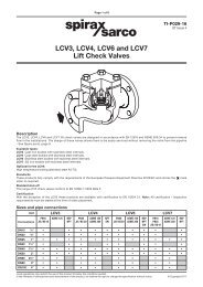
AES14, AES14S and AES14E Austenitic Stainless ... - Spirax Sarco
AES14, AES14S and AES14E Austenitic Stainless ... - Spirax Sarco
AES14, AES14S and AES14E Austenitic Stainless ... - Spirax Sarco

You also want an ePaper? Increase the reach of your titles
YUMPU automatically turns print PDFs into web optimized ePapers that Google loves.
4 Commissioning<br />
After installation or maintenance ensure that the system is fully functioning. Carry out tests on<br />
any alarms or protective devices.<br />
5 Operation<br />
The <strong>AES14</strong> is a ball float type air vent for liquid systems. Any air which is trapped within the<br />
system will migrate to the high points of the system <strong>and</strong> collect, where the <strong>AES14</strong> should be<br />
installed.<br />
The air will enter the body <strong>and</strong> pass through the open valve to atmosphere as the air <strong>and</strong> any<br />
other gases are released, the system liquid enters the body, lifting the ball float, drawing the<br />
valve head to the seat via the action of the lever mechanism, thus closing the valve.<br />
6 Maintenance<br />
Note: Before actioning any maintenance programme observe<br />
the 'Safety information' in Section 1.<br />
Warning<br />
The cover gasket contains a thin stainless steel support ring which may<br />
cause physical injury if not h<strong>and</strong>led <strong>and</strong> disposed of carefully.<br />
6.1 General information<br />
Before undertaking any maintenance on the trap it must be isolated from the supply line <strong>and</strong><br />
any pressure allowed to safely normalise to atmosphere. The air vent should then be allowed to<br />
cool. When reassembling, ensure that all joint faces are clean.<br />
Note: The following Sections need to be read in conjunction with Figure 3, page 7.<br />
6.2 How to fit the main valve assembly - maintenance kit<br />
- Undo the cover bolts (2). Place two screwdrivers between the body <strong>and</strong> cover on either side<br />
<strong>and</strong> lever off the body, keeping bolt holes aligned.<br />
- Remove the pivot pin (14) <strong>and</strong> float assembly (8).<br />
- Remove the two main valve assembly screws (7) <strong>and</strong> pivot frame (12).<br />
- Remove the main valve seat (5) <strong>and</strong> replace with a new seat supplied with new gasket <strong>and</strong><br />
tighten to the recommended torque (see Table 1, page 8).<br />
- Refit the pivot frame (12) by tightening the assembly set screws (7) to the recommended<br />
torque (see Table 1, page 7). Replace float assembly (8) <strong>and</strong> pivot pin (14) .<br />
- Fit a new 'O' ring (15) onto the body ensuring that the 'O' ring contact surfaces are all clean <strong>and</strong><br />
in good condition. Care must be taken to ensure that the 'O' ring is not damaged during<br />
assembly. A suitable lubricant may be used to ease assembly.<br />
- Refit the cover using a new gasket (3) <strong>and</strong> tighten the cover bolts (2). Ensure that the word<br />
'TOP' is uppermost on the body edge. This is relevant to all configurations.<br />
Note: If only the valve cone is being replaced, remove the worn part <strong>and</strong> push the new cone into<br />
the hole in the float lever carefully, insuring the lever does not become distorted.<br />
6<br />
IM-P149-15 ST Issue 1