QLM and QLD Series DN125 to DN200 Three Port ... - Spirax Sarco
QLM and QLD Series DN125 to DN200 Three Port ... - Spirax Sarco
QLM and QLD Series DN125 to DN200 Three Port ... - Spirax Sarco
Create successful ePaper yourself
Turn your PDF publications into a flip-book with our unique Google optimized e-Paper software.
3.563.5275.225<br />
3594050/1<br />
IM-P359-15<br />
CH Issue 1<br />
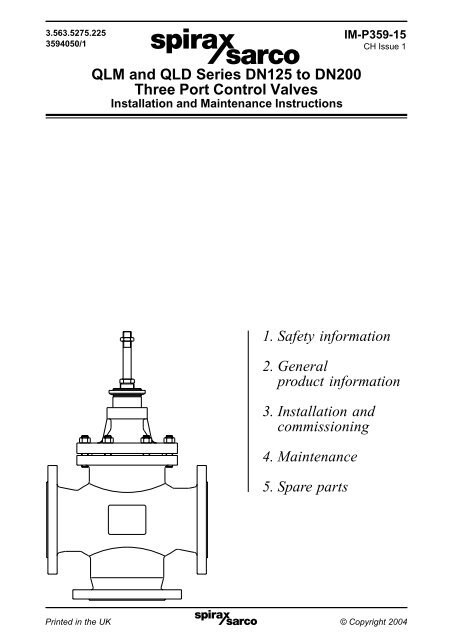
<strong>QLM</strong> <strong>and</strong> <strong>QLD</strong> <strong>Series</strong> <strong>DN125</strong> <strong>to</strong> <strong>DN200</strong><br />
<strong>Three</strong> <strong>Port</strong> Control Valves<br />
Installation <strong>and</strong> Maintenance Instructions<br />
1. Safety information<br />
2. General<br />
product information<br />
3. Installation <strong>and</strong><br />
commissioning<br />
4. Maintenance<br />
5. Spare parts<br />
Printed IM-P359-15 in the CH UK Issue 1 © Copyright 20041
1.1 Intended use<br />
Referring <strong>to</strong> the Installation <strong>and</strong> Maintenance Instructions, name-plate <strong>and</strong> Technical<br />
Information Sheet, check that the product is suitable for the intended use/application.<br />
The products listed below comply with the requirements of the European Pressure<br />
Equipment Directive 97 /23 /EC. The products fall within the following Pressure<br />
Equipment Directive categories:<br />
QL33, QL43, QL63 <strong>and</strong> QL73 <strong>DN125</strong> <strong>to</strong> <strong>DN200</strong> three port control valves:<br />
Group 1 Group 1 Group 2 Group 2<br />
Product<br />
Size<br />
Gas Liquid Gas Liquid<br />
QL33 PN16 - Cast iron <strong>DN125</strong> 2 SEP 1 SEP<br />
QL43 PN16 - Carbon steel<br />
QL63 PN16 - Stainless steel<br />
DN150 3 2 1 SEP<br />
QL73 PN16 - SG iron <strong>DN200</strong> 3 2 1 SEP<br />
QL43 PN25 - Carbon steel <strong>DN125</strong> 2 2 1 SEP<br />
QL63 PN25 - Stainless steel DN150 3 2 2 SEP<br />
QL73 PN25 - SG iron <strong>DN200</strong> 3 2 2 SEP<br />
QL43 PN40 - Carbon steel<br />
QL63 PN40 - Stainless steel<br />
1. Safety information<br />
<strong>DN125</strong> 3 2 2 SEP<br />
DN150 3 2 2 SEP<br />
<strong>DN200</strong> 3 2 2 SEP<br />
I) The products have been specifically designed for use on thermal oil, compressed<br />
air <strong>and</strong> steam or condensate which are in Group 2 of the above mentioned<br />
Pressure Equipment Directive. They can be used on other fluids in accordance<br />
with the above table. If this is contemplated, <strong>Spirax</strong> <strong>Sarco</strong> should be contacted<br />
<strong>to</strong> confirm the suitability of the product for the application being considered.<br />
II)<br />
Check material suitability, pressure <strong>and</strong> temperature <strong>and</strong> their maximum <strong>and</strong><br />
minimum values. If the maximum operating limits of the product are lower than<br />
those of the system in which it is being fitted, or if malfunction of the product<br />
could result in a dangerous overpressure or overtemperature occurrence, ensure<br />
a safety device is included in the system <strong>to</strong> prevent such over-limit situations.<br />
III) Determine the correct installation situation <strong>and</strong> direction of fluid flow.<br />
IV) <strong>Spirax</strong> <strong>Sarco</strong> products are not intended <strong>to</strong> withst<strong>and</strong> external stresses that may<br />
be induced by any system <strong>to</strong> which they are fitted. It is the responsibility of the<br />
installer <strong>to</strong> consider these stresses <strong>and</strong> take adequate precautions <strong>to</strong> minimise them.<br />
V) Remove protection covers from all connections before installation.<br />
1.2 Access<br />
Ensure safe access <strong>and</strong> if necessary a safe working platform (suitably guarded)<br />
before attempting <strong>to</strong> work on the product. Arrange suitable lifting gear if required.<br />
1.3 Lighting<br />
Ensure adequate lighting, particularly where detailed or intricate work is required.<br />
2<br />
IM-P359-15 CH Issue 1
1.4 Hazardous liquids or gases in the pipeline<br />
Consider what is in the pipeline or what may have been in the pipeline at some<br />
previous time. Consider: flammable materials, substances hazardous <strong>to</strong> health,<br />
extremes of temperature.<br />
1.5 Hazardous environment around the product<br />
Consider: explosion risk areas, lack of oxygen (e.g. tanks, pits), dangerous gases,<br />
extremes of temperature, hot surfaces, fire hazard (e.g. during welding), excessive<br />
noise, moving machinery.<br />
1.6 The system<br />
Consider the effect on the complete system of the work proposed. Will any proposed<br />
action (e.g. closing isolation valves, electrical isolation) put any other part of the<br />
system or any personnel at risk? Dangers might include isolation of vents or protective<br />
devices or the rendering ineffective of controls or alarms. Ensure isolation valves are<br />
turned on <strong>and</strong> off in a gradual way <strong>to</strong> avoid system shocks.<br />
1.7 Pressure systems<br />
Ensure that any pressure is isolated <strong>and</strong> safely vented <strong>to</strong> atmospheric pressure.<br />
Consider double isolation (double block <strong>and</strong> bleed) <strong>and</strong> the locking or labelling of<br />
closed valves. Do not assume that the system has depressurised even when the<br />
pressure gauge indicates zero.<br />
1.8 Temperature<br />
Allow time for temperature <strong>to</strong> normalise after isolation <strong>to</strong> avoid danger of burns.<br />
Valves fitted with PTFE components must not be subjected <strong>to</strong> temperatures above<br />
260°C. Above these temperatures <strong>to</strong>xic fumes maybe given off. Avoid inhalation of<br />
fumes or skin contact.<br />
1.9 Tools <strong>and</strong> consumables<br />
Before starting work ensure that you have suitable <strong>to</strong>ols <strong>and</strong> /or consumables<br />
available. Use only genuine <strong>Spirax</strong> <strong>Sarco</strong> replacement parts.<br />
1.10 Protective clothing<br />
Consider whether you <strong>and</strong>/or others in the vicinity require any protective clothing<br />
<strong>to</strong> protect against the hazards of, for example, chemicals, high/low temperature,<br />
radiation, noise, falling objects, <strong>and</strong> dangers <strong>to</strong> eyes <strong>and</strong> face.<br />
1.11 Permits <strong>to</strong> work<br />
All work must be carried out or be supervised by a suitably competent person.<br />
Installation <strong>and</strong> operating personnel should be trained in the correct use of the<br />
product according <strong>to</strong> the Installation <strong>and</strong> Maintenance Instructions.<br />
Where a formal 'permit <strong>to</strong> work' system is in force it must be complied with. Where<br />
there is no such system, it is recommended that a responsible person should know<br />
what work is going on <strong>and</strong>, where necessary, arrange <strong>to</strong> have an assistant whose<br />
primary responsibility is safety.<br />
Post 'warning notices' if necessary.<br />
IM-P359-15 CH Issue 1 3
1.12 H<strong>and</strong>ling<br />
Manual h<strong>and</strong>ling of large <strong>and</strong> /or heavy products may present a risk of injury. Lifting,<br />
pushing, pulling, carrying or supporting a load by bodily force can cause injury<br />
particularly <strong>to</strong> the back. You are advised <strong>to</strong> assess the risks taking in<strong>to</strong> account the<br />
task, the individual, the load <strong>and</strong> the working environment <strong>and</strong> use the appropriate<br />
h<strong>and</strong>ling method depending on the circumstances of the work being done.<br />
1.13 Residual hazards<br />
In some cases the product is provided with pre-compressed springs. Any operation<br />
<strong>to</strong> open the spring housing is <strong>to</strong> be carried out strictly following the correct procedure<br />
given in the Installation <strong>and</strong> Maintenance Instructions. In normal use the external<br />
surface of the product may be very hot. If used at the maximum permitted operating<br />
conditions the surface temperature of some products may reach temperatures of<br />
400°C. Many products are not self-draining. Take due care when dismantling or<br />
removing the product from an installation (refer <strong>to</strong> 'Maintenance instructions').<br />
1.14 Freezing<br />
Provision must be made <strong>to</strong> protect products which are not self-draining against frost<br />
damage in environments where they may be exposed <strong>to</strong> temperatures below freezing<br />
point.<br />
1.15 Disposal<br />
Unless otherwise stated in the Installation <strong>and</strong> Maintenance Instructions, this product<br />
is recyclable <strong>and</strong> no ecological hazard is anticipated with its disposal providing due<br />
care is taken. However, if the valve is fitted with a PTFE component special care must<br />
be taken <strong>to</strong> avoid potential health hazards associated with decomposition/burning<br />
of these parts.<br />
PTFE:<br />
- Can only be disposed of by approved methods, not incineration.<br />
- Keep PTFE waste is a separate container, do not mix it with other rubbish, <strong>and</strong><br />
consign it <strong>to</strong> l<strong>and</strong>fill site.<br />
1.16 Returning products<br />
Cus<strong>to</strong>mers <strong>and</strong> s<strong>to</strong>ckists are reminded that under EC Health, Safety <strong>and</strong> Environment<br />
Law, when returning products <strong>to</strong> <strong>Spirax</strong> <strong>Sarco</strong> they must provide information on any<br />
hazards <strong>and</strong> the precautions <strong>to</strong> be taken due <strong>to</strong> contamination residues or mechanical<br />
damage which may present a health, safety or environmental risk. This information<br />
must be provided in writing including Health <strong>and</strong> Safety data sheets relating <strong>to</strong> any<br />
substances identified as hazardous or potentially hazardous.<br />
4<br />
IM-P359-15 CH Issue 1
2. General product information<br />
2.1 Description<br />
The <strong>QLM</strong> <strong>and</strong> <strong>QLD</strong> are three port control valves which have linear characteristics for mixing or<br />
diverting service. They are available in four body materials: cast iron, SG iron, carbon steel or<br />
stainless steel. All valves can be supplied with the st<strong>and</strong>ard metal-<strong>to</strong>-metal seats, stellite facing for<br />
increased resistance <strong>to</strong> wear or soft seats for tight shut-off. The st<strong>and</strong>ard stem sealing is by spring<br />
adjusted PTFE chevrons but high temperature graphite seals or metal bellows with supplementary<br />
safety packing may also be specified.<br />
The <strong>QLM</strong> <strong>and</strong> <strong>QLD</strong> three port control valves can be used with the following actua<strong>to</strong>rs:<br />
Pneumatic:<br />
PN1000 series, PN2000 series, PN5000 series,<br />
Electric: EL5600 series<br />
PN6000 series, PN7000 series <strong>and</strong> the PN8000 series<br />
2.2 Sizes <strong>and</strong> pipe connections<br />
All valve flanges referred <strong>to</strong> in this document are in accordance with EN 1092.<br />
Type Body material Connection Size range<br />
QL33M Cast iron PN16 <strong>DN125</strong> <strong>to</strong> <strong>DN200</strong><br />
<strong>QLM</strong>: Mixing service<br />
QL43M* Carbon steel PN25/ PN40 <strong>DN125</strong> <strong>to</strong> <strong>DN200</strong><br />
QL63M* Stainless steel PN25/ PN40 <strong>DN125</strong> <strong>to</strong> <strong>DN200</strong><br />
QL73M SG iron PN16/ PN25 <strong>DN125</strong> <strong>to</strong> <strong>DN200</strong><br />
QL33D Cast iron PN16 <strong>DN125</strong> <strong>to</strong> <strong>DN200</strong><br />
<strong>QLD</strong>: Diverting service<br />
QL43D* Carbon steel PN25/ PN40 <strong>DN125</strong> <strong>to</strong> <strong>DN200</strong><br />
QL63D* Stainless steel PN25/ PN40 <strong>DN125</strong> <strong>to</strong> <strong>DN200</strong><br />
QL73D SG iron PN16/ PN25 <strong>DN125</strong> <strong>to</strong> <strong>DN200</strong><br />
* Note: QL43M, QL43D, QL63M <strong>and</strong> QL63D three port control valves are also available with<br />
PN16 flanges by special order.<br />
2.3 Technical data<br />
Plug design<br />
"V" <strong>Port</strong><br />
Plug characteristic<br />
Linear<br />
Leakage class Metal-<strong>to</strong>-metal seal IEC 534-4 Class IV (0.01% of K v )<br />
Rangeability 30:1<br />
Travel <strong>DN125</strong> - <strong>DN200</strong> 50 mm<br />
2.4 Product limitations<br />
Bonnet<br />
Material Body St<strong>and</strong>ard Extended Bellows<br />
PTFE Graphite PTFE Graphite PN16 PN25<br />
Cast iron Pressure (bar) 16 13 16 13 16 13 - - - - 16 13 - -<br />
(PN16) Temperature (°C) -5/+120 200 -5/+120 200 -5/+120 200 - - - - -5/+120 200 - -<br />
SG iron Pressure (bar) 25 15 25 18.7 25 18 25 18 25 15 16 11 25 15<br />
(PN25) Temperature (°C) -10/+120 300 -5/+120 232 -5/+120 250 -10/+120 250 -10/+120 300 -10/+120 300 -10/+120 300<br />
Carbon steel Pressure (bar) 40 21 40 33 40 32 40 32 40 21 16 10 25 16<br />
(PN40) Temperature (°C) -29/+120 400 -5/+120 232 -5/+120 250 -29/+120 250 -29/+120 400 -10/+120 350 -10/+120 350<br />
Stainless steel Pressure (bar) 40 22.1 40 26.8 40 26.2 40 26.2 40 22 16 10 25 16<br />
(PN40) Temperature (°C) -29/+120 400 -5/+120 232 -5/+120 250 -29/+120 250 -29/+129 400 -10/+120 350 -10/+120 350<br />
Notes:<br />
1. Hydrostatic test pressure - 1.5 times the maximum working pressure.<br />
2. Maximum differential pressure - To establish maximum differential pressures see<br />
<strong>Spirax</strong> <strong>Sarco</strong> TIs for the relavent pneumatic or electric actua<strong>to</strong>r.<br />
IM-P359-15 CH Issue 1 5
2.5 Materials<br />
2.5.1 Cast iron, SG iron <strong>and</strong> carbon steel valves<br />
Type No. Part Material Material designation<br />
ASTM/DIN STD<br />
1 Body Cast iron DIN 1691 GG 25<br />
Cast iron 2 St<strong>and</strong>ard bonnet SG iron DIN 1693 GGG 40.3<br />
Extended bonnet Carbon steel DIN 17243 C22.8<br />
1 Body SG iron DIN 1693 GGG 40.3<br />
SG iron 2 St<strong>and</strong>ard bonnet SG iron DIN 1693 GGG 40.3<br />
Carbon steel<br />
Extended bonnet Carbon steel DIN 17243 C22.8<br />
1 Body Carbon steel DIN 17245 GG C25<br />
2<br />
St<strong>and</strong>ard bonnet Carbon steel DIN 16 MnCr 5<br />
Extended bonnet Carbon steel DIN 17243 C22.8<br />
3 Plug(s) Stainless steel BS 970 431 S29<br />
4 Valve seats Stainless steel BS 970 431 S29<br />
5<br />
Valve stem Stainless steel BS 970 431 S29<br />
Bellows Stainless steel AISI 316 L<br />
6 Spacer Stainless steel AISI 304<br />
7 Stuffing box gasket Graphite<br />
8 Lock-nut Stainless steel AISI 304<br />
9 Stuffing box Stainless steel BS 970 431 S29<br />
Cast iron 10 Mounting nut Zinc plated steel NFA 35553 XC 18S<br />
SG iron 11 Packing PTFE/graphite PTFE/graphite<br />
Carbon steel 12 Spring Stainless steel BS 2056 316 S42<br />
13 Bonnet gasket Graphite<br />
14 Stud Carbon steel A193 B7M<br />
15 Nut Carbon steel A194 Gr. 2H<br />
16 Lock-nut Stainless steel AISI 316<br />
17 Guide bush PTFE<br />
18 Stem guide bush Stainless steel Hardened AISI 440B<br />
19 Lock-nut Stainless steel AISI 316<br />
20 Pin Stainless steel AISI 316<br />
21 Gasket Graphite<br />
22 Anti-rotation screw Stainless steel AISI 304<br />
23 Washer Stainless steel AISI 304<br />
6<br />
IM-P359-15 CH Issue 1
8<br />
9<br />
10<br />
11<br />
12<br />
11<br />
14<br />
2<br />
5<br />
23<br />
23<br />
15<br />
13<br />
18<br />
1<br />
4<br />
4<br />
20<br />
3<br />
16<br />
Fig. 1 Mixing valve<br />
8<br />
9<br />
10<br />
11<br />
12<br />
11<br />
14<br />
2<br />
16<br />
1<br />
4<br />
6<br />
4<br />
5<br />
23<br />
23<br />
15<br />
13<br />
18<br />
20<br />
3<br />
3<br />
16<br />
Fig. 2 Diverting valve<br />
IM-P359-15 CH Issue 1 7
2.5.2 Stainless steel valves<br />
Type No. Part Material Material designation<br />
ASTM/DIN STD<br />
1 Body Stainless steel DIN 17445 1.4581<br />
2<br />
St<strong>and</strong>ard bonnet Stainless steel DIN 17445 1.4581<br />
Extended bonnet Stainless steel ASTM A182 F316<br />
3 Valve plug Stainless steel ASTM A351 CF8M<br />
4 Valve seat Stainless steel ASTM A276 316L<br />
5<br />
Valve stem Stainless steel ASTM A276 316L<br />
Bellows Stainless steel AISI 316 L<br />
6 Spacer Stainless steel AISI 316<br />
7 Stuffing box gasket Stainless steel AISI 304<br />
8 Lock-nut Stainless steel AISI 316<br />
9 Stuffing box Stainless steel AISI 316<br />
10 Mounting nut Zinc plated steel NFA 35553 XC 18S<br />
Stainless steel 11 Packing PTFE/graphite PTFE/graphite<br />
12 Spring Stainless steel BS 2056 316 S42<br />
13 Bonnet gasket Graphite<br />
14 Stud Stainless steel A193 B8<br />
15 Nut Stainless steel A194 Gr. 304<br />
16 Lock-nut Stainless steel AISI 316<br />
17 Guide bush PTFE<br />
18 Stem guide bush Stainless steel Hard faced AISI 316<br />
19 Lock-nut Stainless steel AISI 316<br />
20 Pin Stainless steel AISI 316<br />
21 Gasket Graphite<br />
22 Anti-rotation screw Stainless steel AISI 304<br />
23 Washer Stainless steel AISI 304<br />
8<br />
IM-P359-15 CH Issue 1
2.6 Dimensions <strong>and</strong> weights (approximate) in mm <strong>and</strong> kg<br />
Weights<br />
Sizes Dimensions<br />
St<strong>and</strong>ard Extended<br />
A B C C1* bonnet bonnet<br />
<strong>DN125</strong> 400 200 280 445 78 81<br />
DN150 480 225 300 463 115 118<br />
<strong>DN200</strong> 600 275 370 554 143 147<br />
* C1 dimension is relevant <strong>to</strong> valves with<br />
extended or bellows seal bonnet.<br />
C, C1<br />
B<br />
Fig. 3<br />
A<br />
3. Installation <strong>and</strong> commissioning<br />
Note: Before commencing any installation read the 'Safety information' in Section 1.<br />
3.1 General rules<br />
The valve should be installed in such a position as <strong>to</strong> allow full access <strong>to</strong> the valve <strong>and</strong> the<br />
actua<strong>to</strong>r for maintenance purposes. Prior <strong>to</strong> fitting the valve <strong>to</strong> the pipework it should be<br />
flushed clear <strong>to</strong> remove any debris or other particles.<br />
Remove the flange protec<strong>to</strong>rs <strong>and</strong> fit the valve in<strong>to</strong> the pipeline ensuring that the direction<br />
of flow arrows on the body are correct.<br />
Care should be taken <strong>to</strong> prevent any strain being imposed on the valve body due <strong>to</strong> pipe<br />
misalignment. Care should be taken <strong>to</strong> ensure that the valve/actua<strong>to</strong>r spindle is not<br />
painted or coated with any other substance.<br />
3.2 Bypass arrangements<br />
It is recommended that isolating valves be fitted upstream <strong>and</strong> downstream of the control<br />
valve. A bypass can be fitted around the valve with a manual regulating valve allowing the<br />
process <strong>to</strong> be controlled whilst the control valve is isolated for maintenance.<br />
3.3 Commissioning<br />
For commissioning instructions refer <strong>to</strong> the Installation <strong>and</strong> Maintenance Instructions<br />
covering the <strong>Spirax</strong> <strong>Sarco</strong> actua<strong>to</strong>rs.<br />
IM-P359-15 CH Issue 1 9
4. Maintenance<br />
Note: Before commencing any installation read the 'Safety information' in Section 1.<br />
Safety note - H<strong>and</strong>ling precautions<br />
PTFE<br />
Within its working temperature range PTFE is a completely inert material,<br />
but when heated <strong>to</strong> its sintering temperature it gives rise <strong>to</strong> gaseous decomposition<br />
products or fumes which can produce unpleasant effects if inhaled. The inhalation<br />
of these fumes is easily prevented by applying local exhaust ventilation <strong>to</strong><br />
atmosphere as near <strong>to</strong> their source as possible.<br />
Smoking should be prohibited in workshops where PTFE is h<strong>and</strong>led because<br />
<strong>to</strong>bacco contaminated with PTFE will during burning give rise <strong>to</strong> polymer fumes. It<br />
is therefore important <strong>to</strong> avoid contamination of clothing, especially the pockets,<br />
with PTFE <strong>and</strong> <strong>to</strong> maintain a reasonable st<strong>and</strong>ard or personal cleanliness by<br />
washing h<strong>and</strong>s <strong>and</strong> removing any PTFE particles lodged under the fingernails.<br />
LAMINATED GASKETS<br />
The metal foil sheet used <strong>to</strong> reinforce gaskets is very thin <strong>and</strong> sharp. Care should<br />
be taken when h<strong>and</strong>ling <strong>to</strong> avoid the possibility of cuts or lacerations <strong>to</strong> fingers<br />
or h<strong>and</strong>s.<br />
4.1 Periodic maintenance<br />
After 24 hours of operation<br />
After 24 hours of operation check the flange bolts for tightness.<br />
On valves with graphite stem seal packing compress the gl<strong>and</strong> seal packing by tightening<br />
the gl<strong>and</strong> nut by ¼ of a turn. Care should be taken not <strong>to</strong> overtighten as this may cause the<br />
spindle <strong>to</strong> lock-up.<br />
Every 3 months of operation<br />
Every 3 months of normal operation check the stem gl<strong>and</strong> seal for leakage. In the case of<br />
leakage proceed as follows:<br />
- For valves with a PTFE gl<strong>and</strong> seal renew the gl<strong>and</strong> seal by following the procedure in<br />
Section 4.2.1<br />
- For valves with a graphite stem seal packing compress the gl<strong>and</strong> seal packing by<br />
tightening the gl<strong>and</strong> nut by ¼ of a turn. If leakage cannot be eliminated, renew the graphite<br />
gl<strong>and</strong> seal by following the procedure in Section 4.2.2.<br />
Annually<br />
Inspect the valve <strong>to</strong> check for wear or scale deposits. Worn or damaged parts, like the plug<br />
or seat may need <strong>to</strong> be replaced, as well as the gl<strong>and</strong> seal packing.<br />
The graphite packing is normally subject <strong>to</strong> wear. Therefore it is recommended <strong>to</strong> renew<br />
the packing rings annually.<br />
10<br />
IM-P359-15 CH Issue 1
4.2 Valves with packing stem seal<br />
4.2.1 Procedure for renewing the PTFE chevron gl<strong>and</strong> seals <strong>and</strong> graphite ring<br />
gl<strong>and</strong> seals (Refer <strong>to</strong> Figures 1, 2 <strong>and</strong> 4):<br />
a) Isolate the valve on three ports.<br />
b) Remove the actua<strong>to</strong>r from the valve. Refer <strong>to</strong> Installation <strong>and</strong> Maintenance Instructions<br />
covering <strong>Spirax</strong> <strong>Sarco</strong> Actua<strong>to</strong>rs.<br />
c) Remove lock-nut (8).<br />
CAUTION: Care should be taken when removing the stem seal or bonnet since fluid under<br />
pressure may be trapped between the isolating valves.<br />
d) Unscrew <strong>and</strong> remove the gl<strong>and</strong> nut (9). Unscrew the bonnet nuts (15) <strong>and</strong> withdraw the<br />
bonnet (2) taking care not <strong>to</strong> damage the spindle surface.<br />
e) Using a soft metal (brass) hooked <strong>to</strong>ol remove the packing (11), the washers (23) <strong>and</strong> the<br />
spring (12) from the bonnet (2).<br />
f) Examine parts for signs of damage or wear <strong>and</strong> renew as necessary. Note that score marks<br />
or scaly deposits on the valve stem (5) will lead <strong>to</strong> early failure of the seals.<br />
Clean the parts taking care <strong>to</strong> avoid scratching the stem or bore of the packing chamber.<br />
g) Using a new gasket (13) refit the bonnet. Replace <strong>and</strong> finger tighten the bonnet nuts (15) <strong>and</strong><br />
while pushing the valve stem so that the valve plug is on the seat, finally tighten them <strong>to</strong> the<br />
recommended <strong>to</strong>rque as given in Table 1, page 15.<br />
h) Insert washers, spring <strong>and</strong> new PTFE or graphite ring gl<strong>and</strong> seals in<strong>to</strong> the packing<br />
chamber following the sequence shown in Figure 4, care being taken <strong>to</strong> avoid damage <strong>to</strong><br />
the sealing edges.<br />
i) Refit the gl<strong>and</strong> nut (9) <strong>and</strong> tighten untill resistance is felt <strong>and</strong> unscrew by two turns.<br />
j) Ensure that the stem (5) moves freely.<br />
k) Refit valve lock-nut (8).<br />
l) Bring the valve back in<strong>to</strong> service.<br />
m) Check for leakage at the gl<strong>and</strong>.<br />
8<br />
9<br />
5<br />
2<br />
11<br />
23<br />
15<br />
11<br />
12<br />
23<br />
Fig. 4<br />
IM-P359-15 CH Issue 1 11
4.2.2 Procedure for renewing the valve stem (Refer <strong>to</strong> Figures 4, 5 <strong>and</strong> 6):<br />
Mixing valve<br />
Follow the instructions given in<br />
Section 4.2.1 a) <strong>to</strong> f).<br />
5<br />
g) Remove the lock pin (20) <strong>and</strong><br />
unscrew the valve stem (5) from<br />
the spacer (6).<br />
h) Fit the new valve stem (5) in<strong>to</strong><br />
the spacer (6).<br />
Drill a 5 mm diameter hole in the<br />
valve stem in line with that in the<br />
spacer. Refit the lock pin (20).<br />
Complete the reassembly by following<br />
the instructions given in Section 4.2.1<br />
i) <strong>to</strong> m).<br />
20<br />
6<br />
Fig. 5 Mixing valve<br />
Diverting valve<br />
Follow the instructions given in<br />
Section 4.3.3 a) <strong>to</strong> f).<br />
5<br />
g) Undo the lock-nuts (16) <strong>and</strong><br />
remove the valve stem (5).<br />
h) Fit the new valve stem (5) by<br />
passing it through the upper plug<br />
(3a), the spacer (6) <strong>and</strong> the lower<br />
plug (3b) before refitting the locknuts<br />
(16).<br />
Complete the reassembly by following<br />
the instructions given in Section 4.1.3<br />
i) <strong>to</strong> m).<br />
20<br />
3a<br />
6<br />
3b<br />
16<br />
16<br />
Fig. 6 Diverting valve<br />
12<br />
IM-P359-15 CH Issue 1
4.2.3 Procedure for renewing the valve stem, plug <strong>and</strong> seats on mixing<br />
valves (Refer <strong>to</strong> Figures 4 <strong>and</strong> 7):<br />
a) Isolate <strong>and</strong> remove the valve from the pipework.<br />
CAUTION: Care should be taken when removing the valve since fluid under pressure may be<br />
trapped between the isolating valves.<br />
b) Remove the actua<strong>to</strong>r from the valve. Refer <strong>to</strong> the Installation <strong>and</strong> Maintenance Instructions<br />
covering <strong>Spirax</strong> <strong>Sarco</strong> actua<strong>to</strong>rs.<br />
c) Remove the lock-nut (8).<br />
d) Unscrew the nuts (15) securing the bonnet <strong>and</strong> withdraw the bonnet (2).<br />
e) Remove the gl<strong>and</strong> packing as per Section 4.2.1.<br />
f) Ensure that the valve stem (5) is held still by locating a spanner on<strong>to</strong> the machined flat then<br />
unscrew the plug lock-nut (16), from the valve stem (5). (When the flat on the valve stem is<br />
not easily accessible, lock two nuts on<strong>to</strong> the valve stem <strong>and</strong> use a spanner on these <strong>to</strong> prevent<br />
the stem from rotating).<br />
g) Unscrew <strong>and</strong> remove the <strong>to</strong>p valve seat (4). Withdraw the valve plug (3), <strong>and</strong> then unscrew<br />
<strong>and</strong> remove the bot<strong>to</strong>m valve seat (4).<br />
Note: To remove <strong>and</strong> replace the valve seats (4) a special <strong>to</strong>ol is required which can be<br />
obtained from <strong>Spirax</strong> <strong>Sarco</strong> by quoting the valve type <strong>and</strong> size.<br />
h) Lightly smear the threads of the new valve seats with silicon grease. Insert the new bot<strong>to</strong>m<br />
valve seat (4) in<strong>to</strong> the body. Tighten <strong>to</strong> the recommended <strong>to</strong>rque (see Table 1, page 15).<br />
Carefully insert the valve plug (3). Fit the new <strong>to</strong>p valve seat (4) in<strong>to</strong> the body <strong>and</strong> tighten <strong>to</strong><br />
the recommended <strong>to</strong>rque (see Table 1, page 15).<br />
i) Insert the new valve stem (5) in<strong>to</strong> the valve plug (3). Ensure the valve stem (5) is held still<br />
by locating a spanner on <strong>to</strong> the machined flat on the spindle. Replace the valve plug nut<br />
<strong>and</strong> lock-nut (16) <strong>and</strong> tighten <strong>to</strong> the recommended <strong>to</strong>rque (see Table 1, page 15)<br />
j) Using a new gasket (13) refit the bonnet (2), taking care not <strong>to</strong> damage the valve stem (5).<br />
Replace <strong>and</strong> finger tighten the<br />
bonnet nuts (15).<br />
k) Fit the packing gl<strong>and</strong> seal<br />
according <strong>to</strong> the procedure in<br />
8<br />
Section 4.1.1, ensuring the<br />
5<br />
valve stem (5) moves freely<br />
after assembly.<br />
l) Again loosen the bonnet nuts<br />
(15) <strong>and</strong>, while pushing the<br />
valve stem so that the valve<br />
plug is on the bot<strong>to</strong>m seat,<br />
15<br />
2<br />
finally tighten them <strong>to</strong> the<br />
recommended <strong>to</strong>rque (see<br />
13<br />
Table 1, page 15).<br />
m) Refit lock-nut (8). Refit the<br />
actua<strong>to</strong>r <strong>and</strong> connect it <strong>to</strong> the<br />
valve stem.<br />
4<br />
n) Bring the valve back in<strong>to</strong><br />
service.<br />
3<br />
o) Check for leakage around all<br />
4<br />
gasket joints.<br />
16<br />
Fig. 7 Mixing valve<br />
IM-P359-15 CH Issue 1 13
4.2.4 Procedure for renewing the valve stem, plug <strong>and</strong> seats on diverting<br />
valves (Refer <strong>to</strong> Figures 4 <strong>and</strong> 8):<br />
a) Isolate <strong>and</strong> remove the valve from the pipework.<br />
CAUTION: Care should be taken when removing the valve since fluid under pressure may be<br />
trapped between the isolating valves.<br />
b) Remove the actua<strong>to</strong>r from the valve. Refer <strong>to</strong> the Installation <strong>and</strong> Maintenance Instructions<br />
covering <strong>Spirax</strong> <strong>Sarco</strong> Actua<strong>to</strong>rs.<br />
c) Remove the lock-nut (8).<br />
d) Unscrew the nuts (15) securing the bonnet <strong>and</strong> withdraw the bonnet (2).<br />
e) Remove the gl<strong>and</strong> packing as per Section 4.2.1.<br />
f) Ensure that the valve stem (5) is held still by locating a spanner on<strong>to</strong> the machined flat then<br />
unscrew the valve plug lock-nut (16) of the lower valve plug (3). Withdraw the lower valve<br />
plug (3). (When the flat on the valve stem is not easily accessible, lock two nuts on<strong>to</strong> the valve<br />
stem <strong>and</strong> use a spanner on these <strong>to</strong> prevent the stem from rotating).<br />
g) Withdraw the valve stem (5) with upper valve plug (3).<br />
h) Unscrew <strong>and</strong> remove the <strong>to</strong>p <strong>and</strong> bot<strong>to</strong>m valve seats (4).<br />
Note: To remove <strong>and</strong> replace the valve seats (4) a special <strong>to</strong>ol is required which can be<br />
obtained from <strong>Spirax</strong> <strong>Sarco</strong> by quoting the valve type <strong>and</strong> size.<br />
i) Lightly smear the threads of the new valve seats with silicon grease. Insert the new<br />
bot<strong>to</strong>m valve seat (4) in<strong>to</strong> the body. Tighten <strong>to</strong> the recommended <strong>to</strong>rque (see Table 1,<br />
page 15). Insert the new <strong>to</strong>p valve seat (4) in<strong>to</strong> the body. Tighten <strong>to</strong> the recommended <strong>to</strong>rque<br />
(see Table 1, page 15).<br />
j) Unscrew the lock-nut (16) <strong>and</strong> remove the bot<strong>to</strong>m valve plug from the new spindle <strong>and</strong><br />
plug assembly. Insert the new <strong>to</strong>p valve plug (3) in<strong>to</strong> the <strong>to</strong>p valve seat (4). Insert the new<br />
bot<strong>to</strong>m valve plug (3) in<strong>to</strong> the bot<strong>to</strong>m valve seat (4). Ensure the valve stem (5) is held still by<br />
locating a spanner on <strong>to</strong> the machined flat <strong>and</strong> fit the valve plug nut <strong>and</strong> lock-nut (16).<br />
Tighten <strong>to</strong> the recommended<br />
<strong>to</strong>rque (see Table 1, page 15).<br />
k) Using a new gasket (13) refit<br />
8<br />
the bonnet (2), taking care not<br />
<strong>to</strong> damage the valve stem (5).<br />
5<br />
Replace <strong>and</strong> finger tighten the<br />
bonnet nuts (15).<br />
l) Fit the packing gl<strong>and</strong> seal<br />
according <strong>to</strong> procedure in<br />
Section 4.2.1, ensuring the<br />
valve stem (5) moves freely<br />
after assembly.<br />
2<br />
15<br />
m) Again loosen the bonnet nuts<br />
(15) <strong>and</strong>, while pushing the<br />
valve stem so that the valve 16<br />
plug is on the <strong>to</strong>p seat, finally<br />
3<br />
tighten them <strong>to</strong> the correct<br />
4<br />
<strong>to</strong>rque (see Table 1, page 15).<br />
n) Refit lock-nut (8). Refit the<br />
actua<strong>to</strong>r <strong>and</strong> connect it <strong>to</strong> the<br />
4<br />
valve stem.<br />
3<br />
o) Bring the valve back in<strong>to</strong><br />
service.<br />
p) Check for leakage around all<br />
16<br />
gasket joints.<br />
Fig. 8 Diverting valve<br />
14<br />
IM-P359-15 CH Issue 1
4.3 Bellows sealed valves<br />
4.3.1 Procedure for renewing the bellows stem seals (Refer <strong>to</strong> Figure 9):<br />
a) Isolate the valves on all three ports.<br />
CAUTION: Care should be taken in removing<br />
the stem seal if the bellows has failed, since<br />
fluid under pressure may be trapped between<br />
the isolating valves.<br />
b) Remove the actua<strong>to</strong>r from the valve.<br />
CAUTION: take care not <strong>to</strong> rotate the valve<br />
stem when removing the actua<strong>to</strong>r from valve<br />
service, as this will damage the bellows.<br />
Refer <strong>to</strong> the Installation <strong>and</strong> Maintenance<br />
Instructions covering <strong>Spirax</strong> <strong>Sarco</strong> actua<strong>to</strong>rs.<br />
c) Remove the lock-nut (8).<br />
d) Unscrew the gl<strong>and</strong> nut (9), remove the<br />
washer (23) <strong>and</strong> discard the stem seal set<br />
(11).<br />
e) Examine parts for signs of damage or<br />
deterioration <strong>and</strong> renew as necessary. Note:<br />
the stem seal set on this valve is intended<br />
for emergency use in the event of bellows<br />
failure. Score marks or scaly deposits on the<br />
valve stem (5) will impair sealing efficiency.<br />
f) Clean the parts taking care <strong>to</strong> avoid scratching<br />
the stem or bore of the bellows assembly <strong>to</strong>p<br />
end.<br />
g) New graphite stem seals (11) should be<br />
inserted in<strong>to</strong> the bellows assembly <strong>to</strong>p end,<br />
care being taken <strong>to</strong> avoid damage.<br />
h) Refit the washer (23) <strong>and</strong> finger tighten the<br />
gl<strong>and</strong> nut (9) over the valve stem (5).<br />
i) Ensure that the stem (5) moves freely.<br />
j) Refit the valve lock-nut (8).<br />
k) Refit the actua<strong>to</strong>r <strong>and</strong> connect it <strong>to</strong> the valve<br />
stem.<br />
l) Bring the valve back in<strong>to</strong> service.<br />
m) Check for leakage around all gasket joints.<br />
8<br />
9<br />
19<br />
23<br />
11<br />
5<br />
Fig. 9<br />
Table 1 Recommended tightening <strong>to</strong>rques (N m)<br />
Bonnet /Bellows Bellows Plug lock-nut<br />
Valve<br />
Seats (4) housing nuts lock-nut Mixing Diverting<br />
size<br />
(15) (19) (16) (16)<br />
<strong>DN125</strong> 210 - 230 110 - 120 45 - 50 65 - 75 230 - 250<br />
DN150 270 - 290 150 - 160 45 - 50 65 - 75 230 - 250<br />
<strong>DN200</strong> 320 - 340 110 - 120 45 - 50 65 - 75 230 - 250<br />
IM-P359-15 CH Issue 1 15
4.3.2 Procedure for renewing the valve plug, seats <strong>and</strong> bellows assembly<br />
on mixing valves (Refer <strong>to</strong> Figure 10):<br />
CAUTION: Due <strong>to</strong> the delicate nature of the bellows assembly, it is highly recommended that for<br />
renewal of the stem /bellows assembly, valve plug <strong>and</strong>/or seats, the complete valve is returned<br />
<strong>to</strong> <strong>Spirax</strong> <strong>Sarco</strong> service department.<br />
a) Isolate <strong>and</strong> remove the valve from the pipeline. Caution: Care should be taken in removing the<br />
valve since fluid under pressure may be trapped between the isolating valves.<br />
b) Remove the actua<strong>to</strong>r from the valve. Caution: take care not <strong>to</strong> rotate the valve stem (5) when<br />
removing the actua<strong>to</strong>r from the valve, since this will damage the bellows. Refer <strong>to</strong> the Installation<br />
<strong>and</strong> Maintenance Instructions covering <strong>Spirax</strong> <strong>Sarco</strong> actua<strong>to</strong>rs.<br />
c) Remove the lock-nut (8).<br />
d) Ensure that the valve stem (5) is held still by locating a spanner on<strong>to</strong> the machined flat on the<br />
valve stem (5) <strong>and</strong> unscrew the plug lock-nut (16) from the valve stem (5). (When the flat on<br />
the valve stem is not easily accessible, lock two nuts on<strong>to</strong> the valve stem <strong>and</strong> use a spanner<br />
on these <strong>to</strong> prevent the stem from rotating). Unscrew the nuts (15) securing the bonnet (2).<br />
e) Withdraw the bonnet (2) <strong>to</strong>gether with the stem /bellows assembly (5). Remove the gl<strong>and</strong><br />
nut (9) <strong>and</strong> stem seal set (11). Unscrew the stem / bellows assembly lock-nut (19) <strong>and</strong> withdraw<br />
the assembly from the bonnet.<br />
f) Unscrew <strong>and</strong> remove the <strong>to</strong>p valve seat (4). Withdraw the valve plug (3), unscrew <strong>and</strong> remove<br />
the bot<strong>to</strong>m valve seat (4). Note: To remove <strong>and</strong> replace <strong>to</strong>p <strong>and</strong> bot<strong>to</strong>m valve seats (4) a special<br />
<strong>to</strong>ol is required which can be obtained from <strong>Spirax</strong> <strong>Sarco</strong> by quoting the valve type <strong>and</strong> size.<br />
g) Lightly smear the threads of the new seats with silicon grease. Insert the new bot<strong>to</strong>m valve<br />
seat (4) in<strong>to</strong> the body. Tighten <strong>to</strong> the recommended <strong>to</strong>rque (see Table 1, page 15). Carefully<br />
insert the new valve plug (3). Insert the new <strong>to</strong>p seat (4) in<strong>to</strong> the body. Tighten <strong>to</strong> the<br />
recommended <strong>to</strong>rque (see Table 1).<br />
h) Insert the replacement stem /bellows<br />
assembly (5) with a new bellows flange<br />
gasket (21) in<strong>to</strong> the bonnet (2) taking care<br />
not <strong>to</strong> damage the bellows.<br />
Refit the lock-nut (19) <strong>and</strong> tighten <strong>to</strong> the<br />
recommended <strong>to</strong>rque (see Table 1, page 15).<br />
i) Using a new gasket (13) refit the bonnet<br />
<strong>and</strong> stem /bellows assembly on the valve<br />
body ensuring that the valve stem fits in<strong>to</strong><br />
the valve plug bore (3). Replace <strong>and</strong> finger<br />
tighten the bonnet nuts (15). Ensure that<br />
the valve stem (5) is held still by locating a<br />
spanner on <strong>to</strong> the machined flat on<br />
the valve stem (5). Replace the valve plug<br />
nut (16), then tighten <strong>to</strong> the recommended<br />
<strong>to</strong>rque (see Table 1, page 15).<br />
j) Again loosen the bonnet nuts (15) <strong>and</strong>,<br />
while pushing the valve stem so that the<br />
valve plug is on the bot<strong>to</strong>m seat, finally<br />
tighten them <strong>to</strong> the recommended <strong>to</strong>rque<br />
(see Table 1, page 15).<br />
k) Fit a new stem seal assembly (11) as described<br />
in Section 4.2.1, ensuring the valve stem (5)<br />
moves freely after assembly.<br />
l) Refit the actua<strong>to</strong>r <strong>and</strong> connect it <strong>to</strong> the valve<br />
stem. CAUTION: take care not <strong>to</strong> rotate the<br />
valve stem when fitting the actua<strong>to</strong>r <strong>to</strong> the<br />
valve since this will destroy the bellows.<br />
m) Bring the valve back in<strong>to</strong> service.<br />
n) Check for leakage around all gasket joints.<br />
8<br />
9<br />
19<br />
11<br />
21<br />
5<br />
2<br />
15<br />
13<br />
4<br />
3<br />
4<br />
16<br />
Fig. 10 Mixing valve<br />
16<br />
IM-P359-15 CH Issue 1
4.3.3 Procedure for renewing the valve plug, seats <strong>and</strong> bellows assembly<br />
on diverting valves (Refer <strong>to</strong> Figure 11):<br />
CAUTION: Due <strong>to</strong> the delicate nature of the bellows assembly it is highly recommended that for<br />
renewal of the stem /bellows assembly, valve plug <strong>and</strong>/ or seats; the complete valve is returned<br />
<strong>to</strong> the <strong>Spirax</strong> <strong>Sarco</strong> service department.<br />
a) Isolate <strong>and</strong> remove the valve from the pipeline. Caution: Care should be taken in removing<br />
the valve since fluid under pressure may be trapped between the isolating valves.<br />
b) Remove the actua<strong>to</strong>r from the valve. Caution: take care not <strong>to</strong> rotate the valve stem (5) when<br />
removing the actua<strong>to</strong>r from the valve, since this will damage the bellows. Refer <strong>to</strong> the Installation<br />
<strong>and</strong> Maintenance Instructions covering <strong>Spirax</strong> <strong>Sarco</strong> actua<strong>to</strong>rs.<br />
c) Remove the lock-nut (8).<br />
d) Ensure that the valve stem (5) is held still by locating a spanner on<strong>to</strong> the machined flat on the<br />
spacer <strong>and</strong> unscrew the bot<strong>to</strong>m plug lock-nut (16). (When the flat on the valve stem is not<br />
easily accessible, lock two nuts on<strong>to</strong> the valve stem <strong>and</strong> use a spanner on these <strong>to</strong> prevent<br />
the stem from rotating). Unscrew the nuts (15) securing the bonnet (2).<br />
e) Withdraw the bonnet (2) <strong>to</strong>gether with the stem /bellows assembly (5). Remove the gl<strong>and</strong><br />
nut (9) <strong>and</strong> stem seal set (11). Unscrew the stem / bellows assembly lock-nut (19) <strong>and</strong> withdraw<br />
the assembly from the bonnet.<br />
f) Unscrew <strong>and</strong> remove the <strong>to</strong>p valve seat (4), unscrew <strong>and</strong> remove the bot<strong>to</strong>m valve seat (4).<br />
Note: To remove <strong>and</strong> replace the <strong>to</strong>p <strong>and</strong> bot<strong>to</strong>m valve seats (4) a special <strong>to</strong>ol is required<br />
which can be obtained from <strong>Spirax</strong> <strong>Sarco</strong> by quoting the valve type <strong>and</strong> size.<br />
g) Lightly smear the threads of the new seats with silicon grease. Insert the new bot<strong>to</strong>m valve seat<br />
(4) in<strong>to</strong> the body. Tighten <strong>to</strong> the recommended <strong>to</strong>rque (see Table 1, page 15). Insert the new<br />
<strong>to</strong>p valve seat (4) in<strong>to</strong> the body. Tighten <strong>to</strong> the recommended <strong>to</strong>rque (see Table 1, page 15).<br />
h) Remove the bot<strong>to</strong>m valve plug (3) from<br />
the new stem/ bellows assembly (5).<br />
Insert the replacement stem/bellows<br />
assembly (5) with the new bellows flange<br />
gasket (21) in<strong>to</strong> the bonnet (2) taking<br />
care not <strong>to</strong> damage the bellows.<br />
Refit the lock-nut (19) <strong>and</strong> tighten <strong>to</strong><br />
the recommended <strong>to</strong>rque (see Table 1,<br />
page 15).<br />
i) Using a new gasket (13) refit the bonnet<br />
<strong>and</strong> stem/ bellows assembly on the<br />
valve body ensuring that the <strong>to</strong>p<br />
valve plug fits in<strong>to</strong> the valve seat (4).<br />
Replace <strong>and</strong> finger tighten the<br />
bonnet nuts (15). Refit the bot<strong>to</strong>m plug<br />
(3) <strong>and</strong> lock-nuts (16). Note: Ensure<br />
that the valve stem is prevented from<br />
rotating by locating a spanner on <strong>to</strong><br />
the machined flat on the stem <strong>and</strong><br />
tighten <strong>to</strong> the recommended <strong>to</strong>rque<br />
(see Table 1, page 15).<br />
j) Again loosen the bonnet nuts (15) <strong>and</strong>,<br />
while pushing the valve stem so that<br />
the valve plug is on the <strong>to</strong>p seat, finally<br />
tighten them <strong>to</strong> the recommended<br />
<strong>to</strong>rque (see Table 1, page 15).<br />
k) Fit a new stem seal assembly (11)<br />
as described in Section 4.2.1, ensuring<br />
the valve stem (5) moves freely after<br />
assembly.<br />
l) Refit the actua<strong>to</strong>r <strong>and</strong> connect it <strong>to</strong> the<br />
valve stem. CAUTION: take care not <strong>to</strong><br />
rotate the valve stem when fitting the<br />
actua<strong>to</strong>r <strong>to</strong> the valve, since this will<br />
destroy the bellows.<br />
m) Bring the valve back in<strong>to</strong> service.<br />
n) Check for leakage around all gasket joints.<br />
8<br />
9<br />
19<br />
11<br />
21<br />
5<br />
2<br />
15<br />
13<br />
16<br />
3<br />
4<br />
4<br />
3<br />
16<br />
Fig. 11 Diverting valve<br />
IM-P359-15 CH Issue 1 17
5. Spare parts<br />
5.1 Valves with packing gl<strong>and</strong> seal<br />
Available spares<br />
PTFE gl<strong>and</strong> seal kit (spring, bushes <strong>and</strong> packing set) B<br />
Graphite gl<strong>and</strong> seal kit (bush <strong>and</strong> packing set) C<br />
Stem, plug <strong>and</strong> bonnet gasket.<br />
Note: state if the spares ordered are for a mixing or diverting valve D, E<br />
Bonnet gasket (packet of 3) E<br />
Seats (2 items) F<br />
How <strong>to</strong> order spares<br />
Always order spares by using the description given in the column headed 'Available spares' <strong>and</strong><br />
state the size <strong>and</strong> type of valve.<br />
Example: 1 - Gl<strong>and</strong> seal kit for a DN150 QL73D Kvs 300 PN25.<br />
B, C<br />
B, C<br />
E<br />
E<br />
F<br />
D<br />
F<br />
D<br />
F<br />
F<br />
Mixing valve<br />
Fig. 12<br />
Diverting valve<br />
Fig. 13<br />
18<br />
IM-P359-15 CH Issue 1
5.2 Valves with bellows seal<br />
Available spares<br />
Graphite gl<strong>and</strong> seal kit (packing set) AS<br />
Seats (2 items) BS<br />
Bonnet gasket (packet of 3) CS<br />
Bellows gasket (packet of 3) DS<br />
Spindle/bellows <strong>and</strong> plug assembly, gasket, for mixing valves ES, CS, DS<br />
Spindle/bellows <strong>and</strong> plug assembly, gasket, for diverting valves<br />
FS, CS, DS<br />
How <strong>to</strong> order spares<br />
Always order spares by using the description given in the column headed 'Available spares' <strong>and</strong><br />
state the size <strong>and</strong> type of valve.<br />
Example: 1 - Gl<strong>and</strong> seal kit for a DN150 QL73DB1 Kvs 300 PN25.<br />
AS<br />
DS<br />
CS<br />
FS<br />
BS<br />
ES<br />
BS<br />
Mixing valve<br />
Fig. 14<br />
Diverting valve<br />
Fig. 15<br />
IM-P359-15 CH Issue 1 19
20<br />
IM-P359-15 CH Issue 1


