
You also want an ePaper? Increase the reach of your titles
YUMPU automatically turns print PDFs into web optimized ePapers that Google loves.
MINIPAN ® digital panel meters, temperature- and mains controlling,<br />
special purpose instruments for customer requirements www.ziehl.de<br />
ZIEHL industrie-elektronik GmbH+Co, Daimlerstr.13, D-74523 Schwäbisch Hall, Tel.: +49 791 504-0, Fax: -56, e-mail: info@ziehl.de<br />
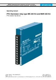
O p e r a t i n g<br />
m a n u a l<br />
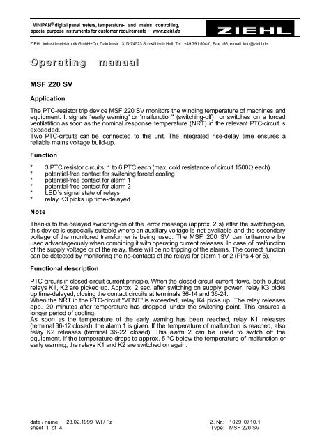
MSF 220 SV<br />
Application<br />
The PTC-resistor trip device MSF 220 SV monitors the winding temperature of machines and<br />
equipment. It signals “early warning" or “malfunction" (switching-off) or switches on a forced<br />
ventilatition as soon as the nominal response temperature (NRT) in the relevant PTC-circuit is<br />
exceeded.<br />
Two PTC-circuits can be connected to this unit. The integrated rise-delay time ensures a<br />
reliable mains voltage build-up.<br />
Function<br />
* 3 PTC resistor circuits, 1 to 6 PTC each (max. cold resistance of circuit 1500Ω each)<br />
* potential-free contact for switching forced cooling<br />
* potential-free contact for alarm 1<br />
* potential-free contact for alarm 2<br />
* LED´s signal state of relays<br />
* relay K3 picks up time-delayed<br />
Note<br />
Thanks to the delayed switching-on of the error message (approx. 2 s) after the switching-on,<br />
this device is especially suitable where an auxiliary voltage is not available and the secondary<br />
voltage of the monitored transformer is being used. The MSF 200 SV can furthermore b e<br />
used advantageously when combining it with operating current releases. In case of malfunction<br />
of the supply voltage or of the relay, there will be no tripping of the alarms. The correct function<br />
can be detected by monitoring the no-contacts of the relays for alarm 1 or 2 (Pins 4 or 5).<br />
Functional description<br />
PTC-circuits in closed-circuit current principle. When the closed-circuit current flows, both output<br />
relays K1, K2 are picked up. Approx. 2 sec. after switching on supply power, relay K3 picks<br />
up time-delayed, closing the contact circuits at terminals 36-14 and 36-24.<br />
When the NRT in the PTC-circuit "VENT" is exceeded, relay K4 picks up. The relay releases<br />
app. 20 minutes after temperature has dropped under the switching point. This ensures a<br />
longer period of cooling.<br />
As soon as the temperature of the early warning has been reached, relay K1 releases<br />
(terminal 36-12 closed), the alarm 1 is given. If the temperature of malfunction is reached, also<br />
relay K2 releases (terminal 36-22 closed). This alarm 2 can be used to switch off the<br />
equipment. If the temperature drops to approx. 5 °C below the temperature of malfunction or<br />
early warning, the relays K1 and K2 are switched on again.<br />
date / name 23.02.1999 Wl / Fz Z. Nr.: 1029 0710.1<br />
sheet 1 of 4 Type: MSF 220 SV
Technical Data<br />
Type-Plate<br />
Order number<br />
Supply voltage Us / frequency<br />
……………………<br />
see type plate<br />
on the device<br />
……………………<br />
Tolerance vottage Us AC 0.9...1.1 Us DC 0.85...1.35 Us<br />
Tolerance frequency Us<br />
48...62Hz<br />
PTC-resistor connection<br />
Cut-out point<br />
Reclosing point<br />
Collective resistance of cold sensors<br />
Terminal voltage (sensors)<br />
3 x 1...6 PTC in series<br />
2,8...3,6 kΩ, typ. 3,2 kΩ<br />
1,8...2,4 kΩ, typ. 2,1 kΩ<br />
≤ 1.5 kΩ<br />
≤ 2.5 V at ≤ 250 Ω<br />
≤ 7.5 V at ≥ 4 kΩ<br />
Relay output<br />
contacts AgCdO<br />
Switching voltage AC max. 400 V DC 110-250 V 0.25 A<br />
Switching current AC max. 8 A DC 60 V 0.5A<br />
Switching power AC max. 1100 VA DC 30 V 1.5 A<br />
Rated continious current I th AC 6 A DC 24 V 5 A<br />
Rated operational current Ie 2A AC15 400 V 2A DC13 24 V<br />
4A AC15 250V<br />
Prefuse for device and contacts AC: T 4 A DC: F 2 A<br />
Mechanical contact life<br />
5 x 10 7 operations<br />
Electrical contact life<br />
2 x 10 5 operations (at max. switching capacity)<br />
Factor of reduction at cos = 0.4<br />
0.6 x max. switching capacity<br />
Switching-on delay<br />
app. 2 sec.<br />
Testing conditions VDE 0660 / VDE 0160<br />
Rated insulation voltage<br />
AC 250 V<br />
Isolation<br />
VDE 110 / Gr. C<br />
Transformer VDE 0550<br />
Test voltage between supply voltage,<br />
relay outputs and sensor side<br />
2.5 kV<br />
On period 100 %<br />
max. ambient temperature -20 ... +55 °C<br />
Climatic category F (according to DIN 40 040)<br />
Housing:<br />
design S-12, plug-in housing<br />
Dimensions (H x W x D)<br />
82 x 42 x 121 mm<br />
Line connection<br />
12-pole, max. 2 x 1.5 mm 2 each<br />
Protection Housing IP 40<br />
Protection contacts IP 20<br />
Panel inclination<br />
any<br />
Mounting<br />
snapable on 35 mm standard rail according to DIN<br />
or assembly with scrwes M 4<br />
Weight<br />
app. 250 g<br />
date / name 23.02.1999 Wl / Fz Z. Nr.: 1029 0710.1<br />
sheet 2 of 4 Type: MSF 220 SV
Installation - Putting into operation<br />
The plug base can be mounted either with<br />
* 35 mm mounting rail according to DIN 50 002 or<br />
* M4 screws<br />
Wiring directly to plug base<br />
* Connect wires as per wiring scheme<br />
* Plug in electronics and fix with knurled screw<br />
Attention!<br />
Do not plug in device alive nor detach it from socket.<br />
When installing the device into the switch-gear cabinet, please observe the max.<br />
admissible temperature. Care for both sufficient clearance to other devices or<br />
sources of heat or enough forced draught. Generally recommended mininum<br />
clearance: 2 cm.<br />
Before switching on make sure that the operational voltage Us of the lateral type<br />
plate and the mains voltage are the same.<br />
* Apply mains voltage to terminals 11 and 12.<br />
* When device is ready for operation, relays “ALARM1” and “ALARM2” switch on<br />
immediately, the LED’s are off. After approx. 2 s. relay “ON” picks up, terminals 3 -<br />
4, 3 - 5 are connected.<br />
* Relay "VENT" picks up, as soon as the input at terminal 7, 10 becomes high-resistive.<br />
* Relay "VENT" releases 20 min. after the input at terminal 7, 10 becomes low-resistive.<br />
* Relay “ALARM1” releases as soon as the input at terminal 8, 10 becomes highresistive.<br />
* Relay “ALARM2” releases as soon as the input at terminal 9, 10 becomes highresistive.<br />
* Relay “ALARM1”, “ALARM2” pick up as soon as the inputs at terminals 8, 10 ; 9,<br />
10 become low-resistive.<br />
* Relay “ON” releases first, as soon as the supply voltage is switched off.<br />
Trouble-shooting and remedies<br />
* Relays are not switched on.<br />
Check whether supply voltage Us at terminal 11, 12 is available and corresponds to<br />
the voltage indicated on the lateral type plate of the device.<br />
* LED´s light up continuously.<br />
Check whether PTC’s at terminals 7-10, 8-10 and 9-10 are connected correctly. Both<br />
PTC’s must be connected and low-resistive.<br />
Attention! Check PTC’s only with measuring voltages of < 2.5 V.<br />
* In case of any other malfunctions, replace device and send it in together with a<br />
description of the occurred malfunction.<br />
date / name 23.02.1999 Wl / Fz Z. Nr.: 1029 0710.1<br />
sheet 3 of 4 Type: MSF 220 SV
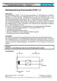
Wiring Scheme<br />
48<br />
VENT.<br />
47<br />
36<br />
ON<br />
35<br />
21<br />
ALARM<br />
2<br />
22<br />
24<br />
ALARM<br />
11 =<br />
1<br />
14<br />
12<br />
1<br />
2<br />
3<br />
4 5 6 7 8 9 10 11 12<br />
A2 A1<br />
~ U S ~<br />
- +<br />
ALARM 2<br />
ALARM 1<br />
VENT.<br />
Design S 12<br />
5<br />
<br />
<br />
<br />
36<br />
82<br />
23,5<br />
80<br />
61<br />
38<br />
17 41<br />
17,5<br />
1<br />
11,5<br />
1<br />
16<br />
2<br />
7,5<br />
10<br />
5<br />
2<br />
5<br />
1 2 3 4 5 7 6 8 9 10 11 12<br />
6 Jacks for coding-pins<br />
82<br />
104,5<br />
116<br />
34<br />
1<br />
3<br />
41,5<br />
Base<br />
<br />
<br />
41,5<br />
1 Cable bushing<br />
2 Mounting bore-hole<br />
3 Unlatching<br />
(only with rail-mounting)<br />
14<br />
27,5<br />
date / name 23.02.1999 Wl / Fz Z. Nr.: 1029 0710.1<br />
sheet 4 of 4 Type: MSF 220 SV