GERWAH Backlash-free Safety Couplings
GERWAH Backlash-free Safety Couplings
GERWAH Backlash-free Safety Couplings

Create successful ePaper yourself
Turn your PDF publications into a flip-book with our unique Google optimized e-Paper software.
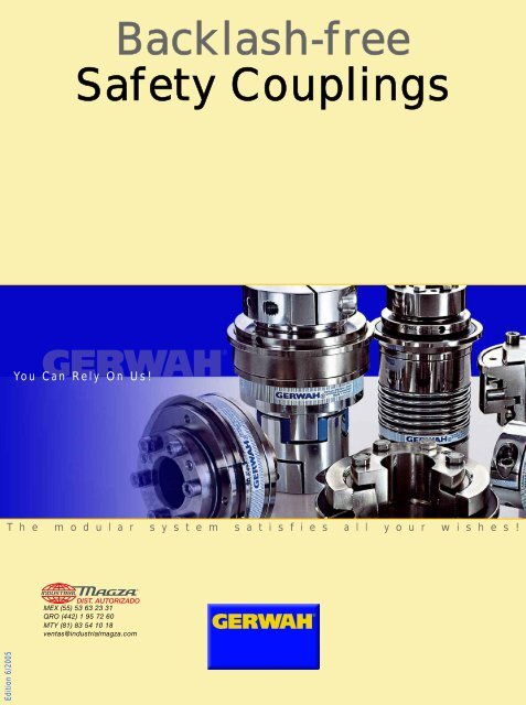
<strong>Backlash</strong>-<strong>free</strong><br />
<strong>Safety</strong> <strong>Couplings</strong><br />
You Can Rely On Us!<br />
T h e m o d u l a r s y s t e m s a t i s f i e s a l l y o u r w i s h e s !<br />
DIST. AUTORIZADO<br />
MEX (55) 53 63 23 31<br />
QRO (442) 1 95 72 60<br />
MTY (81) 83 54 10 18<br />
ventas@industrialmagza.com<br />
®<br />
Edition 6/2005
G E R W A H T h e C o m p a n y<br />
<strong>GERWAH</strong> GmbH was founded in 1980.<br />
The idea of new, innovative products<br />
has made <strong>GERWAH</strong> a recognized partner<br />
in the machine tool industry.<br />
We are a dynamic, spirited and fast<br />
growing company with clear goals and<br />
open mind that is reflected in the<br />
architecture of our new headquarters.<br />
Our Goals<br />
• To add value for our customers by<br />
providing innovative product solutions<br />
• To develop solutions in cooperation<br />
with our customers<br />
• Satisfied customers<br />
Our Advantages<br />
• Know-how, innovative designs and<br />
cutting edge manufacturing plants<br />
• Customer oriented employees<br />
• Technical assistance and service,<br />
both locally and internationally<br />
• Qualified sales force<br />
• Economic stability<br />
• Worldwide presence with<br />
subsidiaries and dealers<br />
Our new headquarters in Grosswallstadt, Germany<br />
<strong>GERWAH</strong> - You Can Rely On Us!<br />
Frankfurt<br />
Hamburg<br />
Grosswallstadt<br />
Munich<br />
Berlin<br />
Prague<br />
Chotesov<br />
Pilsen<br />
DIST. AUTORIZADO<br />
MEX (55) 53 63 23 31<br />
QRO (442) 1 95 72 60<br />
MTY (81) 83 54 10 18<br />
ventas@industrialmagza.com<br />
®<br />
We are certified according to DIN EN ISO 9001 (Cert.-No. 0063-D)<br />
2 info@gerwah.com • www.gerwah.com • Phone 0049-6022-22040 You Can Rely On Us! Fax 0049-6022-220411 • D-63868 Grosswallstadt
Guarantee for your success!<br />
Machine and system protection ‣ High-speed disengagement within 2-4 msec. ‣‣Minimal residial friction<br />
Process control ‣ Accurate adjustment of disengaging torque ‣‣ Signalling of overloads<br />
Process accuracy ‣ <strong>Backlash</strong>-<strong>free</strong> torque transmission ‣‣ Excellent disengagement repeatability after long downtimes<br />
‣‣Easy handling<br />
High dynamics<br />
‣ Low mass moment of inertia<br />
Specific customer solutions ‣High flexibility through modular design<br />
Series<br />
DMK/L<br />
DMK/M<br />
DMK/S<br />
Series DMK/B<br />
Series DMK/E<br />
Technical data: pages 6-7<br />
Technical data: pages 8-9 Technical data: pages 10-11<br />
The detent mechanism: rollers as interlocking elements<br />
Roller<br />
detent<br />
system<br />
Single position reengagement<br />
e.g.<br />
after<br />
360°<br />
Multy position re-engagement<br />
T<br />
Conventional<br />
progressive<br />
characteristic<br />
System <strong>GERWAH</strong> ®<br />
degressive<br />
characteristic<br />
T max.<br />
Switching work<br />
As = f (x1) x S<br />
S<br />
S = Spring travel<br />
S<br />
The details in this catalogue describe<br />
the products and do not represent<br />
guaranteed qualities. The user ®<br />
is responsible DIST. for checking AUTORIZADO and de-<br />
MEX (55) 53 63 23 31<br />
QRO (442) 1 95 72 60<br />
MTY (81) 83 54 10 18<br />
ventas@industrialmagza.com<br />
fining the technical characteristics<br />
of his particular application. We reserve<br />
the right to make changes at<br />
any time without notice. We cannot<br />
be held responsible for any omissions<br />
or printing errors. Deliveries<br />
are based on individual detailed<br />
contractual agreements. <strong>Backlash</strong><strong>free</strong><br />
safety couplings are dangerous<br />
parts and must therefore be protected<br />
by the user against unintentional<br />
handling during operation.<br />
info@gerwah.com • www.gerwah.com • Phone 0049-6022-22040 You Can Rely On Us! Fax 0049-6022-220411 • D-63868 Grosswallstadt<br />
3
Create your own safety coupling!<br />
Our new system allows the user to build<br />
the requested coupling combining basic<br />
coupling elements.<br />
The coupling is composed of three parts:<br />
the coupling body and the two hubs. The<br />
following pages illustrate technical details<br />
of each element. The result is a customer<br />
specific coupling tuned to the requirements<br />
of your application.<br />
Any questions?<br />
Don’t hesitate<br />
to contact us!<br />
Example:<br />
required shaft-hubconnection<br />
required coupling body<br />
required shaft-hubconnection<br />
required coupling<br />
Multiple combinations available!<br />
DIST. AUTORIZADO<br />
MEX (55) 53 63 23 31<br />
QRO (442) 1 95 72 60<br />
MTY (81) 83 54 10 18<br />
ventas@industrialmagza.com<br />
®<br />
4 info@gerwah.com • www.gerwah.com • Phone 0049-6022-22040 You Can Rely On Us! Fax 0049-6022-220411 • D-63868 Grosswallstadt
<strong>Safety</strong> <strong>Couplings</strong> The System<br />
Hub 1<br />
Coupling Body<br />
Hub 2<br />
Type L<br />
Type<br />
DMK<br />
Type M<br />
Type S<br />
Type DMK/B<br />
Data<br />
pages<br />
6-7<br />
Type Ki<br />
Type Kn<br />
Type BKi<br />
Type<br />
BKn/<br />
EKn<br />
Type<br />
DMK/E<br />
Data<br />
pages<br />
8-9<br />
Type Ka<br />
Type<br />
EKa<br />
Data<br />
pages<br />
10-11<br />
Generally: Keyways<br />
acc. DIN 6885-1 on request!<br />
Combining desired!<br />
DIST. AUTORIZADO<br />
MEX (55) 53 63 23 31<br />
QRO (442) 1 95 72 60<br />
MTY (81) 83 54 10 18<br />
ventas@industrialmagza.com<br />
®<br />
info@gerwah.com • www.gerwah.com • Phone 0049-6022-22040 You Can Rely On Us! Fax 0049-6022-220411 • D-63868 Grosswallstadt<br />
5
<strong>Backlash</strong>-<strong>free</strong> <strong>Safety</strong> <strong>Couplings</strong><br />
Series DMK:<br />
<strong>Safety</strong><br />
Coupling<br />
with flange<br />
Type L<br />
standard<br />
Ø B1<br />
Ø C1 ±0,1<br />
Ø F1 g6<br />
Ø D1 H7<br />
G1<br />
N1<br />
L1 ±1<br />
K1<br />
O1<br />
ØA1<br />
flange<br />
side<br />
Series DMK<br />
hub<br />
side<br />
M1<br />
J1 ±1<br />
Ø D4 H7<br />
Type Ki<br />
inner<br />
cone<br />
E1<br />
hub<br />
H1<br />
DIN EN ISO 4762<br />
Type M<br />
Ø B2<br />
Ø C2 ±0,1<br />
Ø F2 g6<br />
Ø D2 H7<br />
N2<br />
L2 ±1<br />
K2<br />
O2<br />
ØA2<br />
S<br />
pure keyway connection<br />
disengaging<br />
travel<br />
M2<br />
J2 ±1<br />
Ø D5 H7<br />
Type Ka<br />
outer<br />
cone<br />
E2<br />
hub<br />
G2<br />
H2<br />
DIN EN ISO 4762<br />
Type S<br />
Ø B3<br />
Ø C3 ±0,1<br />
Ø F3 g6<br />
Ø D3 H7<br />
N3<br />
L3<br />
K3<br />
O3<br />
ØA3<br />
DIN 6885<br />
M3<br />
J3 ±1<br />
Ø D6 H7<br />
Type Kn<br />
clamping<br />
E3<br />
hub<br />
G3<br />
Lges = L (1/2/3) + J (1/2/3)<br />
H3<br />
DIN EN ISO 4762<br />
DIST. AUTORIZADO L<br />
MEX (55) 53 63 23 31<br />
QRO (442) 1 95 72 60<br />
MTY (81) 83 54 10 18<br />
ventas@industrialmagza.com<br />
®<br />
Ki<br />
Ordering<br />
data<br />
example<br />
DMK/L - 150 - Ki/32 H7 - 80Nm/b - C<br />
flange<br />
size<br />
inner conical hub / bore size (mm)<br />
disengaging torque / torque adjustment range<br />
C = single position re-engagement (360°) standard;<br />
(D = multi position re-engagement)<br />
6 info@gerwah.com • www.gerwah.com • Phone 0049-6022-22040 You Can Rely On Us! Fax 0049-6022-220411 • D-63868 Grosswallstadt
Technical Data Series DMK/L, DMK/M, DMK/S<br />
Size<br />
Disengaging torque (Nm)<br />
Torque adjustment range<br />
Moment of inertia<br />
(10 3 Kgm 3 )<br />
Weight (appr. kg)<br />
Tightening torque of<br />
retaining screws<br />
(Nm)<br />
Max. rotational speed (rpm)<br />
Disengaging travel (mm)<br />
TKN version a<br />
TKN version b<br />
J hub side<br />
J flange side<br />
m<br />
MA<br />
MA<br />
MA<br />
nmax<br />
S<br />
H1<br />
H2<br />
H3<br />
30<br />
5-20<br />
15-35<br />
0,2<br />
0,1<br />
0,45<br />
5<br />
5<br />
15<br />
9240<br />
1,2<br />
60<br />
12-35<br />
20-70<br />
0,4<br />
0,2<br />
0,8<br />
8,5<br />
8,5<br />
40<br />
8185<br />
1,2<br />
150<br />
25-75<br />
65-150<br />
1,1<br />
0,6<br />
1,4<br />
14<br />
14<br />
60/55<br />
6230<br />
2<br />
200<br />
50-120<br />
80-200<br />
1,8<br />
0,9<br />
1,7<br />
14<br />
14<br />
100/80<br />
5620<br />
2<br />
300<br />
30-140<br />
100-300<br />
2,6<br />
1,1<br />
2,5<br />
18<br />
18<br />
110/90<br />
5610<br />
2<br />
500<br />
140-350<br />
250-500<br />
6,94<br />
1,3<br />
3,8<br />
26<br />
26<br />
145<br />
4585<br />
2<br />
800<br />
260-600<br />
500-1000<br />
22,7<br />
5,1<br />
11<br />
45<br />
45<br />
3470<br />
2<br />
1200<br />
400-900<br />
800-1400<br />
22,7<br />
5,1<br />
11<br />
80<br />
80<br />
3470<br />
2<br />
Flange L<br />
dimensions (mm)<br />
Flange M<br />
dimensions (mm)<br />
Flange S<br />
dimensions (mm)<br />
Hub Ki<br />
inner cone<br />
dimensions (mm)<br />
Hub Ka<br />
outer cone<br />
dimensions (mm)<br />
Hub Kn<br />
clamping hub<br />
dimensions (mm)<br />
Size<br />
Ø A1<br />
Ø B1<br />
Ø C1<br />
Ø D1 min.-max<br />
Ø F1<br />
G1 6 x thread/depth (mm)<br />
K1<br />
L1<br />
L ges. = L1 + (J1) or (J2) or (J3)<br />
N1<br />
O1<br />
Ø A2<br />
Ø B2<br />
Ø C2<br />
Ø D2 min.-max<br />
Ø F2<br />
G2<br />
K2<br />
L2<br />
L ges.<br />
6 x thread/depth (mm)<br />
= L2 + (J1) or (J2) or (J3)<br />
N2<br />
O2<br />
Ø A3<br />
Ø B3<br />
Ø C3<br />
Ø D3 min.-max<br />
Ø F3<br />
G3<br />
K3<br />
L3<br />
L ges.<br />
6 x thread/depth (mm)<br />
= L3 + (J1) or (J2) or (J3)<br />
N3<br />
O3<br />
Ø D4<br />
H1 6 x DIN EN ISO 4762<br />
J1<br />
M1<br />
E1<br />
Ø D5<br />
H2 6 x DIN EN ISO 4762<br />
J2<br />
M2<br />
E2<br />
Ø D6<br />
H3 1 x DIN EN ISO 4762<br />
J3<br />
M3<br />
E3<br />
30<br />
65<br />
62<br />
46<br />
12-20<br />
37<br />
M5/6<br />
29<br />
36<br />
7<br />
23<br />
65<br />
62<br />
53<br />
9-20<br />
47<br />
M4/7<br />
29<br />
36<br />
7<br />
23<br />
65<br />
62<br />
54<br />
12-20<br />
47<br />
M5/6<br />
30<br />
41<br />
11<br />
23<br />
12-20<br />
M4<br />
12<br />
20<br />
41<br />
12-20<br />
M4<br />
22<br />
30<br />
45<br />
12-20<br />
M6<br />
19<br />
30<br />
47<br />
60<br />
75<br />
72<br />
55<br />
15-25<br />
42<br />
M6/6<br />
30<br />
37<br />
7<br />
24<br />
75<br />
77<br />
69<br />
12-25<br />
62<br />
M5/8<br />
32<br />
37<br />
5<br />
24<br />
75<br />
72<br />
63<br />
15-25<br />
55<br />
M5/8<br />
32<br />
43<br />
11<br />
26<br />
15-25<br />
M6<br />
16<br />
25<br />
54<br />
15-25<br />
M6<br />
28<br />
38<br />
55<br />
15-25<br />
M8<br />
24<br />
40<br />
66<br />
150<br />
95<br />
92<br />
78<br />
20-35<br />
68<br />
M6/9<br />
33<br />
46<br />
13<br />
27<br />
95<br />
92<br />
80<br />
15-35<br />
68<br />
M6/8<br />
36<br />
46<br />
10<br />
27<br />
95<br />
92<br />
78<br />
20-35<br />
68<br />
M6/9<br />
33<br />
45<br />
12<br />
27<br />
20-35<br />
M6<br />
17<br />
30<br />
62<br />
20-35<br />
M6<br />
30<br />
45<br />
51<br />
20-35<br />
M10<br />
26<br />
45<br />
68/76<br />
200<br />
105<br />
102<br />
86<br />
20-40<br />
75<br />
M6/10<br />
35<br />
49<br />
14<br />
30<br />
105<br />
102<br />
90<br />
20-40<br />
80<br />
M6/10<br />
39<br />
49<br />
14<br />
34<br />
105<br />
102<br />
85<br />
20-40<br />
75<br />
M6/10<br />
37<br />
50<br />
12<br />
32<br />
25-40<br />
M6<br />
17<br />
30<br />
68<br />
25-40<br />
M6<br />
26<br />
40<br />
79<br />
25-40<br />
M12<br />
30<br />
50<br />
80/90<br />
300<br />
115<br />
110<br />
90<br />
30-46<br />
80<br />
M8/12<br />
40<br />
54<br />
14<br />
31<br />
115<br />
110<br />
98<br />
30-46<br />
82<br />
M8/10<br />
40<br />
55<br />
15<br />
32<br />
30-45<br />
M6<br />
21<br />
35<br />
76<br />
30-45<br />
M6<br />
35<br />
50<br />
79<br />
30-45<br />
M12<br />
30<br />
50<br />
91/96<br />
500<br />
129<br />
125<br />
110<br />
35-50<br />
95<br />
M8/12<br />
42<br />
52<br />
10<br />
34<br />
129<br />
125<br />
112<br />
35-50<br />
100<br />
M8/12<br />
42<br />
52<br />
10<br />
34<br />
129<br />
125<br />
110<br />
35-50<br />
90<br />
M8/12<br />
46<br />
67<br />
21<br />
38<br />
35-50<br />
M8<br />
21<br />
38<br />
85<br />
35-50<br />
M8<br />
36<br />
53<br />
90<br />
35-50<br />
M12<br />
34<br />
59<br />
110<br />
800<br />
169<br />
165<br />
125<br />
40-60<br />
110<br />
M12/15<br />
62<br />
77<br />
15<br />
48<br />
169<br />
165<br />
120<br />
40-60<br />
100<br />
M10/15<br />
61<br />
82<br />
21<br />
48<br />
40-60<br />
M12<br />
32<br />
60<br />
120<br />
40-70<br />
M12<br />
55<br />
80<br />
139<br />
1200<br />
169<br />
165<br />
125<br />
40-60<br />
110<br />
M12/15<br />
62<br />
77<br />
15<br />
48<br />
40-60<br />
M12<br />
32<br />
60<br />
120<br />
40-70<br />
M12<br />
55<br />
80<br />
139<br />
<strong>Couplings</strong> for torque ranges different from above also available!<br />
DIST. AUTORIZADO<br />
MEX (55) 53 63 23 31<br />
QRO (442) 1 95 72 60<br />
MTY (81) 83 54 10 18<br />
ventas@industrialmagza.com<br />
®<br />
info@gerwah.com • www.gerwah.com • Phone 0049-6022-22040 You Can Rely On Us! Fax 0049-6022-220411 • D-63868 Grosswallstadt<br />
7
<strong>Backlash</strong>-<strong>free</strong> <strong>Safety</strong> <strong>Couplings</strong><br />
Series DMK/B:<br />
<strong>Safety</strong> Coupling<br />
with metal bellow<br />
as torsion-proof<br />
misalignment compensating<br />
element<br />
Type BKn<br />
L1<br />
H1(DIN EN ISO 4762)<br />
Series DMK/B<br />
M3<br />
J1 ±1<br />
Ø D4 H7<br />
Type Ki<br />
inner<br />
cone<br />
hub<br />
Ø B1<br />
Ø C1<br />
Ø D1 H7<br />
Type BKi<br />
Ø B2<br />
Ø C2<br />
Ø D2 H7<br />
L2<br />
F2<br />
M1<br />
M2<br />
H2 (DIN<br />
EN ISO<br />
4017)<br />
switching ring<br />
L1<br />
disengaging travel S<br />
L2<br />
N<br />
ØA<br />
M4<br />
M5<br />
J2 ±1<br />
J3 ±1<br />
H3<br />
(DIN EN ISO 4017)<br />
Ø D5 H7<br />
Ø D6 H7<br />
Type Ka<br />
outer<br />
cone<br />
hub<br />
H4<br />
(DIN EN ISO 4017)<br />
Type Kn<br />
clamping<br />
hub<br />
Lges = L (1/2) + J (1/2/3)<br />
H5<br />
(DIN EN ISO 4762)<br />
DIST. BKn AUTORIZADO<br />
MEX (55) 53 63 23 31<br />
QRO (442) 1 95 72 60<br />
MTY (81) 83 54 10 18<br />
ventas@industrialmagza.com<br />
®<br />
Ki<br />
Ordering<br />
data<br />
example<br />
DMK/B - 60/4 - BKn/25 H7 - Ki/20 H7 - 50Nm/b - C<br />
type<br />
size / bellow 1)<br />
hub on bellow side / Ø<br />
hub on safety element side / Ø<br />
disengaging torque / torque adjustment range<br />
C = single position re-engagement (360°) standard; (D = multi position re-engagement)<br />
1) two metal bellow sizes available: 4 = short bellow, 6 = long bellow<br />
8 info@gerwah.com • www.gerwah.com • Phone 0049-6022-22040 You Can Rely On Us! Fax 0049-6022-220411 • D-63868 Grosswallstadt
Technical Data Series DMK/B<br />
Size<br />
Disengaging torque (Nm) TKN version a<br />
torque adjustment range<br />
TKN version b<br />
Moment of inertia BKn<br />
(10 -3 Kgm 2 )J hub side<br />
J metal bellow side<br />
Moment of inertia BKi<br />
(10 -3 Kgm 2 ) J hub side<br />
J metal bellow side<br />
Weight BKn<br />
(appr. kg) m<br />
Weight BKi<br />
(appr. kg) m<br />
Tightening torque of retaining screw H1(Nm) Ma<br />
Tightening torque of retaining screw H2(Nm) Ma<br />
Tightening torque of retaining screw H3(Nm) Ma<br />
Tightening torque of retaining screw H4(Nm) Ma<br />
Tightening torque of clamp screw H5 (Nm) Ma<br />
Dynamic torsional stiffness (10 3 Nm/rad) CTdyn 4/6 1)<br />
Radial spring stiffness (N/mm) Cr 4/6 1)<br />
Axial spring stiffness (N/mm) Ca 4/6 1)<br />
Max. rotation speed (rpm) nmax<br />
Disengaging travel (mm) S<br />
Max. allowable misalignment: see page 15<br />
BKn clamping hub<br />
dimensions (mm)<br />
BKi inner cone<br />
hub<br />
dimensions (mm)<br />
Size<br />
Ø A<br />
Ø B1<br />
Ø C1<br />
Ø D1 H7 min.<br />
max.<br />
H1 DIN EN ISO 4762<br />
L1 2)<br />
L ges. = L1 + (J1) or (J2) or (J3)<br />
N<br />
M1<br />
Ø A<br />
Ø B2<br />
Ø C2<br />
30<br />
5-20<br />
15-35<br />
0,16<br />
0,16<br />
0,21<br />
0,11<br />
0,7<br />
0,7<br />
15/12<br />
5<br />
5<br />
5<br />
15<br />
36/26<br />
718/222<br />
48/27<br />
9240<br />
1,2<br />
30<br />
65<br />
56<br />
47/65<br />
10/20<br />
20/25<br />
M6<br />
70/78<br />
6<br />
24<br />
65<br />
56<br />
52<br />
12-20<br />
8<br />
M4<br />
64/72<br />
60<br />
12-35<br />
20-70<br />
0,4<br />
0,4<br />
0,53<br />
0,27<br />
1,4<br />
1,5<br />
40/30<br />
8,5<br />
8,5<br />
8,5<br />
40<br />
73/49<br />
1125/333<br />
91/53<br />
8183<br />
1,2<br />
Ø D2 min. - max.<br />
F2<br />
H2 DIN EN ISO 4017<br />
L2 2)<br />
L ges. = L2 + (J1) or (J2) or (J3)<br />
N<br />
6 6 7 5 9 8 14 14<br />
M2<br />
18 26 30 33 33 40 50 50<br />
Hub Ki inner cone Ø D4<br />
12-20 15-25 20-35 25-40 30-45 35-50 40-70 40-70<br />
H3 6 x DIN EN ISO 4017 M4 M6 M6 M6 M6 M8 M12 M12<br />
dimensions (mm)<br />
J1<br />
11 14 15 15 19 19 32 32<br />
M3<br />
20 25 30 30 35 38 60 60<br />
Hub Ka outer cone Ø D5<br />
12-20 15-25 20-35 25-40 30-45 35-50 40-70 40-70<br />
H4 6 x DIN EN ISO 4017 M4 M6 M6 M6 M6<br />
dimensions (mm)<br />
M8 M12 M12<br />
J2<br />
21 26 28 28 33 34 51 51<br />
M4<br />
30 38 40 40 50 53 80 80<br />
Hub Kn clamping hub<br />
Ø D6<br />
12-20 15-25 20-35 25-40 30-45 35-50<br />
H5 1 x DIN EN ISO 4762 M6 M8 M10 M12 M12 M12<br />
dimensions (mm)<br />
J3<br />
19 24 26 30 30 34<br />
M5<br />
30 40 42 50 50 59<br />
2) Two metal bellow dimensions featuring different degrees of torsional stiffness are available: 4= short bellow, 6 = long bellow. Consequently, length dimensions L1 and L2 vary<br />
60<br />
75<br />
66<br />
57/66<br />
14/23<br />
23/35<br />
M8<br />
82/90<br />
6<br />
29<br />
75<br />
66<br />
63<br />
15-25<br />
9<br />
M6<br />
74/82<br />
150<br />
25-75<br />
65-150<br />
1,5<br />
1,5<br />
1,3<br />
0,7<br />
2,4<br />
2,5<br />
80/70/50<br />
14<br />
14<br />
14<br />
60/55<br />
151/101<br />
2030/601<br />
147/86<br />
6830<br />
2<br />
150<br />
95<br />
82<br />
68/80/84<br />
20/28/35<br />
26/35/40<br />
M10<br />
102/114<br />
7<br />
31<br />
95<br />
82<br />
80<br />
20-35<br />
11<br />
M6<br />
101/109<br />
200<br />
50-120<br />
80-200<br />
1,65<br />
1,65<br />
2,1<br />
1,1<br />
3<br />
3,2<br />
100/80<br />
14<br />
14<br />
14<br />
100/80<br />
173/116<br />
1531/450<br />
147/85<br />
5620<br />
2<br />
200<br />
105<br />
90<br />
80/90<br />
25/32<br />
32/42<br />
M12<br />
113/121<br />
5<br />
38<br />
105<br />
90<br />
85<br />
20-40<br />
11<br />
M6<br />
103/111<br />
300<br />
30-140<br />
100-300<br />
3,25<br />
3,25<br />
4,3<br />
2,2<br />
5,3<br />
5,5<br />
110/90<br />
18<br />
18<br />
18<br />
110/90<br />
499/280<br />
6328/1470<br />
284/153<br />
5210<br />
2<br />
300<br />
115<br />
110<br />
91/96<br />
32/40<br />
40/45<br />
M12<br />
110/118<br />
9<br />
37<br />
115<br />
110<br />
110<br />
30-50<br />
13<br />
M8<br />
104/112<br />
500<br />
140-350<br />
250-500<br />
3,8<br />
3,8<br />
11,3<br />
5,7<br />
6,2<br />
7,1<br />
145<br />
26<br />
26<br />
26<br />
145<br />
680/310<br />
8800/972<br />
105/86<br />
4585<br />
2<br />
500<br />
129<br />
122<br />
110<br />
40/55<br />
M12<br />
121/129<br />
8<br />
41<br />
129<br />
122<br />
122<br />
35-55<br />
13<br />
M8<br />
124/132<br />
800<br />
260-600<br />
500-1000<br />
-<br />
-<br />
36<br />
18<br />
-<br />
19<br />
-<br />
45<br />
45<br />
45<br />
-<br />
758<br />
512<br />
186<br />
3470<br />
2<br />
800<br />
169<br />
157<br />
142<br />
40-70<br />
20<br />
M12<br />
188<br />
1200<br />
400-900<br />
800-1400<br />
-<br />
-<br />
36<br />
18<br />
-<br />
20<br />
-<br />
80<br />
80<br />
80<br />
-<br />
1266<br />
706<br />
278<br />
3470<br />
2<br />
1200<br />
169<br />
157<br />
142<br />
40-70<br />
20<br />
M12<br />
188<br />
<strong>Couplings</strong> for torque ranges different from above also available!<br />
DIST. AUTORIZADO<br />
MEX (55) 53 63 23 31<br />
QRO (442) 1 95 72 60<br />
MTY (81) 83 54 10 18<br />
ventas@industrialmagza.com<br />
®<br />
info@gerwah.com • www.gerwah.com • Phone 0049-6022-22040 You Can Rely On Us! Fax 0049-6022-220411 • D-63868 Grosswallstadt<br />
9
<strong>Backlash</strong>-<strong>free</strong> <strong>Safety</strong> <strong>Couplings</strong><br />
Series DMK/E:<br />
<strong>Safety</strong> Coupling<br />
with elastomer spider<br />
as torsionally elastic<br />
misalignment compensating<br />
element<br />
Type EKa<br />
C1<br />
H1(DIN EN<br />
ISO 4762)<br />
Series DMK/E<br />
M3<br />
J1 ±1<br />
Ø D4 H7<br />
Type Ki<br />
inner<br />
cone<br />
hub<br />
Ø B1<br />
Ø D1 H7<br />
M1<br />
Type EKn<br />
Ø B2<br />
Ø D2 H7<br />
M2<br />
L2<br />
L1<br />
C2<br />
H2(DIN<br />
EN ISO 4762)<br />
E<br />
L1<br />
disengaging travel S<br />
L2<br />
ØA<br />
Lges = L (1/2) + J (1/2/3)<br />
N<br />
M4<br />
M5<br />
H3<br />
(DIN EN ISO 4017)<br />
J2 ±1<br />
Ø D5 H7<br />
Typ Ka<br />
outer<br />
cone<br />
hub<br />
H4<br />
(DIN EN ISO 4017)<br />
J3 ±1<br />
Ø D6 H7<br />
Type Kn<br />
clamping<br />
hub<br />
H5<br />
(DIN EN ISO 4762)<br />
DIST. EKn AUTORIZADO<br />
MEX (55) 53 63 23 31<br />
QRO (442) 1 95 72 60<br />
MTY (81) 83 54 10 18<br />
ventas@industrialmagza.com<br />
®<br />
Ki<br />
Ordering<br />
data<br />
example<br />
DMK/E - 30 - EKn/25 H7 - Ki/20 H7 - 60Nm/b - C<br />
type<br />
size<br />
hub on elastomer side / bore size<br />
inner conical hub on safety element side / bore size<br />
disengaging torque / torque adjustment range<br />
C = single position re-engagement (360°) standard;<br />
(D = multi position re-engagement)<br />
10 info@gerwah.com • www.gerwah.com • Phone 0049-6022-22040 You Can Rely On Us! Fax 0049-6022-220411 • D-63868 Grosswallstadt
Technical Data Series DMK/E<br />
Size 30 60 150 300 500<br />
Disengaging torque (Nm) TKN version a<br />
torque adjustment range TKN version b<br />
Moment of inertia (10 -3 Kgm 2 ) J hub side<br />
J elastomer spider side<br />
Weight (appr. Kg) m<br />
Tightening torque of retaining screw H1 (Nm) Ma<br />
Tightening torque of clamping screw H2 (Nm) Ma<br />
Tightening torque of retaining screw H3 (Nm) Ma<br />
Tightening torque of retaining screw H4 (Nm) Ma<br />
Tightening torque of clamping screw H5 (Nm) Ma<br />
Max. rotational speed (rpm) nmax<br />
Disengaging travel (mm) S<br />
Standard shore hardness of spider<br />
Max. allowable misalignment: see page 15<br />
5-20<br />
15-35<br />
0,1<br />
0,036<br />
0,5<br />
3<br />
15<br />
5<br />
5<br />
15<br />
8950<br />
1,2<br />
12-35<br />
20-70<br />
0,32<br />
0,15<br />
1,4<br />
6<br />
40<br />
8,5<br />
8,5<br />
40<br />
7000<br />
1,2<br />
25-75<br />
65-150<br />
0,8<br />
0,33<br />
2,8<br />
6<br />
60/55<br />
14<br />
14<br />
60/55<br />
6000<br />
2<br />
30-140<br />
100-300<br />
3<br />
1,04<br />
4,6<br />
10<br />
110/80<br />
18<br />
18<br />
110/80<br />
5000<br />
2<br />
140-350<br />
250-500<br />
5<br />
3,1<br />
7,5<br />
35<br />
145<br />
26<br />
26<br />
145<br />
3600<br />
2<br />
98 SH A (red) - (spider with different shore hardness available!)<br />
EKa outer cone hub<br />
dimensions (mm)<br />
EKn clamping hub<br />
dimensions (mm)<br />
Bore size range D1/D2<br />
and applicable<br />
transmissible torque<br />
values (Nm)<br />
Hub Ki<br />
inner cone<br />
dimensions (mm)<br />
Hub Ka<br />
outer cone<br />
dimensions (mm)<br />
Hub Kn<br />
clamping hub<br />
dimensions (mm)<br />
Typ Ø10<br />
30 17<br />
60<br />
150<br />
300<br />
500<br />
Ø11<br />
17<br />
22<br />
Ø13<br />
17<br />
37<br />
Ø14<br />
17<br />
46<br />
Size<br />
Ø A<br />
Ø B1<br />
C1<br />
D1 H7 min. - max.<br />
E<br />
H1 DIN EN ISO 4762<br />
L1<br />
L ges. = L1 + (J1) or (J2) or (J3)<br />
M1<br />
N<br />
A<br />
Ø B2<br />
C2<br />
D2 H7 min. - max.<br />
E<br />
H2 DIN EN ISO 4762<br />
L2<br />
L ges. = L2 + (J1) or (J2) or (J3)<br />
M2<br />
N<br />
Ø D4<br />
H3 6 x DIN EN ISO 4017<br />
J1<br />
M3<br />
Ø D5<br />
H4 6 x DIN EN ISO 4017<br />
J2<br />
M4<br />
Ø D6<br />
H5<br />
J3<br />
M5<br />
Ø15<br />
17<br />
56<br />
56<br />
Ø17<br />
17<br />
60<br />
68<br />
Ø19<br />
17<br />
60<br />
114<br />
Ø20<br />
17<br />
60<br />
134<br />
134<br />
Ø24 Ø25 Ø27 Ø30 Ø32 Ø36 Ø38 Ø41 Ø42 Ø44 Ø48 Ø50 Ø55 Ø60<br />
60<br />
160<br />
230<br />
60<br />
160<br />
261<br />
160<br />
325<br />
329<br />
160<br />
325<br />
450<br />
160<br />
325<br />
450<br />
30<br />
65<br />
40<br />
25<br />
10-20<br />
16<br />
M4<br />
81<br />
14<br />
6<br />
65<br />
40<br />
25<br />
10-20<br />
16<br />
M6<br />
81<br />
24<br />
6<br />
12-20<br />
M4<br />
11<br />
20<br />
12-20<br />
M4<br />
21<br />
30<br />
12-20<br />
M6<br />
19<br />
30<br />
160<br />
325<br />
450<br />
325<br />
450<br />
325<br />
435<br />
60<br />
75<br />
55<br />
30<br />
11-25<br />
18<br />
M6<br />
94<br />
16<br />
6<br />
75<br />
55<br />
30<br />
20-28<br />
18<br />
M8<br />
94<br />
29<br />
6<br />
15-25<br />
M6<br />
14<br />
25<br />
15-25<br />
M6<br />
26<br />
38<br />
15-25<br />
M8<br />
24<br />
40<br />
150<br />
95<br />
65<br />
35<br />
15-36<br />
20<br />
M6<br />
106<br />
21<br />
7<br />
95<br />
65<br />
35<br />
24-35<br />
20<br />
M10<br />
106<br />
31<br />
7<br />
20-35<br />
M6<br />
15<br />
30<br />
20-35<br />
M6<br />
28<br />
40<br />
20-35<br />
M10<br />
26<br />
42<br />
450 450 450 450 500 500<br />
300<br />
115<br />
80<br />
45<br />
20-41<br />
24<br />
M6<br />
132<br />
28<br />
9<br />
115<br />
80<br />
45<br />
32-44<br />
24<br />
M12<br />
132<br />
37<br />
9<br />
30-45<br />
M6<br />
19<br />
35<br />
30-45<br />
M6<br />
33<br />
50<br />
30-45<br />
M12<br />
30<br />
50<br />
500<br />
129<br />
95<br />
50<br />
27-50<br />
26<br />
M8<br />
140<br />
28<br />
8<br />
129<br />
105<br />
56<br />
40-60<br />
26<br />
M12<br />
146<br />
41<br />
8<br />
35-50<br />
M8<br />
19<br />
38<br />
35-50<br />
M8<br />
34<br />
53<br />
35-50<br />
M12<br />
34<br />
59<br />
<strong>Couplings</strong> for torque ranges different from above also available!<br />
DIST. AUTORIZADO<br />
MEX (55) 53 63 23 31<br />
QRO (442) 1 95 72 60<br />
MTY (81) 83 54 10 18<br />
ventas@industrialmagza.com<br />
®<br />
info@gerwah.com • www.gerwah.com • Phone 0049-6022-22040 You Can Rely On Us! Fax 0049-6022-220411 • D-63868 Grosswallstadt<br />
11
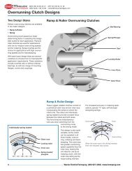
<strong>Safety</strong> <strong>Couplings</strong> Product Information<br />
T<br />
Conventional<br />
progressive<br />
characteristic<br />
System <strong>GERWAH</strong> ®<br />
degressive<br />
characteristic<br />
Figure 1: advantage of<br />
the <strong>GERWAH</strong> ® system<br />
S<br />
switching work<br />
As = f (x1) x S<br />
T max.<br />
S<br />
S =<br />
spring<br />
travel<br />
<strong>GERWAH</strong> ® backlash-<strong>free</strong> safety couplings<br />
work as spring-loaded positive couplings.<br />
The special roller or ball guides<br />
guarantee a totally backlash-<strong>free</strong> transmission<br />
of the torque in both directions of<br />
rotation (patented). The couplings are<br />
therefore especially suitable for use in<br />
speed and direction controlled drives.<br />
Uniform loading of the rollers and balls<br />
guarantees high system stiffness, which<br />
is important especially for modern servo<br />
drives. The roller guides simultaneously<br />
guarantee high reliability and switching<br />
frequencies when used with dynamic<br />
servo drives.<br />
In the event of an overload the rollers<br />
move out of the guides (fig. 2 and fig. 3).<br />
This results in an axial movement (S),<br />
which activates a proximity switch that<br />
immediately makes contact to switch off<br />
drive (fig. page 13).<br />
To avoid damage to the safety coupling,<br />
the drive must be switched off immediately<br />
after an overload. In order to reengage<br />
the safety coupling, the drive<br />
needs to be turned off. Then, the motor<br />
will be rotated at very low speed or manually.<br />
The coupling re-engages on its own<br />
in its original angular position (C-synchronous<br />
engagement) or in the next position<br />
(D-continuous engagement). The reengaging<br />
of the coupling is clearly audible<br />
and is displayed through the switch contact.<br />
After re-engaging, the safety coupling<br />
features its original disengaging torque.<br />
The drive can be switched on again after<br />
the cause of the torque overload has been<br />
removed.<br />
<strong>GERWAH</strong> ® backlash-<strong>free</strong> safety couplings<br />
have been developed especially for<br />
dynamic drives. The safety couplings work<br />
exclusively with specially selected disc<br />
springs with a pronounced degressive<br />
characteristic (see figures 1 and 4). This<br />
advantage guarantees shortest switching<br />
times and a low residual torque. The coupling<br />
disengages immediately when the<br />
predetermined amount of torque is exceeded.<br />
The torque drops immediately to a<br />
small residual value, typically 2 to 5%. The<br />
switching work required of our couplings<br />
corresponds to only a fraction of that of<br />
conventional safety couplings with progressive<br />
characteristics (see fig. 1). This<br />
is a crucial advantage because even ultrashort<br />
surges in speed are rendered harmless<br />
by the safety coupling.<br />
Figure 3:<br />
disengaged<br />
S = disengaging<br />
travel<br />
T<br />
T max<br />
T min<br />
{<br />
degressive<br />
characteristic<br />
Figure 2: engaged<br />
F = spring force<br />
STmax<br />
remaining<br />
spring force<br />
Figure 4:<br />
Spring<br />
characteristic<br />
disengaging<br />
travel<br />
STmin<br />
DIST. AUTORIZADO<br />
MEX (55) 53 63 23 31<br />
QRO (442) 1 95 72 60<br />
MTY (81) 83 54 10 18<br />
ventas@industrialmagza.com<br />
®<br />
12 info@gerwah.com • www.gerwah.com • Phone 0049-6022-22040 You Can Rely On Us! Fax 0049-6022-220411 • D-63868 Grosswallstadt
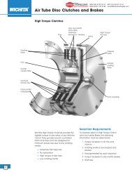
Limit Switches Application examples<br />
Proximity sensor as<br />
mechanical limit switch<br />
Application examples<br />
of <strong>GERWAH</strong> ®<br />
<strong>Safety</strong> <strong>Couplings</strong>…<br />
… in a plastic injection<br />
molding machine<br />
… im special machinery<br />
opening<br />
function<br />
switch direction<br />
disengaging travel<br />
S = ca. 1,2-2 mm<br />
<strong>GERWAH</strong> ® backlash-<strong>free</strong> safety couplings<br />
produce an axial movement (disengaging<br />
travel) of the outer cover or the ring in the<br />
event of an overload (see figure). This disengaging<br />
motion allows a proximity sensor or<br />
a mechanical limit switch to switch off the<br />
drive and simultaneously emit an acoustical<br />
or optical signal.<br />
… in a<br />
machine<br />
tool<br />
DIST. AUTORIZADO<br />
MEX (55) 53 63 23 31<br />
QRO (442) 1 95 72 60<br />
MTY (81) 83 54 10 18<br />
ventas@industrialmagza.com<br />
®<br />
info@gerwah.com • www.gerwah.com • Phone 0049-6022-22040 You Can Rely On Us! Fax 0049-6022-220411 • D-63868 Grosswallstadt<br />
13
<strong>Safety</strong> <strong>Couplings</strong> Dimensioning<br />
A good concept<br />
offers many<br />
possibilities<br />
Even large destructive forces have no<br />
chance!<br />
When determining the disengaging torque<br />
of the safety coupling, brief peaks of torque<br />
in the drive assembly as well as the machine<br />
need to be taken into account. <strong>GERWAH</strong> ®<br />
safety couplings have been developed for<br />
rapid interruption. We recommend paying<br />
special attention to the motor characteristic<br />
regarding the maximal acceleration torque.<br />
When using dynamic drives (servo motors),<br />
e.g. machine tools, we suggest to consider<br />
the influence of the moments of inertia. Since<br />
the acceleration torque in both positive and<br />
negative direction is usually much higher than<br />
T (torque)<br />
the nominal moment, the sizing of the safety<br />
coupling and the disengaging torque level<br />
needs to be based on the maximum acceleration<br />
torque.<br />
highest torque,<br />
high demolition forces<br />
will become ineffective<br />
adjusted torque of disengagement<br />
normal operating sector<br />
remaining torque (disengaged)<br />
t (time)<br />
The following values have been<br />
determined for a correct dimensioning<br />
of couplings on highly<br />
dynamic drives.<br />
Generally, the following equation applies:<br />
TA = K x Tmax x<br />
Jmach<br />
Jmot + Jmach<br />
= [Nm]<br />
Jmot<br />
Jmach<br />
Tmax<br />
TA<br />
K<br />
K<br />
K<br />
K<br />
= moment of inertia of motor<br />
= moment of inertia of machine<br />
= max. acceleration torque<br />
= cut-off (disengaging torque)<br />
of coupling<br />
= load or impact factor<br />
= 1,5 (regular movements)<br />
= 2 (irregular movements)<br />
= 2,5 - 4 (shock loads)<br />
A load/impact factor of<br />
K=1.5 - 2 should be<br />
applied to servo drives in<br />
machine tools. A higher<br />
load factor should be used<br />
for extreme applications.<br />
®<br />
DIST. AUTORIZADO<br />
MEX (55) 53 63 23 31<br />
QRO (442) 1 95 72 60<br />
MTY (81) 83 54 10 18<br />
ventas@industrialmagza.com<br />
14 info@gerwah.com • www.gerwah.com • Phone 0049-6022-22040 You Can Rely On Us! Fax 0049-6022-220411 • D-63868 Grosswallstadt
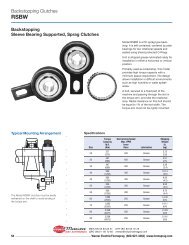
<strong>Safety</strong> <strong>Couplings</strong> Installation Instructions<br />
Types of<br />
misalignment<br />
(figure 1)<br />
axial<br />
radial<br />
= parallel<br />
angular<br />
Shaft alignment:<br />
Figure 1 shows the types of misalignment.<br />
Prior to mounting the<br />
coupling, both the coupling and<br />
the shafts must be aligned. The<br />
precision in aligning the shafts will<br />
determine the amount of reserves<br />
the coupling offers for compensation<br />
of misalignment occurring<br />
during operation. Well aligned<br />
shafts prolongue the life cycle of<br />
the coupling and help reducing the<br />
noise level of the drive.<br />
When more than one type of misalignment<br />
are present at once,<br />
each single type of misalignment<br />
must not reach the maximal value.<br />
Instead, they have to be balanced<br />
(see figure 3).<br />
Assembly:<br />
Clean and degrease shaft ends<br />
and coupling bores and check tolerances.<br />
The max. clearance between<br />
shaft and hubs must not<br />
exceed 0.03 mm.<br />
Slide coupling hubs onto shaft<br />
ends, check axial installation dimensions<br />
and tighten locking<br />
screws according to the tightening<br />
torque values shown in the technical<br />
data pages.<br />
Removal:<br />
Loosen locking screws. When<br />
necessary, use the push-off<br />
threads to loosen the backlash <strong>free</strong><br />
connection. Should the shaft/hub<br />
connection not come loose, use a<br />
rubber hammer, applying light taps.<br />
Please ask us for a detailed installation<br />
instruction or download<br />
from our website!<br />
Misalignment - DMK/B<br />
Misalignment - DMK/E<br />
size<br />
30<br />
60<br />
150<br />
300<br />
elastomer<br />
spider<br />
98<br />
98<br />
98<br />
98<br />
shorescale<br />
A<br />
A<br />
Misalignment<br />
mm<br />
radial<br />
Kr<br />
mm<br />
axial<br />
Ka 1)<br />
-0,5<br />
-0,5<br />
-0,7<br />
-0,7<br />
0,06<br />
0,10<br />
0,11<br />
0,12<br />
degree<br />
angular<br />
Kw<br />
0,9°<br />
0,9°<br />
0,9°<br />
0,9°<br />
500 98 A -1,0 0,14 0,9°<br />
1) The Ka values need to be added to the length dimension L of<br />
the selected coupling type<br />
Kr radial misalignment (%)<br />
size<br />
30<br />
60<br />
150<br />
200<br />
300<br />
500<br />
800<br />
1200<br />
100<br />
80<br />
60<br />
40<br />
20<br />
0<br />
bellow<br />
short / long<br />
4 / 6<br />
4 / 6<br />
4 / 6<br />
4 / 6<br />
4 / 6<br />
4 / 6<br />
6<br />
6<br />
75%<br />
Compensation of misalignment<br />
(figure 3)<br />
Kw<br />
excessive<br />
angular<br />
misalignment<br />
misalignment<br />
(%) will cause<br />
accelerated wear<br />
and premature<br />
failure<br />
50%<br />
25%<br />
mm<br />
axial<br />
Ka 1)<br />
0,4 / 0,5<br />
0,4 / 0,5<br />
0,4 / 0,5<br />
0,4 / 0,5<br />
0,4 / 0,5<br />
0,4 / 0,5<br />
0,5<br />
0,5<br />
0%<br />
Misalignment<br />
mm<br />
radial<br />
Kr<br />
0,1 / 0,2<br />
0,1 / 0,2<br />
0,2 / 0,2<br />
0,2 / 0,2<br />
0,2 / 0,2<br />
0,2 / 0,2<br />
0,2<br />
0,2<br />
Ka axial<br />
misalignment<br />
(%)<br />
20 30 40 60 80 100<br />
degree<br />
angular<br />
Kw<br />
1,0 /1,5°<br />
1,0 /1,5°<br />
1,0 /1,5°<br />
1,0 /1,5°<br />
1,0 /1,5°<br />
1,0 /1,5°<br />
1,0°<br />
1,0°<br />
DIST. AUTORIZADO<br />
MEX (55) 53 63 23 31<br />
QRO (442) 1 95 72 60<br />
MTY (81) 83 54 10 18<br />
ventas@industrialmagza.com<br />
®<br />
info@gerwah.com • www.gerwah.com • Phone 0049-6022-22040 You Can Rely On Us! Fax 0049-6022-220411 • D-63868 Grosswallstadt 15
Log on to<br />
www.gerwah.com<br />
for:<br />
• Complete catalogue info<br />
• 3D-CAD product drawings<br />
• Calculation software<br />
• Product and corporate news<br />
• And much more<br />
You Can Rely On Us!<br />
686/01/06.05/SBL/4c<br />
Your <strong>GERWAH</strong> ® Partner<br />
DIST. AUTORIZADO<br />
MEX (55) 53 63 23 31<br />
QRO (442) 1 95 72 60<br />
MTY (81) 83 54 10 18<br />
ventas@industrialmagza.com<br />
®<br />
<strong>GERWAH</strong> GmbH<br />
Phone (49)06022/2204-0<br />
Fax (49)06022/2204-11<br />
eMail info@gerwah.com<br />
www.gerwah.com<br />
Luetzeltaler Strasse 5a<br />
D-63868 Grosswallstadt<br />
Germany<br />
DIN EN ISO 9001<br />
PETER ® is a registered trade mark of <strong>GERWAH</strong> GmbH