Boston Gear® ORC Series Trig-O-Matic⢠Overload Release Clutches
Boston Gear® ORC Series Trig-O-Matic⢠Overload Release Clutches
Boston Gear® ORC Series Trig-O-Matic⢠Overload Release Clutches

You also want an ePaper? Increase the reach of your titles
YUMPU automatically turns print PDFs into web optimized ePapers that Google loves.
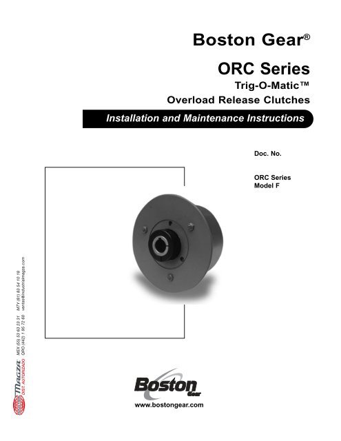
<strong>Boston</strong> Gear ®<br />
<strong>ORC</strong> <strong>Series</strong><br />
<strong>Trig</strong>-O-Matic<br />
<strong>Overload</strong> <strong>Release</strong> <strong>Clutches</strong><br />
Installation and Maintenance Instructions<br />
Doc. No.<br />
<strong>ORC</strong> <strong>Series</strong><br />
Model F<br />
®<br />
DIST. AUTORIZADO<br />
MEX (55) 53 63 23 31<br />
QRO (442) 1 95 72 60<br />
MTY (81) 83 54 10 18<br />
ventas@industrialmagza.com<br />
www.bostongear.com
MTY (81) 83 54 10 18<br />
ventas@industrialmagza.com<br />
MEX (55) 53 63 23 31<br />
QRO (442) 1 95 72 60<br />
®<br />
DIST. AUTORIZADO<br />
<strong>ORC</strong> SERIES<br />
TRIG-O-MATIC<br />
OVERLOAD RELEASE CLUTCHES –<br />
MODEL F<br />
INSTALLATION AND MAINTENANCE<br />
INSTRUCTIONS<br />
I. INTRODUCTION<br />
A. Operating Principle<br />
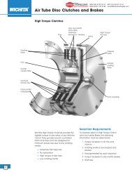
The <strong>ORC</strong> <strong>Series</strong>, Model F <strong>Overload</strong> <strong>Release</strong> Clutch<br />
consists of three basic components: the rotor, the<br />
housing assembly and the limit switch actuating<br />
mechanism assembly. The clutch rotor is keyed and<br />
secured to a shaft with a locking collar (Models FJ or<br />
FG), or with a setscrew (Model FR).<br />
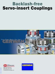
The housing assembly includes a drive pawl and a reset<br />
pawl which pivot within the clutch housing. The drive pawl<br />
is held in its engaged position by the combined<br />
compression of the drive and reset springs (Figure 1).<br />
The combined compression of these two springs<br />
determines the maximum torque which is transmitted<br />
without overload. With the clutch in its engaged position,<br />
the rotor and the housing are held together and the entire<br />
unit rotates with the drive shaft at the same speed.<br />
<strong>ORC</strong> SERIES, MODEL F CLUTCHES<br />
(Stamped 26)<br />
TABLE OF CONTENTS<br />
Drive Pawl<br />
(Stamped 9)<br />
Rotor<br />
Drive Spring<br />
Reset Spring Screw<br />
Reset Spring<br />
Reset Pawl<br />
Housing<br />
(Stamped 22)<br />
Drive Spring Screw<br />
(Stamped 8)<br />
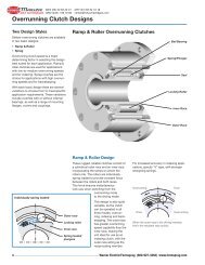
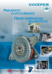
When an overload occurs, the rotor rotates from its<br />
normal position within the housing. At this instant, the<br />
combined compression of the drive and reset springs is<br />
overcome. The drive pawl is forced out of its engaged<br />
position from the rotor and as it pivots up, the reset pawl<br />
applied pressure to the top of the drive pawl holding it in<br />
contact with the rotor (Figure 2).<br />
I. Introduction<br />
A. Operating Principle<br />
B. Resetting Instructions . . . . . . . . . . . . . . . . . . . . . . . . . . . . . . . . . . . . . . . . . 2<br />
C. Torque Adjustment . . . . . . . . . . . . . . . . . . . . . . . . . . . . . . . . . . . . . . . . . . . . 2<br />
Il. Mounting Sprockets or Sheaves to Clutch<br />
A. Type T Housing . . . . . . . . . . . . . . . . . . . . . . . . . . . . . . . . . . . . . . . . . . . . . . . 3<br />
B. Type B Housing . . . . . . . . . . . . . . . . . . . . . . . . . . . . . . . . . . . . . . . . . . . . . . . 4<br />
Ill. Locating and Mounting Clutch and Couplings to Shaft<br />
A. Location . . . . . . . . . . . . . . . . . . . . . . . . . . . . . . . . . . . . . . . . . . . . . . . . . . . . 5<br />
B. Mounting the Basic Clutch . . . . . . . . . . . . . . . . . . . . . . . . . . . . . . . . . . . . . . 5<br />
C. Mounting Type “C” Flexible Coupling. . . . . . . . . . . . . . . . . . . . . . . . . . . . . 6<br />
D. Mounting Type “N” Index and Type “R” Rigid Coupling . . . . . . . . . . . . . . 7<br />
IV. Limit Switches . . . . . . . . . . . . . . . . . . . . . . . . . . . . . . . . . . . . . . . . . . . . . . . . . . 8<br />
V. General Maintenance<br />
A. Lubrication. . . . . . . . . . . . . . . . . . . . . . . . . . . . . . . . . . . . . . . . . . . . . . . . . . . 8<br />
B. Annual Inspection . . . . . . . . . . . . . . . . . . . . . . . . . . . . . . . . . . . . . . . . . . . . . 8<br />
Vl.<br />
FIGURE 1<br />
Repair Instructions<br />
A. General Disassembly . . . . . . . . . . . . . . . . . . . . . . . . . . . . . . . . . . . . . . . . . . 8<br />
B. Basic Unit Assembly. . . . . . . . . . . . . . . . . . . . . . . . . . . . . . . . . . . . . . . . . . . 9<br />
C. Torque Verification . . . . . . . . . . . . . . . . . . . . . . . . . . . . . . . . . . . . . . . . . . . 10<br />
D. Final Assembly . . . . . . . . . . . . . . . . . . . . . . . . . . . . . . . . . . . . . . . . . . . . . . 11<br />
E. Limit Switch Actuating Plate Assembly . . . . . . . . . . . . . . . . . . . . . . . . . . 11<br />
Vll. Trouble Shooting . . . . . . . . . . . . . . . . . . . . . . . . . . . . . . . . . . . . . . . . . . . . . . . 11<br />
Exploded View Drawing. . . . . . . . . . . . . . . . . . . . . . . . . . . . . . . . . . . . . . . . . . . . . . 12<br />
Catalog Numbers . . . . . . . . . . . . . . . . . . . . . . . . . . . . . . . . . . . . . . . . . . . . . . . 13, 14<br />
<strong>Boston</strong> Gear ®<br />
<strong>ORC</strong> <strong>Series</strong>, Model F 1
<strong>ORC</strong> SERIES, MODEL F CLUTCHES<br />
MTY (81) 83 54 10 18<br />
ventas@industrialmagza.com<br />
Drive Pawl<br />
(Stamped 26)<br />
(Stamped 9)<br />
Rotor<br />
Drive Spring<br />
Reset Spring Screw<br />
Reset Spring<br />
Reset Pawl<br />
Housing<br />
(Stamped 22)<br />
Drive Spring Screw<br />
(Stamped 8)<br />
FIGURE 2<br />
After one revolution, the drive pawl will automatically reengage.<br />
For a manual reset clutch the drive pawl is<br />
forced out of its engaged position from the rotor and as<br />
it pivots up, the reset pawl lifts and locks the drive pawl<br />
out of contact with the rotor. See Section B2 for<br />
resetting instructions.<br />
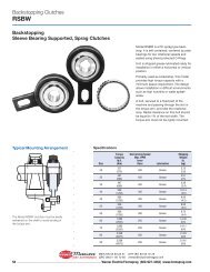
The automatic limit switch actuating mechanism<br />
assembly consists of five basic components: the<br />
actuating plate, the cam plate, the liftout buttons, the<br />
return pins and return springs. Upon overload, the<br />
rotation of the rotor causes the cam plate, which is<br />
keyed to the rotor, to exert a force on the liftout buttons<br />
forcing them to move the actuating plate axially away<br />
from the clutch housing (see Figure 3). When the clutch<br />
is re-engaged, the actuating mechanism will<br />
automatically return to its original position by the force of<br />
the return springs on the return pins.<br />
B. Resetting Instructions<br />
1. Automatic Reset To re-engage the clutch after an<br />
overload has been cleared, jog the drive until the<br />
clutch re-engages. At this point the rotor keyway will<br />
line up with the red index line on housing and the<br />
limit switch plate will retract to its original position.<br />
Actuating Plate<br />
Liftout Button<br />
2. Manual Reset<br />
a. After the overload condition has been corrected,<br />
rotate the drive until the rotor keyway is in<br />
alignment with the hole stamped 22 located on the<br />
outside diameter of the housing (see Figure 4).<br />
b. Reset the clutch by inserting a hex wrench into<br />
the reset screw shown in Figure 4, and turn the<br />
screw clockwise until the reset pawl releases the<br />
drive pawl. Refer to Table 5 for the proper wrench<br />
size.<br />
Note:<br />
Be sure not to use a powered wrench as it<br />
may cause damage to the reset pawl and/or<br />
reset spring!<br />
c. When the drive pawl enters the rotor notch, turn<br />
the wrench counterclockwise until the reset screw<br />
has stopped at its original position, which is<br />
approximately flush with the O.D. of the clutch<br />
housing. This is essential to restore the torque to<br />
its original setting.<br />
C. Torque Adjustment<br />
The clutch is supplied with a torque selector dial. This<br />
dial makes torque adjustments on the clutch possible.<br />
There are mill marks on the housing near the hole<br />
stamped 9 on the outside diameter of the housing. The<br />
mill marks have stamped values indicating a set, or<br />
minimum and maximum torque (see Figure 4A). If a<br />
drastic change in torque is desired, it may be necessary<br />
to change springs. See Section Vl for spring<br />
replacement.<br />
1. Increasing the Torque.<br />
a. Disengage the clutch.<br />
b. Turn the torque adjustment screw clockwise until it<br />
is flush with the milled depth of the desired torque<br />
setting and the red scribed lines are in line with<br />
each other.<br />
c. Reset the clutch and check its operation.<br />
Reset Spring Screw<br />
(Stamped 9)<br />
Reset Spring<br />
Reset Pawl<br />
MEX (55) 53 63 23 31<br />
QRO (442) 1 95 72 60<br />
Drive Pawl<br />
Reset Screw<br />
(Stamped 20)<br />
Access Screw<br />
(Stamped 22)<br />
®<br />
DIST. AUTORIZADO<br />
Return Spring Pin<br />
Cam Plate<br />
Return Pin<br />
Rotor<br />
Drive Spring<br />
Drive Spring Screw<br />
(Stamped 8)<br />
FIGURE 3<br />
FIGURE 4<br />
2 <strong>ORC</strong> <strong>Series</strong>, Model F <strong>Boston</strong> Gear ®
<strong>ORC</strong> SERIES, MODEL F CLUTCHES<br />
2. Decreasing the Torque.<br />
a. Make sure that the clutch is engaged.<br />
b. Turn the torque adjustment screw counterclockwise<br />
until it is flush with the milled depth of the desired<br />
torque setting and the red scribed lines are in line<br />
with each other.<br />
c. Disengage the clutch and check its operation.<br />
3. Attach sprocket or sheave to housing with mounting<br />
bolts and high collar lock washers. Refer to Table 1<br />
for recommended seating torques.<br />
4. Finish ream sprocket or sheave for dowel pins. Refer<br />
to Table 1 for dowel pin and recommended ream<br />
sizes.<br />
5. Install dowel pins to a point where they bottom in<br />
housing.<br />
Torque Adjusting Screw<br />
Square Wrench Socket<br />
Milled Depth<br />
For Max. Torque<br />
Milled Depth For<br />
Set or Min. Torque<br />
Lock Screw<br />
Reset Spring<br />
Disc<br />
TABLE 1 - MOUNTING HARDWARE INFORMATION<br />
Size<br />
Screw Dowel Seating Ream<br />
Qty.<br />
Qty.<br />
Size Size<br />
Torque Size<br />
1 1/4-20 3 1/4 1 150 in-lb .2495<br />
2 5/16-18 3 5/16 1 305 in-lb .3120<br />
3 3/8-16 4 3/8 1 545 in-lb .3745<br />
4 1/2-13 4 1/2 1 1,300 in-lb .4995<br />
5 5/8-11 6 5/8 1 2,530 in-lb .6245<br />
Reset Spring<br />
FIGURE 4A<br />
II. MOUNTING SPROCKETS OR SHEAVES<br />
TO CLUTCH<br />
A. Type T Housing<br />
1. Inspect mating pilots on clutch and sprocket or<br />
sheave for nicks or burrs and remove as required.<br />
2. Position sprocket or sheave on housing and align<br />
dowel pin holes.<br />
TABLE 2 - TYPE T MOUNTING HOLE PATTERNS<br />
Pilot Dia.<br />
Bolt +.000<br />
Size Thread Depth Circle -.002<br />
1 1 /4-20 .50 2.375 1.875<br />
2 5/16- 18 .50 3.000 2.250<br />
3 3/8-16 .62 4.125 3.250<br />
4 1/2-13 .87 5.000 3.203<br />
5 5/8-11 1.00 6.250 4.125<br />
Notes:<br />
1. Mounting bolts must be minimum 160,000 PSI tensile, Rc 36-43.<br />
2. Dowel pins must be minimum 150,000 PSI shear, Rc 50-58 core<br />
hardness.<br />
4 Tapped Holes at 90º<br />
6 Tapped Holes at 60º<br />
MTY (81) 83 54 10 18<br />
ventas@industrialmagza.com<br />
3 Tapped Holes at 120º<br />
120º Typ.<br />
20º<br />
15º<br />
20º<br />
90º Typ.<br />
14º<br />
20º<br />
60º Typ.<br />
MEX (55) 53 63 23 31<br />
QRO (442) 1 95 72 60<br />
60º<br />
Dowel Hole at 60º<br />
1 Dowel Hole at 30º<br />
30º<br />
14º<br />
1 Dowel Hole at 14º<br />
®<br />
DIST. AUTORIZADO<br />
Sizes 1 and 2 Mounting Hole Pattern<br />
Sizes 3 and 4 Mounting Hole Pattern<br />
Size 5 Mounting Hole Pattern<br />
FIGURE 5 – TYPE T STANDARD MOUNTING HOLE PATTERNS<br />
<strong>Boston</strong> Gear ®<br />
<strong>ORC</strong> <strong>Series</strong>, Model F 3
<strong>ORC</strong> SERIES, MODEL F CLUTCHES<br />
Clutch<br />
Size<br />
TABLE 3 - MINIMUM NUMBER OF TEETH OF STANDARD PLATE SPROCKETS ADAPTABLE TO TYPE T CLUTCH<br />
CHAIN SIZE AND PITCH<br />
#25 #35 #40 #41 #50 #60 #80 #100 #120 #140 #160<br />
1/4 3/8 1/2 1/2 5/8 3/4 1 1-1/4 1-1/2 1-3/4 2<br />
Pitch Pitch Pitch Pitch Pitch Pitch Pitch Pitch Pitch Pitch Pitch<br />
1 40 28 22 22 18 — — — — — —<br />
2 54 36 28 28 22 19 — — — — —<br />
3 X 45 34 36 28 25 19 — — — —<br />
4 X X 42 45 36 30 23 19 — — —<br />
5 X X X X 42 36 30 22 19 17 —<br />
Notes:<br />
1. X- On Application Only.<br />
2. For smaller sprockets, consult factory. As in most cases, a<br />
design modification can be made.<br />
B. Type B Housing<br />
A Type B clutch is a basic unit and is sold without any<br />
mounting hole arrangement. It is modified by the<br />
customer for special applications.<br />
TABLE 4 - TYPE B HOUSING DIMENSIONS<br />
F<br />
Size A B C D E +.000 G<br />
-.002<br />
1 .81 .81 1.06 .11 .31 1.500 .69<br />
2 .90 1.25 1.37 .18 .37 1.875 .81<br />
3 1.25 1.62 1.94 .29 .50 2.750 .94<br />
4 1.56 2.12 2.37 .43 .56 2.828 1.48<br />
5 1.94 2.62 3.00 .58 .69 4.000 1.62<br />
Note:<br />
The “E” Dimension on Table 4 shows pawl trunnion holes. These<br />
holes are not through holes and they should be avoided when<br />
mounting a coupling, sprocket, etc. to the clutch.<br />
"B"<br />
"C"<br />
MTY (81) 83 54 10 18<br />
ventas@industrialmagza.com<br />
"A"<br />
"D"<br />
"E" Dia. Typ.<br />
"F"<br />
Dia.<br />
"G"<br />
®<br />
DIST. AUTORIZADO<br />
MEX (55) 53 63 23 31<br />
QRO (442) 1 95 72 60<br />
FIGURE 6 – TYPE B HOUSING CONFIGURATION<br />
4 <strong>ORC</strong> <strong>Series</strong>, Model F <strong>Boston</strong> Gear ®
<strong>ORC</strong> SERIES, MODEL F CLUTCHES<br />
MTY (81) 83 54 10 18<br />
ventas@industrialmagza.com<br />
MEX (55) 53 63 23 31<br />
QRO (442) 1 95 72 60<br />
®<br />
DIST. AUTORIZADO<br />
III. LOCATING AND MOUNTING CLUTCH<br />
AND COUPLINGS TO SHAFT<br />
A. Location<br />
The clutch should always be located as close as<br />
possible to the source of an overload condition. Figures<br />
7 through 10 indicate both preferred and not preferred<br />
locations for mounting a <strong>ORC</strong> <strong>Series</strong>, Model F <strong>Overload</strong><br />
<strong>Release</strong> Clutch.<br />
Note:<br />
Clutch mounted sprockets, etc. and couplings<br />
should be positioned as close to a supporting<br />
bearing as possible to minimize overhung loads. A<br />
minimum shaft engagement of 1-1/2 times the shaft<br />
diameter is recommended for clutch and coupling<br />
flange installation.<br />
1. Direct Drives<br />
a. Figure 7 shows the preferred location for<br />
mounting in a direct drive application. The clutch<br />
is mounted on the low speed side of the reducer,<br />
and transmits power from its housing, through its<br />
rotor to the driven shaft.<br />
b. Locating the clutch as shown in Figure 8 is not<br />
preferred. Here the clutch is mounted on the<br />
high-speed side of the reducer. Generally,<br />
mounting in this manner requires the clutch to be<br />
too hypersensitive to perform satisfactorily.<br />
2. Indirect Drives<br />
a. Either location of the clutch shown in Figure 9 is<br />
preferred in indirect drive applications.<br />
b. The mounting location in Figure 10 is not<br />
preferred for the same reasons as those for<br />
Figure 8. Always consult the factory when a<br />
mounting of this type is necessary.<br />
B. Mounting Basic Clutch<br />
1. Inspect shaft and key for any nicks or burrs and<br />
remove any that may be present.<br />
2. If the clutch is a Model FJ or FG, loosen the clamp<br />
collar on the rotor of the clutch. If the clutch is a<br />
Model FR, remove the screw from the hole stamped<br />
22 outside of the housing. Make sure that the clutch<br />
is engaged where the rotor keyway is in line with the<br />
hole stamped 22.<br />
3. Position shaft key and slide clutch onto shaft.<br />
4. Align sprocket or sheave mounted to clutch with<br />
mating sprocket or sheave in drive train. Refer to<br />
installation and alignment instructions furnished with<br />
sprocket or sheave.<br />
Flexible Coupling<br />
Coupling<br />
Half<br />
<strong>Overload</strong> Clutch<br />
Motor Reducer Machine<br />
Coupling Half<br />
FIGURE 7<br />
<strong>Overload</strong> Clutch<br />
Flexible Coupling<br />
Motor Reducer Machine<br />
Driving<br />
Member<br />
<strong>Overload</strong> Clutch<br />
FIGURE 8<br />
Driven Machinery<br />
<strong>Overload</strong> Clutch<br />
Location<br />
Motor<br />
FIGURE 9<br />
Reducer<br />
Driving<br />
Member<br />
FIGURE 10<br />
<strong>Boston</strong> Gear ®<br />
<strong>ORC</strong> <strong>Series</strong>, Model F 5
<strong>ORC</strong> SERIES, MODEL F CLUTCHES<br />
TABLE 5 - WRENCH SIZE CHART<br />
Drive Reset Manual Locking<br />
Rotor Access Locking Adjustment<br />
Spring Spring Reset<br />
Collar<br />
Clutch<br />
Setscrew Screws Screw Screw<br />
Screw Screw Screw<br />
Capscrew<br />
Size<br />
Hex Hex Hex<br />
Hex Square Hex<br />
Hex Hex<br />
Wrench Wrench Wrench<br />
Wrench Wrench Wrench<br />
Wrench Wrench<br />
1 3/16 3/8 3/16 3/32 1/8 3/32 1/16 3/16<br />
2 1/4 3/8 1/4 1/8 5/32 3/32 5/64 3/16<br />
3 5/16 1/2 5/16 3/16 3/16 1/8 1/8 1/4<br />
4 5/16 1/2 3/8 1/4 5/16 1/8 1/8 5/16<br />
5 3/8 1/2 1/2 5/16 5/16 1/8 1/8 5/16<br />
MTY (81) 83 54 10 18<br />
ventas@industrialmagza.com<br />
MEX (55) 53 63 23 31<br />
QRO (442) 1 95 72 60<br />
5. For a Model FR, select the correct hex wrench from<br />
Table 5 and insert it through the hole stamped 22 in<br />
the housing. Tighten the rotor setscrew securing the<br />
clutch to the shaft.<br />
Note:<br />
Turn wrench clockwise only! Do not remove<br />
setscrew from rotor!<br />
Refer to Table 6 for recommended setscrew seating<br />
torques.<br />
6. Remove the hex wrench and replace access screw<br />
in the hole stamped 22 on the housing.<br />
7. If the clutch is a Model FJ or FG, secure the clutch to<br />
the shaft by tightening the clamp collar screw to the<br />
recommended torque in Table 7.<br />
C. Mounting Type “C” Flexible Coupling<br />
1. After the clutch has been mounted on its shaft as<br />
explained in Section lll, inspect the coupling shaft<br />
and key for any nicks or burrs and remove any that<br />
are present.<br />
2. Make sure that the coupling shaft keyway is in<br />
alignment with the clutch shaft keyway. Position shaft<br />
key and slide coupling onto the appropriate shaft.<br />
3. Slide the coupling flange onto the coupling studs.<br />
The coupling flange and adapter should be<br />
separated by a gap of 1/8”.<br />
4. Secure the coupling to drive shaft by tightening the<br />
two setscrews located in the hub of the flange. Refer<br />
to Table 8 for recommended coupling setscrew<br />
seating torques.<br />
5. Parallel Alignment<br />
a. Place a straightedge across the clutch housing<br />
and coupling flange as shown in Figure 11.<br />
b. Measure the offset around the periphery of these<br />
two components without rotating the shafts.<br />
c. If the difference in offset from any two points 180<br />
degrees apart exceeds the maximum value<br />
shown in Table 9, the shafts must be realigned.<br />
TABLE 6 - ROTOR SETSCREW SEATING TORQUES<br />
Size Screw Size Seating Torque<br />
l 10-32 36 in-lb<br />
2 1/4-28 87 in-lb<br />
3 3/8-24 290 in-lb<br />
4 1/2-20 620 in-lb<br />
5 5/8-18 1,325 in-lb<br />
TABLE 7 - CLAMP COLLAR SCREW SEATING TORQUES<br />
Size Collar Screw Seating Torque<br />
1 1/4-28 190 in-lb<br />
2 1/4-28 190 in-lb<br />
3 5/16-24 435 in-lb<br />
4 3/8-24 750 in-lb<br />
5 3/8-24 750 in-lb<br />
TABLE 8- COUPLING SETSCREW SEATING TORQUES<br />
Size Setscrew Size Seating Torque<br />
1 5/16-18 165 in-lb<br />
2 3/8-16 290 in-lb<br />
3 3/8-16 290 in-lb<br />
4 1/2-13 620 in-lb<br />
5 1/2-13 620 in-lb<br />
Straightedge<br />
1 2 3 4 5<br />
OFFSET<br />
®<br />
DIST. AUTORIZADO<br />
FIGURE 11<br />
6 <strong>ORC</strong> <strong>Series</strong>, Model F <strong>Boston</strong> Gear ®
<strong>ORC</strong> SERIES, MODEL F CLUTCHES<br />
MTY (81) 83 54 10 18<br />
ventas@industrialmagza.com<br />
MEX (55) 53 63 23 31<br />
QRO (442) 1 95 72 60<br />
6. Angular Alignment<br />
a. Measure the gap around the periphery between<br />
the coupling flange and the clutch housing without<br />
rotating the shafts. Refer to Figure 12.<br />
b. If the difference between any two points 180<br />
degrees apart exceeds the maximum angular<br />
misalignment shown in Table 9, the shafts must<br />
be realigned.<br />
c. If a correction is required to satisfy angular<br />
alignment requirements, then recheck the parallel<br />
alignment.<br />
TABLE 9 - TYPE “C” MISALIGNMENT<br />
Size<br />
Maximum Allowable Misalignment<br />
Parallel<br />
Angular<br />
1 .012” .074”<br />
2 .015” .091”<br />
3 .016” .102”<br />
4 .027” .159”<br />
5 .031” .183”<br />
Feeler Gage<br />
FIGURE 12<br />
D. Mounting the “N” Index Coupling and Type “R”<br />
Rigid Coupling<br />
1. After the clutch has been mounted as explained in<br />
Section lll, inspect mating pilots of clutch and<br />
coupling for any nicks or burrs and remove any that<br />
are present.<br />
2. Inspect coupling shaft and key for any nicks or burrs<br />
and remove any that are present.<br />
3. In the case of a “R”, make sure that the coupling<br />
shaft keyway is in alignment with the clutch shaft<br />
keyway. Position the shaft key and slide the coupling<br />
flange onto the shaft.<br />
4. Slide the coupling onto the clutch housing making<br />
sure that the coupling pilot fits into the housing pilot<br />
and that the mounting holes are aligned. In the case<br />
of a “N” index coupling, make sure that the desired<br />
mounting slots are aligned with the clutch housing<br />
mounting holes.<br />
5. Secure the coupling to the drive shaft by tightening<br />
the two setscrews located in the hub of the flange.<br />
Refer to Table 8 for recommended coupling setscrew<br />
seating torques.<br />
6. Parallel Alignment<br />
a. Place a straightedge across the clutch housing<br />
and coupling flange as shown in Figure 11.<br />
b. Measure the offset around the periphery of these<br />
two components without rotating the shafts.<br />
c. The shafts must be aligned until no offset exists or<br />
is equal at all points around the periphery.<br />
7. Angular Alignment<br />
a. Measure the gap around the periphery between<br />
the coupling flange and clutch housing without<br />
rotating the shafts. Refer to Figure 12.<br />
b. The shafts must be aligned until no gap exists or<br />
is equal at all points around the periphery.<br />
c. If a correction is required to satisfy angular<br />
alignment requirements, then recheck the parallel<br />
alignment.<br />
Note:<br />
The Type “N” and “R” coupling connection is<br />
rigid and does not allow for forgiveness of<br />
parallel or angular misalignment. To eliminate<br />
unnecessary bearing loads, both shafts must be<br />
in near perfect alignment.<br />
8. Loosen the coupling setscrews and attach coupling<br />
to clutch with hex head bolts and flat washers. Refer<br />
to Table 10 for recommended bolt seating torques.<br />
Secure coupling to drive shaft by tightening the<br />
setscrews (refer to Table 8).<br />
TABLE 10 - COUPLING MOUNTING BOLT SEATING TORQUES<br />
Size Bolt Size Seating Torque<br />
1 5/16-18 170 in-lb<br />
2 3/8-16 300 in-lb<br />
3 1/2-13 750 in-lb<br />
4 5/8-11 1,270 in-lb<br />
5 5/8-11 1,270 in-lb<br />
®<br />
DIST. AUTORIZADO<br />
<strong>Boston</strong> Gear ®<br />
<strong>ORC</strong> <strong>Series</strong>, Model F 7
<strong>ORC</strong> SERIES, MODEL F CLUTCHES<br />
IV. LIMIT SWITCHES<br />
Figure 13 shows a typical use of a limit switch to detect an<br />
overload condition. The switch should be able to operate<br />
within the travel of the limit switch plate. Upon overload, the<br />
limit switch plate will move to actuate the limit switch and<br />
shut down the drive.<br />
The switch should be wired in parallel with a jog circuit so<br />
that the drive can be indexed for re-engagement. After the<br />
clutch has been re-engaged, the limit switch will be reset<br />
and the drive can be restarted.<br />
V. GENERAL MAINTENANCE<br />
A. Lubrication<br />
The <strong>ORC</strong> <strong>Series</strong>, Model F <strong>Overload</strong> <strong>Release</strong> Clutch is<br />
prelubricated at the factory and is also equipped with a<br />
grease pack fitting. For optimum performance and wear<br />
resistance it is suggested that the clutch be lubricated<br />
with a Bentone type, NLGI grade 0 grease. The<br />
lubrication schedule should be in accordance with good<br />
operating practices for the equipment on which the<br />
clutch is mounted. The clutch is also supplied with a<br />
grease relief fitting. When there is enough grease in the<br />
clutch any excess grease will be extruded through the<br />
relief fitting.<br />
B. Annual Inspection<br />
The <strong>ORC</strong> <strong>Series</strong>, Model F <strong>Overload</strong> <strong>Release</strong> Clutch is<br />
constructed of heavy duty materials. Under reasonably<br />
clean conditions the unit will operate with a minimum of<br />
maintenance. A scheduled annual inspection of<br />
bearings, pawls, rotor, springs, actuating plate, cam<br />
plate and other internal components is suggested.<br />
However, the actual frequency should be in accordance<br />
with good operating practices for the equipment on<br />
which the clutch is installed.<br />
VI. REPAIR INSTRUCTIONS<br />
A. General Disassembly<br />
1. All item numbers in parenthesis will refer to clutch<br />
exploded view drawing and parts identification table.<br />
2. Place the clutch preferably in a three-jaw chuck with<br />
the actuating plate facing up.<br />
3. Remove the return pin nuts (32) from the return pins.<br />
This is accomplished by holding the return pin steady<br />
with a screwdriver while turning the return pin nut<br />
counter-clockwise with a box or open end wrench.<br />
4. Lift off the actuating plate (26) from the clutch.<br />
5. There are two locking screws (24) located on the<br />
face of the cover which lock down the reset spring<br />
screw (15) and the drive spring screw (20). Loosen<br />
these screws to relieve the pressure on the drive<br />
spring screw and reset spring screw.<br />
6. Turn the reset spring screw (15) counter-clockwise to<br />
relieve the compression on the reset spring (18).<br />
7. Remove the sealing wax from the drive spring screw<br />
(20) and turn the screw counterclockwise to relieve<br />
the compression on the drive spring (17).<br />
8. Remove the cam plate (36) from the face of the<br />
cover (8). Be sure not to pry on the outer edge of the<br />
cover as the outer lip may break (see Figure 14).<br />
MTY (81) 83 54 10 18<br />
ventas@industrialmagza.com<br />
LIMIT<br />
SWITCH<br />
RECOMMENDED<br />
PROXIMITY<br />
SWITCH<br />
TRACKING RADIUS<br />
START<br />
Clutch Movement Tracking Radius<br />
Size Inch Inch<br />
1 .18 2.38<br />
2 .18 3.25<br />
3 .18 4.18<br />
4 .18 5.25<br />
5 .18 6.25<br />
MEX (55) 53 63 23 31<br />
QRO (442) 1 95 72 60<br />
®<br />
DIST. AUTORIZADO<br />
LIMIT SWITCH<br />
PLATE MOVEMENT<br />
JOG<br />
STOP<br />
TO MOTOR<br />
NOTE:<br />
The limit switch actuating plate<br />
supplied with the Model F<br />
<strong>Overload</strong> <strong>Release</strong> Clutch is<br />
furnished with a mild steel plate,<br />
suitable for use with a proximity<br />
sensor switch and has a 1.0<br />
Normal Sensor Range.<br />
FIGURE 13 – LIMIT SWITCH LAYOUT<br />
8 <strong>ORC</strong> <strong>Series</strong>, Model F <strong>Boston</strong> Gear ®
<strong>ORC</strong> SERIES, MODEL F CLUTCHES<br />
MTY (81) 83 54 10 18<br />
ventas@industrialmagza.com<br />
MEX (55) 53 63 23 31<br />
QRO (442) 1 95 72 60<br />
Pry Bar<br />
Escessive Force<br />
May Break Outer<br />
Lip of Cover<br />
Cam Plate<br />
FIGURE 14<br />
9. Remove the Woodruff key (37).<br />
Cover<br />
Pry Bar<br />
Housing<br />
Excessive Force<br />
May Break Inner<br />
Pilot of Cover<br />
10. Remove the snap ring (33) from the rotor (12).<br />
11. Remove the cover screws (23).<br />
12. Pry off the cover (8). Use care not to break the<br />
inner pilot of the cover (see Figure 14).<br />
13. Remove the return pin snap rings (33) from the face<br />
of the cover (8), then remove the return pins (31)<br />
and the return pin springs (34).<br />
14. Remove the reset spring screw (15) and take out<br />
the reset spring (18), and the ball thrust (19)<br />
through the hole stamped 9.<br />
15. Remove the reset pawl (11) by simply lifting out.<br />
16. Remove the drive pawl (10) and the drive spring<br />
(17). This will require a little more effort because of<br />
the slight pressure on the drive spring.<br />
17. Press out the rotor (12).<br />
18. If clutch is manual reset, remove the reset screw<br />
(see Figure 4A) by turning clockwise into the<br />
housing.<br />
19. Inspect hardened bushings (3) in housing (1 ) and<br />
cover (8) for excessive wear (sizes 2 through 5<br />
only).<br />
20. Replace any worn or broken parts.<br />
B. Basic Unit Assembly<br />
1. If clutch is manual reset, install the reset screw from<br />
the inside of the housing turning counterclockwise<br />
until the reset screw pin stops the screw from turning.<br />
2. Press the rotor (12) into the housing bearing. If the<br />
rotor is a Model FJ or Model FG, press the shorter<br />
end of the rotor into the housing bearing. If the rotor<br />
is a Style 2, then press the sawcut section of the<br />
rotor into the housing bearing.<br />
3. This step is for manual reset only. Go to next step for<br />
automatic reset. Install the drive pawl (10) into the<br />
appropriate hole in the housing (1), and the reset<br />
pawl (11) into its appropriate hole in the housing.<br />
Check the fit of the reset pawl into the notch of the<br />
drive pawl with the clutch disengaged. The reset<br />
pawl should fit approximately one-third of the way<br />
into the notch. Grinding the nose of the reset pawl<br />
may be necessary to obtain the proper fit.<br />
4. The drive pawl (10) and the drive spring (17) will<br />
have to be installed simultaneously. If a drastic<br />
change in torque is desired, use this step to change<br />
the drive spring. Place one end of the drive spring<br />
over the drive spring thrust washer. Insert the knob of<br />
the drive pawl into the other end of the drive spring.<br />
Insert the trunnion of the drive pawl into the<br />
hardened bushing in the housing, while the nose of<br />
the drive pawl fits into the notch of the rotor (12).<br />
Install the reset pawl (11) into its appropriate hole in<br />
the housing (see Figure 15).<br />
5. Coat the inside of the housing and all components<br />
with a quality all-purpose grease. A Bentone type,<br />
NLGI grade 0 or equivalent is recommended.<br />
10<br />
12<br />
Reset Screw Flush With Surface of Housing<br />
15<br />
16<br />
11<br />
17<br />
20<br />
5<br />
1<br />
Drive Screw Flush<br />
FIGURE 15 – CLUTCH INTERNAL COMPONENTS<br />
®<br />
DIST. AUTORIZADO<br />
<strong>Boston</strong> Gear ®<br />
<strong>ORC</strong> <strong>Series</strong>, Model F 9
<strong>ORC</strong> SERIES, MODEL F CLUTCHES<br />
MTY (81) 83 54 10 18<br />
ventas@industrialmagza.com<br />
MEX (55) 53 63 23 31<br />
QRO (442) 1 95 72 60<br />
6. Insert the reset spring disc (16) inside the reset<br />
spring screw (15). Apply grease to the surface of the<br />
disc.<br />
7. If a drastic change in torque is desired, use this step<br />
to change the reset spring. Place the reset spring<br />
(18) on the surface of the reset spring disc. Apply<br />
grease to the end of the ball thrust (19) and insert<br />
ball thrust into the reset spring.<br />
8. Apply grease to the threads of the reset spring screw<br />
(15) and insert the assembly of the reset spring<br />
screw, reset spring disc 16), reset spring (18), and<br />
ball thrust (19) through the hole stamped 9 on the<br />
housing. Tighten the reset spring screw until it is<br />
flush with the surface of the housing (see Figure 15).<br />
9. Fill the entire housing cavity with grease to ensure a<br />
proper grease packing.<br />
10. Install a return pin spring (34) over each return pin<br />
(31). Locate the return pin holes in the cover by<br />
placing the cover over the housing assembly.<br />
11.Once the return pin hole locations have been<br />
established, insert the return pins and springs<br />
through the appropriate holes in the cover.<br />
12. Install a snap ring (33) into the groove on the end of<br />
each return pin (31).<br />
13.Press the cover assembly onto the housing<br />
assembly. Make sure that the trunnion holes and the<br />
cover screw holes line up.<br />
14 Install the cover screws (23) and tighten to the<br />
suggested torques in Table 12.<br />
TABLE 12 - COVER SCREW SEATING TORQUES<br />
Clutch Screw Seating<br />
Qty.<br />
Size Size<br />
Torque<br />
1 1/4-20 3 100 in-lb<br />
2 5/16-18 3 200 in-lb<br />
3 3/8-16 3 350 in-lb<br />
4 1/2-13 4 850 in-lb<br />
5 5/8-11 4 1,700 in-lb<br />
15. Install the rotor snap ring (38) into the groove of the<br />
rotor. The unit is now ready for testing.<br />
C. Torque Verification<br />
1. Place the clutch in a chuck or vise with the cover<br />
facing upward.<br />
2. Insert the appropriate size arbor and key into rotor<br />
(see Figure 16).<br />
3. If the unit is a Model FJ or FG, place the locking<br />
collar (13) onto the sawcut section of the rotor and<br />
tighten. If the clutch is a Model FR, remove the<br />
access screw from the hole stamped 22 on the<br />
housing. Insert hex wrench through this hole and<br />
tighten the rotor setscrew. Replace the access<br />
screw.<br />
Vice or Chuck Jaws<br />
Arbor<br />
Collar<br />
FIGURE 16<br />
Model F Clutch<br />
Torque Wrench<br />
4. Turn the drive spring screw (20) clockwise until it is<br />
flush with the surface of the housing (see Figure 15).<br />
5. The clutch is supplied with a torque selector dial. The<br />
torque selector dial is the two or three mill marks<br />
located at the hole stamped 9 on the housing. If a<br />
drive spring (17), reset spring (18), and/or a reset<br />
spring screw (15) were replaced, chances are that<br />
the stamped torque values on the dial are no longer<br />
valid. It may be necessary to grind the old numbers<br />
off and to stamp new numbers.<br />
6. Tighten the reset spring screw (15) until it reaches<br />
the limit stop pin (4). This will be the maximum torque<br />
position. If the maximum torque is not desired,<br />
tighten the reset spring screw to one of the locations<br />
on the torque selector dial.<br />
7. Disengage the clutch with a torque wrench. Fine tune<br />
the torque by turning the drive spring screw (20) until<br />
the desired release torque is obtained.<br />
8. Once the desired release torque is obtained, tighten<br />
the locking screws (24) located over the drive spring<br />
and reset spring screws to ensure that they will not<br />
move.<br />
®<br />
DIST. AUTORIZADO<br />
10 <strong>ORC</strong> <strong>Series</strong>, Model F <strong>Boston</strong> Gear ®
<strong>ORC</strong> SERIES, MODEL F CLUTCHES<br />
MTY (81) 83 54 10 18<br />
ventas@industrialmagza.com<br />
MEX (55) 53 63 23 31<br />
QRO (442) 1 95 72 60<br />
®<br />
DIST. AUTORIZADO<br />
D. Final Assembly<br />
1. Remove the torque wrench, locking collar (for Model<br />
FJ and FG), and arbor. For Model FR, remove the<br />
access screw from the hole stamped 22 on the<br />
housing, loosen the rotor setscrew and replace<br />
access screw. Then remove the clutch from chuck or<br />
vise.<br />
2. Apply a thin coat of grease to the “O”-ring (39) and<br />
place it into groove on the outer edge of the cover.<br />
Be sure not to twist the “O”-ring.<br />
3. Insert the Woodruff key (37) into the keyslot of the<br />
rotor. The Woodruff key may require a gentle tap with<br />
a hammer.<br />
4. Press the cam plate (36) onto the rotor.<br />
5. Place the actuating plate (26) over the rotor and<br />
cover. There is an arrow on the actuating plate which<br />
should point to the keyway in the rotor when properly<br />
installed. The return pins should fit through the<br />
proper holes in the actuating plate (see Figure 17).<br />
6. Install the return pin nuts (32) onto the end of the<br />
return pins. This is accomplished by holding the<br />
return pin steady with a screwdriver while turning the<br />
return pin nut clockwise with a box or open end<br />
wrench.<br />
7. If the clutch is a Model FJ or FG, install the locking<br />
collar (13) onto the sawcut section of the rotor. Do<br />
not tighten the collar until the clutch is installed on<br />
the shaft. Refer to Section lll for installation of the<br />
basic clutch.<br />
E. Limit Switch Actuating Plate Assembly<br />
(Sizes 1 and 5)<br />
1. Push liftout buttons (27) through appropriate holes in<br />
the actuating plate (26). Secure each liftout button<br />
with a snap ring (28).<br />
2. Push holdout buttons (29) through appropriate holes<br />
in the actuating plate (26). Secure each holdout<br />
button with a snap ring (30).<br />
CAUTION!<br />
Rotating equipment is potentially dangerous and could<br />
cause injury or damage if not properly protected. Follow all<br />
applicable codes and regulations.<br />
In accordance with our established policy to constantly<br />
improve our products, the specifications contained herein<br />
are subject to change without notice.<br />
Arrow on Actuating Plate<br />
Lines Up With Rotor Keyway<br />
FIGURE 17 – KEYWAY LOCATION<br />
CHECK LOAD<br />
INCREASED CLUTCH TORQUE SETTING<br />
CHECK PAWL AND ROTOR FOR<br />
EXCESSIVE WEAR<br />
CHECK ACTUATING PLATE LIFTOUT/<br />
HOLDOUT BUTTONS FOR EXCESSIVE WEAR<br />
EXCESSIVE CLUTCH<br />
OVERLOADING<br />
X X X<br />
EXCESSIVE CLUTCH<br />
BACKLASH<br />
X X X<br />
LIMITED ACTUATING<br />
PLATE MOVEMENT<br />
X<br />
CLUTCH WILL NOT<br />
RE-ENGAGE<br />
X<br />
PROXIMITY SENSOR<br />
DETECTING X X<br />
FALSE OVERLOADS<br />
RELOCATE OR ADJUST PROXIMITY SENSOR<br />
JOG CLUTCH INTO RE-ENGAGEMENT.<br />
X<br />
<strong>Boston</strong> Gear ®<br />
<strong>ORC</strong> <strong>Series</strong>, Model F 11
<strong>ORC</strong> SERIES, MODEL F CLUTCHES<br />
®<br />
DIST. AUTORIZADO<br />
MEX (55) 53 63 23 31<br />
QRO (442) 1 95 72 60<br />
MTY (81) 83 54 10 18<br />
ventas@industrialmagza.com<br />
<strong>ORC</strong> SERIES, MODEL F<br />
12 <strong>ORC</strong> <strong>Series</strong>, Model F <strong>Boston</strong> Gear ®
MTY (81) 83 54 10 18<br />
ventas@industrialmagza.com<br />
MEX (55) 53 63 23 31<br />
QRO (442) 1 95 72 60<br />
®<br />
DIST. AUTORIZADO<br />
<strong>ORC</strong> SERIES, MODEL F CLUTCHES<br />
Key No. Name Size 1 (Qty. ) Size 2 (Qty.) Size 3 (Qty.) Size 4 (Qty.) Size 5 (Qty.)<br />
T Housing Ass’y., or *** 711257-XXX (1) 711148-XXX (1) 711180-XXX (1) 711223-XXX (1) 711238-XXX (1)<br />
1 B Housing Ass’y, or *** 711258-XXX (1) 711149-XXX (1) 711181-XXX (1) 711224-XXX (1) 711239-XXX (1)<br />
C Housing Ass'y.,or *** 711259-XXX (1) 711150-XXX (1) 711182-XXX (1) 711225-XXX (1) 711240-XXX (1)<br />
N/R Housing Ass’y.*** 711260-XXX (1) 711151 -XXX (1) 711183-XXX (1) 711226-XXX (1) 711241-XXX<br />
2 Housing Bearing 039273-041 (1) 039273-043 (1) 039273-044 (2) 039273-038 (1) 711900-006 (1)<br />
3 Hardened Bushing — 730634-002 (2) 730634-003 (2) 730634-004 (2) 730634-005 (2)<br />
4 Limit Stop Pin 730422-001 (1) 730422-001 (1) 730422-002 (1) 730422-002 (1) 730422-003 (1)<br />
5 Access Screws 040940-031 (2) 040940-042 (2) 074102-003 (2) 074102-078 (2) 074102-078 (2)<br />
6 Grease Fitting 034186-029 (1) 034186-029 (1) 034186-029 (1) 034186-029 (1) 034186-029 (1)<br />
7 Relief Fitting 034186-028 (1) 034186-028 (1) 034186-028 (1) 034186-028 (1) 034186-028 (1)<br />
8 Cover Assembly 711263-001 (1) 710487-001 (1) 711103-001 (1) 711220-001 (1) 711244-001 (1)<br />
9 Cover Bearing 039273-040 (1) 039273-042 (1) 039273-045 (1) 039273-038 (1) 711900-005 (1)<br />
3 Hardened Bushing — 730634-002 (2) 730634-003 (2) 730634-004 (2) 730634-005 (2)<br />
Drive Pawl, or 730429-001 (1) 730430-001 (1) 730431-001 (1) 730432-001 (1) 730433-001 (1)<br />
10 Drive Pawl L.H., or 730468-001 (1) 730549-001 (1) 730551-001 (1) 730553-001 (1) 730555-001 (1)<br />
Drive Pawl R.H. 730649-001 (1) 730550-001 (1) 730552-001 (1) 730554-001 (1) 730556-001 (1)<br />
11 Reset Pawl** 730637-XXX (1) 730638-XXX (1) 730639-XXX (1) 730370-XXX (1) 730371-XXX (1)<br />
Rotor Model FJ, or 730470-001 (1) 730471-001 (1) 730472-001 (1) 730473-001 (1) 730474-001 (1)<br />
Rotor Model FJ, L.H., or 730517-001 (1) 730518-001 (1) 730519-001 (1) 730520-001 (1) 730521-001 (1)<br />
Rotor Model FJ, R.H,. or 730522-001 (1) 730523-001 (1) 730524-001 (1) 730525-001 (1) 730526-001 (1)<br />
Rotor Model FG, or 730475-001 (1) 730476-001 (1) 730477-001 (1) 730478-001 (1) 730479-001 (1)<br />
12 Rotor Model FG, L.H., or 730527-001 (1) 730528-001 (1) 730529-001 (1) 730530-001 (1) 730531-001 (1)<br />
Rotor Model FG, R.H., or 730532-001 (1) 730533-001 (1) 730534-001 (1) 730535-001 (1) 730536-001 (1)<br />
Rotor Model FR, or 710357-001 (1) 710357-002 (1) 710357-003 (1) 710357-004 (1) 710357-005 (1)<br />
Rotor Model FR, L.H., or 710968-001 (1) 710968-002 (1) 710968-003 (1) 710968-004 (1) 710968-005 (1)<br />
Rotor Model FR, R.H., or 710969-001 (1) 710969-002 (1) 710969-003 (1) 710969-004 (1) 710969-005 (1)<br />
13 Locking Collar (FJ & FG) 730094-013 (1) 730094-014 (1) 730094-015 (1) 730094-016 (1) 730094-017 (1)<br />
14 Rotor Setscrew (FR) 043243-012 (1) 043243-022 (1) 043243-041 (1) * (1) 043243-058 (1)<br />
15 Reset Spring Screw 730382-001 (1) 730382-002 (1) 730382-003 (1) 730382-004 (1) 730382-005 (1)<br />
16 Reset Spring Disc 730383-001 (1) 730383-002 (1) 730383-003 (1) 730383-004 (1) 730383-005 (1)<br />
A-Drive Spring, or 730385-001 (1) 730385-007 (1) 730385-014 (1) 730385-020 (1) 730385-026 (1)<br />
17 B-Drive Spring, or 730385-002 (1) 730385-008 (1) 730385-015 (1) 730385-021 (1) 730385-027 (1)<br />
C-Drive Spring 730385-003 (1) 730385-009 (1) 730385-016 (1) 730385-022 (1) 730385-028 (1)<br />
A-Reset Spring, or 730385-004 (1) 730385-010 (1) 730385-017 (1) 730385-023 (1) 730385-029 (1)<br />
18<br />
B-Reset Spring, or 730385-005 (1) 730385-011 (1) 730385-018 (1) 730385-024 (1) 730385-030 (1)<br />
C-Reset Spring, or 730385-006 (1) 730385-012 (1) 730385-019 (1) 730385-025 (1) 730385-031 (1)<br />
D-Reset Spring — 730385-013 (1) — — —<br />
19 Ball Thrust — 730386-001 (1) 730386-002 (1) 730386-003 (1) 730387-001 (2)<br />
20 Drive Spring Screw 730379-001 (1) 730379-002 (1) 730379-003 (1) 730379-003 (1) 730380-001 (1)<br />
21 Drive Spring Washer 730388-001 (1) 730388-002 (1) 730388-003 (1) 730388-003 (1) 730388-004 (1)<br />
22 Snap Ring — 040682-029 (1) 040682-030 (1) 040682-030 (1) 040682-030 (1)<br />
23 Cover Screw 041315-048 (3) 041315-062 (3) 041315-077 (3) 041315-106 (3) 041315-121 (3)<br />
24 Locking Screw 074102-015 (2) 074102-015 (2) 074102-031 (2) 074102-031 (2) 074102-027 (2)<br />
25 Locking Insert 730389-001 (2) 730389-001 (2) 730389-002 (2) 730389-002 (2) 730389-003 (2)<br />
Actuating Plate Ass'y. 710307-001 (1) 710308-001 (1) 710309-001 (1) 710310-001 (1) 710311-001 (1)<br />
26 Actuating Plate 730485-001 (1) 730486-001 (1) 730487-001 (1) 730488-001 (1) 730489-001 (1)<br />
27 Liftout Button 730490-001 (3) — — — 730490-001 (4)<br />
28 Snap Ring 040682-030 (3) — — — 040682-030 (4)<br />
29 Holdout Button 730491-001 (3) — — — 730491-001 (3)<br />
30 Snap Ring 040682-035 (3) — — — 040682-035 (3)<br />
Return Pin Ass’y. 710312-001 (3) 710313-001 (3) 710313-001 (3) 710314-001 (4) 710315-001 (4)<br />
31 Return Pin 730498-001 (3) 730498-001 (3) 730498-001 (3) 730498-002 (4) 730498-002 (4)<br />
32 Return Pin Nut 730499-001 (3) 730499-001 (3) 730499-001 (3) 730499-002 (4) 730499-002 (4)<br />
33 Snap Ring 040682-036 (3) 040682-036 (3) 040682-036 (3) 040682-030 (4) 040682-030 (4)<br />
34 Return Pin Spring 730500-001 (3) 730500-001 (3) 730500-001 (3) 730500-002 (4) 730500-002 (4)<br />
35 Return Pin Washer 730501-001 (3) — — — 730501-002 (4)<br />
Cam Plate Ass'y. 710316-001 (1) 710317-001 (1) 710318-001 (1) 710319-001 (1) 710320-001 (1)<br />
36 Cam Plate 730502-001 (1) 730503-001 (1) 730504-001 (1) 730505-001 (1) 730506-001 (1)<br />
37 Woodruff Key 730263-001 (1) 730263-001 (1) 730263-002 (1) 730263-002 (1) 730263-003 (1)<br />
38 Snap Ring 040682-037 (1) 040682-038 (1) 040682-039 (1) — 040682-040 (1)<br />
39 O- Ring 023750-056 (1) 023750-336 (1) 023750-096 (1) 023750-163 (1) 023750-098 (1)<br />
C Coupling Ass’y. 710296-001 (1) 710297-001 (1) 710298-001 (1) 710299-001 (1) 710300-001 (1)<br />
Coupling Bushing 730275-001 (3) 730275-002 (3) 730275-003 (4) 730275-004 (4) —<br />
Setscrew 040940-041 (2) 040940-003 (2) 040940-003 (2) 040940-067 (2) —<br />
Coupling Pin 730278-001 (3) 730278-002 (3) 730278-003 (4) 730278-004 (4) —<br />
N/C Coupling Ass’y. 710301-001 (1) 710302-001 (1) 710303-001 (1) 710334-001 (1) O/A<br />
Mounting Screw 074118-062 (3) 074118-077 (3) 074118-093 (4) 074118-110 (4) —<br />
Flat Washer 074117-004 (3) 074117-006 (3) 074117-013 (4) 074117-013 (4) —<br />
Setscrew 040940-041 (2) 040940-003 (2) 040940-003 (2) 040940-067 (2) —<br />
Manual Reset Screw Ass’y. 710356-001 (1) 710356-002 (1) 710356-003 (1) 710356-004 (1) 710356-005 (1)<br />
<strong>Boston</strong> Gear ®<br />
PART IDENTIFICATION - <strong>ORC</strong> SERIES, MODEL F<br />
*Dependent upon bore - consult the factory. **-001 Automatic; -003 Manual ***-001 Automatic; -002 Manual<br />
Note: Please include clutch catalog number when ordering any spare parts.<br />
<strong>ORC</strong> <strong>Series</strong>, Model F 13
<strong>ORC</strong> SERIES, MODEL F CLUTCHES<br />
<strong>ORC</strong> MODEL F SERIES PART NUMBERING SYSTEM<br />
<strong>ORC</strong> 2 FG C - L P16 - P16<br />
<strong>Series</strong> Model Type Torque Range Coupling Bore (Type C, N or R Only)<br />
<strong>Overload</strong> FJ = Model F, B = Basic L = Light P = Bored to Size (in 1/16”)<br />
<strong>Release</strong> Clutch Full Available C = Flexible Coupling M = Medium M = Metric Bored to Size (mm)<br />
Shaft Length N = Indexing Coupling H = Heavy (Leave Blank for Non-Coupled Units)<br />
FG = Model F,<br />
R = Rigid Coupling<br />
Size Limited Available T = Sprocket Mount<br />
1 Shaft Length<br />
2 FR = Model F, Unit Bore<br />
3 Overall Limited P = Bored to Size (in 1/16”)<br />
4 Space M = Metric Bored to Size (mm)<br />
5<br />
®<br />
DIST. AUTORIZADO<br />
MEX (55) 53 63 23 31<br />
QRO (442) 1 95 72 60<br />
MTY (81) 83 54 10 18<br />
ventas@industrialmagza.com<br />
14 <strong>ORC</strong> <strong>Series</strong>, Model F <strong>Boston</strong> Gear ®
<strong>ORC</strong> SERIES, MODEL F CLUTCHES<br />
COUPLINGS<br />
<strong>Boston</strong> Gear<br />
14 Hayward Street<br />
Quincy, MA 02171<br />
Tel 617.328.3300<br />
fax 617.479.6238<br />
www.bostongear.com<br />
CLUTCHES<br />
<strong>Boston</strong> Gear<br />
14 Hayward Street<br />
Quincy, MA 02171<br />
Tel 617.328.3300<br />
fax 617.479.6238<br />
www.bostongear.com<br />
®<br />
DIST. AUTORIZADO<br />
MEX (55) 53 63 23 31<br />
QRO (442) 1 95 72 60<br />
MTY (81) 83 54 10 18<br />
ventas@industrialmagza.com<br />
<strong>Boston</strong> Gear<br />
14 Hayward Street<br />
Quincy, MA 02171<br />
tel 617.328.3300<br />
fax 617.479.6238<br />
http://www.bostgear.com<br />
email info@bosgear.com<br />
<strong>Boston</strong> Gear ®<br />
<strong>ORC</strong> <strong>Series</strong>, Model F 15