Installation instructions for the TBLZ 2-3-41-2 and TBLZ 2 ... - Swegon
Installation instructions for the TBLZ 2-3-41-2 and TBLZ 2 ... - Swegon
Installation instructions for the TBLZ 2-3-41-2 and TBLZ 2 ... - Swegon

Create successful ePaper yourself
Turn your PDF publications into a flip-book with our unique Google optimized e-Paper software.
GB.ModemIN.101217<br />
<strong>Installation</strong> <strong>instructions</strong> <strong>for</strong> <strong>the</strong><br />
<strong>TBLZ</strong> 2-3-<strong>41</strong>-2 <strong>and</strong> <strong>TBLZ</strong> 2-3-<strong>41</strong>-1 modem<br />
GOLD<br />
1. General<br />
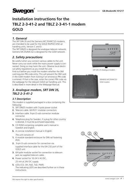
The SRT DIN 35 <strong>and</strong> <strong>the</strong> Siemens MC35i/MC52i modems<br />
are intended to be used <strong>for</strong> <strong>the</strong> GOLD RX/PX/CX/SD air<br />
h<strong>and</strong>ling units, Version C <strong>and</strong> D.<br />
The SRT DIN35 is designed <strong>the</strong> analogue telecom network;<br />
Siemens MC35i/MC52i is designed <strong>for</strong> <strong>the</strong> GSM network.<br />
2. Safety precautions<br />
Be careful when you connect various cables to <strong>the</strong> unit.<br />
Never carry out work while <strong>the</strong> mains power supply is connected.<br />
Doing so may harm <strong>the</strong> unit. Observe local electrical<br />
safety regulations as you install <strong>the</strong> unit.<br />
Find out be<strong>for</strong>e you install <strong>the</strong> modem whe<strong>the</strong>r <strong>the</strong> SIM<br />
card requires PIN code entry. This will prevent <strong>the</strong> SIM card<br />
in <strong>the</strong> GSM modem from locking if an erroneous PIN code<br />
is entered. If that is <strong>the</strong> case, enter <strong>the</strong> correct PIN code via<br />
<strong>the</strong> webpage <strong>for</strong> <strong>the</strong> relevant GOLD air h<strong>and</strong>ling unit. This<br />
is described in more detail in <strong>the</strong> Webpage Manual.<br />
SRT DIN 35 Analogue modem,<br />
SIEMENS MC35i/MC52i<br />
GSM modem<br />
3. Analogue modem, SRT DIN 35,<br />
<strong>TBLZ</strong>-2-3-<strong>41</strong>-2<br />
3.1 Description<br />
The modem is supplied packaged in a box containing <strong>the</strong><br />
following:<br />
1. SRT DIN35 modem with 3-pole power socket<br />
2. Telecom cable. 6/4 RJ11 modular connectors<br />
3. Interface cable. 9-pin D-sub connector modular<br />
connector<br />
4. Telephone plug <strong>for</strong> Sweden, if a plug <strong>for</strong> o<strong>the</strong>r country<br />
is desired, it must be purchased separately.<br />
5. CD ROM containing complete user’s manual in<br />
Swedish <strong>and</strong> English.<br />
6. A concise installation manual in English.<br />
The unit consists of:<br />
1. 6 module st<strong>and</strong>ard enclosure <strong>for</strong> DIN rail fastening<br />
IP20.<br />
2. 9-pin D-sub connector <strong>for</strong> connection via<br />
supplied interface cable <strong>for</strong> <strong>the</strong> EIA 232 port of <strong>the</strong><br />
GOLD unit.<br />
3. 6/4 pole modular socket <strong>for</strong> connection to telecom<br />
jack via supplied telecom cable.<br />
4. Power socket <strong>for</strong> 10-24 V AC/DC,<br />
25 mA at 24V DC supply.<br />
5. LEDs (CD, OH, RxD, TxD, PWR).<br />
The indicating LEDS are described fur<strong>the</strong>r on in <strong>the</strong>se<br />
<strong>instructions</strong>.<br />
3<br />
2<br />
4<br />
5<br />
1<br />
We reserve <strong>the</strong> right to alter specifications.<br />
www.swegon.com 1
GB.ModemIN.101217<br />
3.2 <strong>Installation</strong><br />
1. Mount <strong>the</strong> modem on <strong>the</strong> DIN rail by <strong>the</strong> control card<br />
of <strong>the</strong> GOLD unit or in an optional enclosure.<br />
2. Connect <strong>the</strong> 9-pin D-sub connector to <strong>the</strong><br />
appropriate connection socket of <strong>the</strong> modem.<br />
3. Connect <strong>the</strong> o<strong>the</strong>r end of <strong>the</strong> interface cable to <strong>the</strong><br />
serial port (EIA-232) on <strong>the</strong> control card of <strong>the</strong> GOLD<br />
unit.<br />
4. H<strong>and</strong> tighten <strong>the</strong> screws on <strong>the</strong> EIA-232 connector of<br />
<strong>the</strong> GOLD unit, to secure <strong>the</strong>m.<br />
5. Connect <strong>the</strong> telephone plug of <strong>the</strong> line cord to <strong>the</strong><br />
telephone jacks in <strong>the</strong> wall <strong>and</strong> <strong>the</strong> modular connector<br />
to <strong>the</strong> modular jack of <strong>the</strong> modem.<br />
6. Connect terminal 31 <strong>and</strong> 33, on <strong>the</strong> modem, to a<br />
separate power supply unit with <strong>the</strong> correct capacity<br />
or to <strong>the</strong> 24V AC terminals of <strong>the</strong> GOLD unit (G=58 or<br />
60, G0=59 or 61, see fig. to <strong>the</strong> right).<br />
7. Check that <strong>the</strong> PWR (Power) LED is lit. This indicates<br />
that power is supplied to <strong>the</strong> modem.<br />
3.3 Status LEDs, SRT 35DIN<br />
There are six LEDs on <strong>the</strong> front panel of <strong>the</strong> modem. The<br />
LEDs can be ON, OFF or FLASHING to indicate <strong>the</strong> operating<br />
status of <strong>the</strong> modem. The abbreviated captions of <strong>the</strong><br />
LEDs are as follows:<br />
PWR Power – Modem is operational<br />
LIT: The power is ON to <strong>the</strong> modem, but <strong>the</strong> modem is not<br />
operating.<br />
FLASH: The power is ON to <strong>the</strong> modem, <strong>and</strong> <strong>the</strong> modem is<br />
operating.<br />
OFF: The power is OFF to <strong>the</strong> modem.<br />
OH Off Hook – Line status<br />
LIT: The line is busy (”<strong>the</strong> modem is off hook”).<br />
OFF: The modem is on-hook.<br />
CD Data Carrier Detect<br />
LIT: The modem has detected a remote modem carrier <strong>and</strong><br />
a data conversation has been made.<br />
OFF: No data connection with a remote modem.<br />
TXD Transmit Data<br />
OFF: No data is being sent.<br />
FLASH: Data is sent to <strong>the</strong> remote modem or comm<strong>and</strong>s<br />
are being sent to your modem (flashing occurs at <strong>the</strong> rate<br />
of data).<br />
RXD Receive Data<br />
OFF: No data is being received <strong>and</strong> no comm<strong>and</strong>s are<br />
being issued or <strong>the</strong> modem’s echo-back function is disabled.<br />
FLASH: Data is being received from <strong>the</strong> remote modem or<br />
comm<strong>and</strong>s are being echoed back or modem responses to<br />
comm<strong>and</strong>s are being indicated (flashing occurs at <strong>the</strong> rate<br />
of data).<br />
AC power supply<br />
Modem<br />
AC + DC GND<br />
G<br />
G0<br />
31 32 33<br />
58 59<br />
DC power supply<br />
+<br />
GOLD,<br />
Control<br />
circuit card<br />
Modem<br />
0 V signaljord<br />
V+<br />
31 32 33<br />
_<br />
2 www.swegon.com<br />
We reserve <strong>the</strong> right to alter specifications.
GB.ModemIN.101217<br />
4. GSM modem, SIEMENS MC35i/<br />
MC52i, <strong>TBLZ</strong> 2-3-<strong>41</strong>-1<br />
4.1 Description<br />
The modem is delivered in a box containing:<br />
1. Siemens MC35i/MC52i modem<br />
2. Power adapter In: 100-240 VAC, 50-60 Hz,<br />
400 mA Out: 13,6VDC 600 mA 6/6 pole modular<br />
connector.<br />
3. Voltage cable (220 VAC) to power adapter.<br />
4. Interface cable 9-pin D-sub (straight serial cable).<br />
5. GSM antenna.<br />
NOTE! The SIM card is not supplied but has to be purchased<br />
separately.<br />
The unit consists of <strong>the</strong> following components:<br />
1. Modem enclosure.<br />
2. Two holes <strong>for</strong> screw mounting.<br />
3. 9-pin D-sub <strong>for</strong> connection via supplied interface cable<br />
<strong>for</strong> <strong>the</strong> EIA 232 port of <strong>the</strong> GOLD unit.<br />
4. 6/6-pin modular connector <strong>for</strong> voltage feed via<br />
supplied power adapter.<br />
5. Antenna output <strong>for</strong> connection of supplied GSMantenna.<br />
6. Status LED.<br />
7. SIM card holder.<br />
8. H<strong>and</strong>set audio interface. (not used here).<br />
4.2 <strong>Installation</strong><br />
1. Mount <strong>the</strong> modem by <strong>the</strong> control card of <strong>the</strong> GOLD unit<br />
securing it with two screws or in an optional enclosure.<br />
2. Put in <strong>the</strong> SIM card in <strong>the</strong> SIM card holder with <strong>the</strong><br />
connector surfaces upwards. Push in <strong>the</strong> holder into<br />
<strong>the</strong> modem.<br />
3. Fit <strong>the</strong> antenna cable in intended connector of<br />
<strong>the</strong> modem.<br />
Fasten <strong>the</strong> antenna outside <strong>the</strong> GOLD unit <strong>for</strong> best<br />
communication.<br />
4. Plug <strong>the</strong> 9-pin D-sub connector of <strong>the</strong> interface cable<br />
into <strong>the</strong> corresponding socket of <strong>the</strong> modem.<br />
5. Plug <strong>the</strong> o<strong>the</strong>r end of <strong>the</strong> interface cable into <strong>the</strong> serial<br />
port (EIA-232) on <strong>the</strong> control card of <strong>the</strong> GOLD unit.<br />
6. H<strong>and</strong> tighten <strong>the</strong> screws on <strong>the</strong> EIA-232 connector of<br />
<strong>the</strong> GOLD unit <strong>and</strong> on <strong>the</strong> modem to secure <strong>the</strong>m.<br />
7. Connect <strong>the</strong> power adapter to <strong>the</strong> modem with <strong>the</strong><br />
6/6 pole modular connector.<br />
8. Connect <strong>the</strong> power cable to <strong>the</strong> power adapter <strong>and</strong><br />
fur<strong>the</strong>r an easily accessible mains outlet. As an<br />
alternative, <strong>the</strong> voltage cable can be cut <strong>and</strong> its<br />
conductors can be connected to terminals 101 <strong>and</strong><br />
102 in <strong>the</strong> GOLD air h<strong>and</strong>ling unit.<br />
9. Check that <strong>the</strong> status LED is flashing. This indicates<br />
that <strong>the</strong> power is ON to <strong>the</strong> modem.<br />
We reserve <strong>the</strong> right to alter specifications.<br />
5 4 3<br />
8<br />
4.3 Status LED on Siemens MC35i/MC52i<br />
ON: The modem is communicating<br />
FLASH: 1 flash/second. The power is ON to <strong>the</strong> modem,<br />
<strong>the</strong> modem is searching <strong>for</strong> <strong>the</strong> GSM network.<br />
1 flash/3 seconds. The power is ON to <strong>the</strong><br />
modem, <strong>the</strong> modem has contact with <strong>the</strong> GSM<br />
network <strong>and</strong> is ready to communicate.<br />
OFF: The power is OFF to <strong>the</strong> modem.<br />
6<br />
2<br />
1<br />
7<br />
www.swegon.com 3
GB.ModemIN.101217<br />
5. Commisioning<br />
Select Protocol, in <strong>the</strong> EIA-232 Communication menu, to<br />
select GSM modem or analogue modem.<br />
The search path, in <strong>the</strong> GOLD h<strong>and</strong>-held micro terminal,<br />
is ”SETTINGS”, “INSTALLATION”,”COMMUNICATION”,<br />
”EIA-232” <strong>and</strong> ”PROTOCOL”, also see <strong>the</strong> Operation <strong>and</strong><br />
Maintenance Instructions <strong>for</strong> <strong>the</strong> GOLD.<br />
After making this selection, <strong>the</strong> modem will be able to<br />
hook up to <strong>the</strong> network <strong>and</strong> transmit data.<br />
IMPORTANT! It might be necessary to make fur<strong>the</strong>r<br />
adjustments in <strong>the</strong> e-mail settings of <strong>the</strong> GOLD unit. These<br />
settings are made on <strong>the</strong> webpage <strong>for</strong> <strong>the</strong> air h<strong>and</strong>ling<br />
unit <strong>and</strong> are described in detail in <strong>the</strong> <strong>instructions</strong> <strong>for</strong> <strong>the</strong><br />
air h<strong>and</strong>ling unit’s webpage.<br />
IMPORTANT! Only <strong>the</strong> GSM modem can send SMS messages.<br />
E-mail can be sent both with analogue modem <strong>and</strong><br />
with GSM modem.<br />
IMPORTANT! All SIM card/subscriptions do not support<br />
data communication. Check with your GSM operator.<br />
In order to hook up to <strong>the</strong> unit with <strong>the</strong> modem <strong>and</strong> have<br />
access to its webpage, <strong>the</strong> settings must be as shown in<br />
<strong>the</strong> menu below (in most cases <strong>the</strong>se values have already<br />
been filled in at <strong>the</strong> factory):<br />
The GOLD air h<strong>and</strong>ling unit‘s settings can be entered by<br />
means of a computer that has been connected by means<br />
of a crossover network cable to <strong>the</strong> network outlet of<br />
<strong>the</strong> GOLD air h<strong>and</strong>ling unit. The setting <strong>for</strong> <strong>the</strong> type of<br />
modem used can be changed from <strong>the</strong> h<strong>and</strong>-held micro<br />
terminal or via <strong>the</strong> webpage. If PIN code check is activated<br />
on <strong>the</strong> SIM card, <strong>the</strong> PIN code will also have to be entered<br />
in <strong>the</strong> ”GSM PIN code” field on <strong>the</strong> webpage.<br />
When a hook-up with <strong>the</strong> modem has been established,<br />
write http://10.200.1.3 in <strong>the</strong> address field in <strong>the</strong> web<br />
browser. This enables you to go to <strong>the</strong> webpage of <strong>the</strong><br />
GOLD air h<strong>and</strong>ling unit. Fur<strong>the</strong>r particulars on how <strong>the</strong><br />
web pages work can be read in <strong>the</strong> <strong>instructions</strong> <strong>for</strong> <strong>the</strong> air<br />
h<strong>and</strong>ling unit’s webpage.<br />
4 www.swegon.com<br />
We reserve <strong>the</strong> right to alter specifications.