Interface - Catalog (0800.1) - Wieland Electric
Interface - Catalog (0800.1) - Wieland Electric
Interface - Catalog (0800.1) - Wieland Electric

You also want an ePaper? Increase the reach of your titles
YUMPU automatically turns print PDFs into web optimized ePapers that Google loves.
wietap IEC<br />
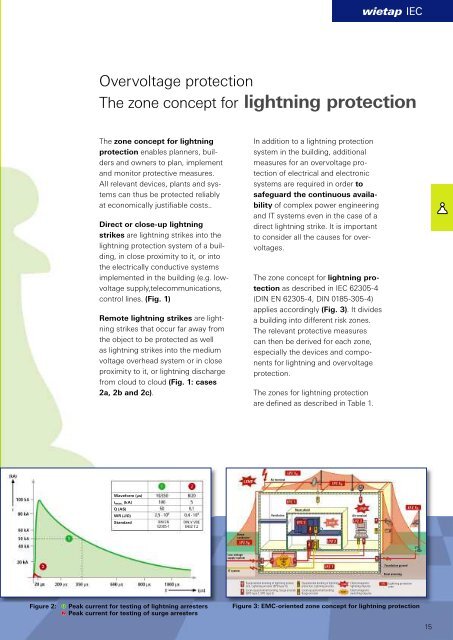
Overvoltage protection<br />
The zone concept for lightning protection<br />
The zone concept for lightning<br />
protection enables planners, builders<br />
and owners to plan, implement<br />
and monitor protective measures.<br />
All relevant devices, plants and systems<br />
can thus be protected reliably<br />
at economically justifi able costs..<br />
Direct or close-up lightning<br />
strikes are lightning strikes into the<br />
lightning protection system of a building,<br />
in close proximity to it, or into<br />
the electrically conductive systems<br />
implemented in the building (e.g. lowvoltage<br />
supply,telecommunications,<br />
control lines. (Fig. 1)<br />
Remote lightning strikes are lightning<br />
strikes that occur far away from<br />
the object to be protected as well<br />
as lightning strikes into the medium<br />
voltage overhead system or in close<br />
proximity to it, or lightning discharge<br />
from cloud to cloud (Fig. 1: cases<br />
2a, 2b and 2c).<br />
In addition to a lightning protection<br />
system in the building, additional<br />
measures for an overvoltage protection<br />
of electrical and electronic<br />
systems are required in order to<br />
safeguard the continuous availability<br />
of complex power engineering<br />
and IT systems even in the case of a<br />
direct lightning strike. It is important<br />
to consider all the causes for overvoltages.<br />
The zone concept for lightning protection<br />
as described in IEC 62305-4<br />
(DIN EN 62305-4, DIN 0185-305-4)<br />
applies accordingly (Fig. 3). It divides<br />
a building into different risk zones.<br />
The relevant protective measures<br />
can then be derived for each zone,<br />
especially the devices and components<br />
for lightning and overvoltage<br />
protection.<br />
The zones for lightning protection<br />
are defi ned as described in Table 1.<br />
Air terminal<br />
Waveform (µs)<br />
i max. (kA)<br />
Q (AS)<br />
WR (J/Ω)<br />
Standard<br />
Ventilation<br />
Room shield<br />
Air terminal<br />
Down<br />
conductor<br />
Low-voltage<br />
supply system<br />
IT system<br />
Foundation ground<br />
Steel armoring<br />
Equipotential bonding of lightning protection,<br />
Lightning arrester (SPD type 1))<br />
Local equipotential bonding, Surge arrester<br />
(SPD type 2, SPD type 3)<br />
Equipotential bonding of lightning<br />
protection, Lightning arrester<br />
Local equipotential bonding<br />
Surge arrester<br />
Electromagnetic<br />
lightning impulse<br />
Electromagnetic<br />
switching impulse<br />
Lightning protection<br />
zone<br />
Figure 2:<br />
➀ Peak current for testing of lightning arresters<br />
➁ Peak current for testing of surge arresters<br />
Figure 3: EMC-oriented zone concept for lightning protection<br />
15