SERVICE BULLETIN
SERVICE BULLETIN
SERVICE BULLETIN

Create successful ePaper yourself
Turn your PDF publications into a flip-book with our unique Google optimized e-Paper software.
<strong>SERVICE</strong> <strong>BULLETIN</strong><br />
M-1100 July 10, 2000<br />
®<br />
CAM BEARING REPAIR KITS<br />
General<br />
Two repair kits are now available to expedite rear cam<br />
bearing repair on 1999 and early 2000 model Twin Cam 88<br />
and Twin Cam 88B engines. One kit is for fuel injected<br />
vehicles, the other for carbureted. See Table 1 for part<br />
numbers and contents of each kit.<br />
Once a problem has been identified as the rear cam bearing,<br />
order the appropriate repair kit by electronically placing a<br />
“down” vehicle order (the VIN must be included). Then<br />
proceed with the instructions below.<br />
Removal<br />
NOTE<br />
After careful inspection, Harley-Davidson has determined<br />
that complete engine disassembly is unnecessary.<br />
All contamination is confined to the cam<br />
compartment and the return oiling system.<br />
1. Drain engine oil. Remove and discard engine oil filter.<br />
Regardless of model, see page 3-6 of the 2000 FLT<br />
Models Service Manual, Changing Engine Oil and Filter,<br />
steps 2-5.<br />
NOTE<br />
On DYNA models, the engine oil drain plug is on the left side<br />
of the oil pan. On SOFTAIL models, the drain plug for the oil<br />
tank is on right side of the lower frame crossmember.<br />
2. Strip the vehicle for service.<br />
• For FLT Models, see page 3-16 of the 2000 FLT<br />
Models Service Manual, Stripping Motorcycle for<br />
Service, steps 1-13.<br />
• For DYNA Models, see page 3-23 of the 2000<br />
DYNA Models Service Manual, Stripping<br />
Motorcycle for Service, steps 1-8.<br />
• For SOFTAIL Models, see page 3-23 of the 2000<br />
SOFTAIL Models Service Manual, Stripping<br />
Motorcycle for Service, steps 1-8.<br />
3. Remove the rocker covers, breather cover and baffle<br />
assemblies, push rod covers, rocker arm support plate<br />
assemblies, intake and exhaust push rods, lifter covers,<br />
anti-rotation pins, and hydraulic lifters. Tag parts for<br />
warranty.<br />
Regardless of model, see page 3-35 of the 2000 FLT<br />
Models Service Manual, Top End Overhaul,<br />
Disassembly, steps 1-13.<br />
4. Remove the cam cover, crank and primary cam sprockets,<br />
primary cam sprocket spacer, chain guide, cam<br />
support plate, and oil pump. Tag parts for warranty.<br />
Regardless of model, see page 3-47 of the 2000 FLT<br />
Models Service Manual, Bottom End Overhaul,<br />
Disassembly, steps 2-15.<br />
Table 1. Cam Bearing Repair Kits<br />
Description<br />
Part No.<br />
Fuel Injected Vehicles 24984-99<br />
Carbureted Vehicles 24985-99<br />
Each Repair Kit Contains the Following:<br />
Description Part Number Qty.<br />
EFI Camshafts<br />
or<br />
Carbureted Camshafts<br />
Front<br />
25296-99<br />
Rear<br />
25297-00<br />
1<br />
Each<br />
25534-99 25544-00<br />
Cam Needle Bearing 9198 2<br />
Cam Support Plate 25267-99B 1<br />
Cam Sprocket 25716-99 1<br />
Cam Sprocket Spacer Kit 25938-00 1<br />
Crank Sprocket 25609-99 1<br />
Primary Cam Chain 25610-99 1<br />
Secondary Cam Chain 25607-99 1<br />
Cam Gear Retention Kit 25533-99A 1<br />
Oil Pump Assembly 26035-99A 1<br />
Oil Pump O-Ring 11301 2<br />
Oil Pump O-Ring 11286 1<br />
Oil Pump/Push Rod<br />
Cover O-Ring<br />
11293 5<br />
Push Rod Cover O-Ring 11132 4<br />
Push Rod Cover O-Ring 11145 4<br />
Hydraulic Lifter 18538-99A 4<br />
Lifter Cover Gasket 18635-99 2<br />
Breather O-Ring 11270 2<br />
Umbrella Valve 26858-99 2<br />
Breather Baffle Gasket 17592-99 2<br />
Breather Cover Gasket 17591-99 2<br />
Rocker Cover Gasket 17386-99 2<br />
Cam Cover Gasket 25244-99 1<br />
FLT Oil Pan Gasket 26077-99 1<br />
DYNA Oil Pan Gasket 26072-99 1<br />
Parts Sold Separately<br />
M-1100 1 of 4
d0240b3x<br />
7<br />
9<br />
5<br />
4<br />
2<br />
Oil<br />
Drain Plug<br />
LEFT<br />
SIDE<br />
Cleaning and Inspection<br />
1. Thoroughly clean baffle assembly.<br />
2. Thoroughly clean oil pan and flush oil feed and return<br />
passages. Verify cleanliness.<br />
3. Flush oil feed and return passages at front of transmission<br />
housing. Verify cleanliness.<br />
1<br />
8<br />
NOTE<br />
RIGHT<br />
SIDE<br />
3<br />
On Softail models, drain oil tank, remove and flush oil feed<br />
and return lines, and then flush tank.<br />
Transmission<br />
Drain Plug<br />
6<br />
10<br />
DYNA OIL PAN<br />
Ten Screws<br />
4. Thoroughly clean cam compartment.<br />
5. Flush all oil feed and return fittings and hoses from<br />
engine to transmission housing.<br />
7<br />
5<br />
RIGHT<br />
SIDE<br />
f1677x3x<br />
11<br />
1<br />
4<br />
9<br />
Transmission<br />
Drain Plug<br />
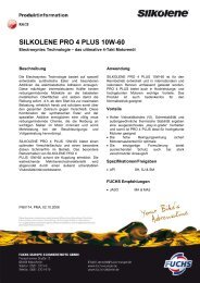
Figure 1. Oil Pan Torque Sequence<br />
5. Remove the cam needle bearings. Tag parts for<br />
warranty.<br />
Regardless of model, see page 3-88 of the 2000 FLT<br />
Models Service Manual, Subassembly Service and<br />
Repair, Cam Needle Bearings, Removal.<br />
6. On FLT and DYNA models, remove the oil pan as<br />
follows:<br />
NOTE<br />
Oil<br />
Drain Plug<br />
On FLT models, remove rear wheel before attempting to<br />
remove the oil pan. See page 2-9 of the 2000 FLT Models<br />
Service Manual, Rear Wheel, Removal.<br />
3<br />
a. Locate transmission drain plug on right side of the<br />
oil pan. See Figure 1. Remove the plug and drain<br />
the transmission lubricant into a suitable container.<br />
b. Following the pattern shown in Figure 1, alternately<br />
loosen and then remove the allen head socket<br />
screws to release the oil pan from the transmission<br />
housing.<br />
c. Remove gasket and baffle assembly from oil pan.<br />
Discard gasket.<br />
10<br />
FLT OIL PAN<br />
Twelve Screws<br />
2<br />
6<br />
12<br />
LEFT<br />
SIDE<br />
8<br />
Installation<br />
1. Obtain the appropriate Cam Bearing Repair Kit, either<br />
fuel injected or carbureted.<br />
2. Install new cam needle bearings. Regardless of model,<br />
see page 3-89 of the 2000 FLT Models Service Manual,<br />
Subassembly Service and Repair, Cam Needle Bearings,<br />
Installation.<br />
3. Using the new parts, install the oil pump, cam support<br />
plate, chain guide, primary cam sprocket spacer, crank<br />
and primary cam sprockets, and cam cover.<br />
Regardless of model, see page 3-49 of the 2000 FLT<br />
Models Service Manual, Bottom End Overhaul,<br />
Assembly, steps 5-23.<br />
NOTE<br />
Primary cam sprocket spacers in the Cam Bearing Repair<br />
Kit are color coded for ease of identification. See Table 2<br />
below.<br />
Table 2. Primary Cam Sprocket Spacers<br />
Spacer Size<br />
Color<br />
0.287 Red<br />
0.297 Black<br />
0.307 Blue<br />
0.317 Green<br />
0.327 Gold<br />
4. Using the new parts, install the hydraulic lifters, antirotation<br />
pins, lifter covers, intake and exhaust push rods,<br />
rocker arm support plate assemblies, push rod covers,<br />
breather cover and baffle assemblies, and rocker<br />
covers.<br />
Regardless of model, see page 3-43 of the 2000 FLT<br />
Models Service Manual, Top End Overhaul, Assembly,<br />
steps 25-39.<br />
5. On FLT and DYNA models, install the oil pan as follows:<br />
2 of 4 M-1100
a. Coat gasket surface of oil pan with a thin coat of<br />
HYLOMAR® gasket sealer.<br />
b. Place gasket on oil pan and allow sealer to dry until<br />
tacky.<br />
c. Position oil pan under transmission housing and<br />
start the allen head socket screws. Tighten each<br />
screw about two turns after initial thread<br />
engagement.<br />
d. Inspect the oil pan gasket to verify that it is properly<br />
positioned.<br />
e. Alternately tighten the oil pan screws to 7-9 ft-lbs<br />
(9-12 Nm) following the pattern shown in Figure 1.<br />
NOTE<br />
On FLT models, install rear wheel. See page 2-12 of the<br />
2000 FLT Models Service Manual, Rear Wheel, Installation.<br />
f. Remove any foreign material from magnet of<br />
transmission lubricant drain plug. Also check the O-<br />
ring for tears, cuts or general deterioration. Replace<br />
as necessary.<br />
g. Install the transmission lubricant drain plug in right<br />
side of the oil pan. Tighten drain plug to 14-21 ft-lbs<br />
(19-28 Nm).<br />
h. Remove the transmission filler plug from the clutch<br />
release cover on the right side of the transmission<br />
case. Check the O-ring for tears, cuts or general<br />
deterioration. Replace as necessary.<br />
11WARNING 1WARNING<br />
When adding transmission lubricant, do not allow dirt,<br />
debris or other contaminants to enter the transmission<br />
case. Exercise caution so that lubricant does not contact<br />
rear wheel, tire and brake components. Such contact<br />
can adversely affect traction and may lead to loss of<br />
vehicle control, which could result in death or serious<br />
injury.<br />
i. Fill the transmission with 20-24 oz. (590-710 ml) of<br />
transmission lubricant or until the lubricant level on<br />
the dipstick of the filler plug is at the F(ULL) mark<br />
with the motorcycle in a level, upright position and<br />
the filler plug resting on the threads. Use only<br />
Harley-Davidson TRANSMISSION LUBRICANT,<br />
Part No. 98853-96 (quart) or Part No. 98852-96<br />
(gallon).<br />
j. Install the transmission filler plug/dipstick in the<br />
clutch release cover. Tighten the plug to 25-75 inlbs<br />
(2.8-8.5 Nm).<br />
6. Reassemble the vehicle after service.<br />
• For FLT Models, see page 3-17 of the 2000 FLT<br />
Models Service Manual, Assembling Motorcycle<br />
After Stripping, steps 8-19.<br />
• For DYNA Models, see page 3-24 of the 2000<br />
DYNA Models Service Manual, Assembling<br />
Motorcycle After Stripping, steps 6-12.<br />
• For SOFTAIL Models, see page 3-24 of the 2000<br />
SOFTAIL Models Service Manual, Assembling<br />
Motorcycle After Stripping, steps 5-13.<br />
7. Install a new engine oil filter. Add engine oil.<br />
Regardless of model, see page 3-6 of the 2000 FLT<br />
Models Service Manual, Changing Engine Oil and Filter,<br />
steps 6-10. When performing step 9, be aware that<br />
different models have different oil capacities, as shown<br />
in Table 3 below. Add only the amount shown under the<br />
wet capacity column.<br />
Table 3. Wet/Dry Oil Capacities (Quarts)<br />
Model Wet Dry<br />
FLT 3.5 4.0<br />
DYNA 2.5 3.0<br />
SOFTAIL 3.0 3.5<br />
NOTE<br />
To perform the engine oil level COLD CHECK on SOFTAIL<br />
models, verify that oil level registers on the dipstick with the<br />
vehicle upright and level. If it does not, look into the oil tank<br />
to see if the level is at or near the filler neck weld. If<br />
necessary, add only enough oil to bring the level to the filler<br />
neck weld.<br />
8. Perform engine oil HOT CHECK. Regardless of model,<br />
see page 3-6 of the 2000 FLT Models Service Manual,<br />
Changing Engine Oil and Filter, steps 11-12.<br />
9. See CREDIT PROCEDURE below.<br />
Credit Procedure<br />
In the event of a cam bearing failure, follow the instructions<br />
on page 1 to remove the cam support plate and oil pump.<br />
Replace parts and hardware with contents of one of two kits.<br />
NOTE<br />
If the vehicle is no longer under warranty, follow the parts<br />
ordering and repair process outlined in this bulletin. Then,<br />
after the repair is complete, submit a goodwill policy<br />
adjustment form by FAX.<br />
For each vehicle serviced, complete a separate Warranty<br />
Claim Form referencing Service Bulletin M-1100 in the<br />
“Description of Repair” section. In addition, the claim must<br />
contain the VIN (Vehicle Identification Number) of the vehicle<br />
on which the service was performed. Fill in the rest of the<br />
claim as follows:<br />
M-1100 3 of 4
CLAIM TYPE<br />
MC, GDW*<br />
QTY. EVENT 1 0<br />
EVENT 1, PROBLEM PART NO. 8990<br />
PART DESCRIPTION Rear Cam Bearing<br />
EVENT 1<br />
(QUANTITY - ADDITIONAL PARTS)<br />
1 - 24984-99 Fuel Injected Kit<br />
1 - 24985-99 Carbureted Kit<br />
1 - Oil Filter Part Number<br />
Either 63798-99 (Chrome) or<br />
63731-99 (Black)<br />
Appropriate quantity (in whole<br />
numbers) for TRANSMISSION<br />
LUBRICANT and ENGINE OIL<br />
PRIMARY LABOR CODE 3340<br />
TIME<br />
FLT<br />
DYNA<br />
SOFTAIL<br />
4.5 hrs.<br />
4.0 hrs.<br />
3.5 hrs.<br />
CUSTOMER CONCERN 4102<br />
CONDITION CODE 2208<br />
*Use “MC” if vehicle is still under factory warranty. Use<br />
“GDW” if vehicle is out of warranty, and you have obtained<br />
repair authorization from the factory. Be sure to include the<br />
authorization number obtained from the factory, if<br />
applicable.<br />
Upon receipt of the properly completed claim, you will<br />
receive the labor credit shown above for performing the<br />
required service, and you also will receive the appropriate<br />
credit for parts.<br />
ROUTING<br />
<strong>SERVICE</strong><br />
MANAGER<br />
SALES<br />
MANAGER<br />
PARTS<br />
MANAGER<br />
LEAD<br />
TECHNICIAN<br />
TECHNICIAN<br />
NO. 1<br />
TECHNICIAN<br />
NO. 2<br />
TECHNICIAN<br />
NO. 3<br />
TECHNICIAN<br />
NO. 4<br />
RETURN<br />
THIS TO:<br />
INITIAL HERE<br />
2000 Harley-Davidson ® Motor Company<br />
4 of 4 M-1100