Service Bulletin Harley Davidson New Rear CAM ... - HawaiiAirbrush
Service Bulletin Harley Davidson New Rear CAM ... - HawaiiAirbrush
Service Bulletin Harley Davidson New Rear CAM ... - HawaiiAirbrush

Create successful ePaper yourself
Turn your PDF publications into a flip-book with our unique Google optimized e-Paper software.
SERVICE BULLETINM-1097 December 21, 1999®NEW REAR <strong>CAM</strong> ROLLER BEARING ASSEMBLYGeneralEffective December 14, 1999, a new rear cam roller bearingassembly has been installed in both Twin Cam 88 and TwinCam 88B engines. To service these assemblies, or toreplace the earlier style ball bearing using the new parts,proceed with the instructions below.NOTEThe new rear cam roller bearing assembly will retrofit allsplined rear cams.RemovalCAUTIONCam bearings may be a loose fit in the cam supportplate. To avoid possible damage, be aware that camshaftand bearing assemblies may drop out at start of pressprocedure.1. Press out camshafts and bearings following existingservice procedures. Regardless of model, see page 3-83 of the 2000 FLT Models <strong>Service</strong> Manual, <strong>CAM</strong>-SHAFTS/<strong>CAM</strong>SHAFT BEARINGS, REMOVAL, steps 1-8.NOTESome bearing retainer plates may have circular marks if thebearing has turned. Disregard these marks if observed asthe retainer plate may continue to be used.b. Obtain two 3/8-16 inch bolts 3-1/2 inches long (withflat washers). Install flat washers on bolts. Obtainbridge, forcing screw and hardened plug fromMAINSHAFT BEARING INNER RACE PULLER/INSTALLER (HD-34902B).c. Slide one bolt into channel on each side of bridge,so that flat washer is between bridge and bolt head.Thread bolts into wedge attachment an equal numberof turns.d. Sparingly apply graphite lubricant to threads offorcing screw to prolong service life and ensuresmooth operation. Start forcing screw into centerhole of bridge.CAUTIONFailure to use hardened plug may result in damage toforcing screw and/or camshaft.DescriptionPartNumberQty.Roller Bearing 8984 1Bearing Inner Race 8985 1Thrust Washer 8986 1O-Ring 11350 1Parts Not Sold Separately2. If the new style roller bearing is present, slide bearingfrom end of rear camshaft. Since bearing is a loose fiton cam, no pressing tools are required.NOTEWherever the earlier style ball bearings are used, usepressing tools following existing service procedures.Regardless of model, see page 3-84 of the 2000 FLT Models<strong>Service</strong> Manual, <strong>CAM</strong>SHAFTS/<strong>CAM</strong>SHAFT BEARINGS,REMOVAL, step 9.O-RingThrust Washer3. If reusing a rear camshaft that has the new style rollerbearing installed, remove the bearing inner race andthrust washer as follows:a. Position WEDGE ATTACHMENT (HD-95637-46A)on inboard side of thrust washer and turn hex nutsan equal number of turns to draw halves of wedgetogether.Roller BearingBearing Inner Racef1805x3xFigure 1. <strong>Rear</strong> Cam Roller Bearing Kit (P/N 8983)M-1097 1 of 4
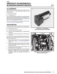
Roller Bearing<strong>Rear</strong> CamBall BearingFront Camg. Remove flange bolt, flat washer, sprocket andspacer.3. Install new cam bearings in cam support plate followingexisting service procedures. Regardless of model, seepage 3-85 of the 2000 FLT Models <strong>Service</strong> Manual,<strong>CAM</strong>SHAFTS/<strong>CAM</strong>SHAFT BEARINGS, INSTALLA-TION, steps 1-5.NOTEf1804x3xBe aware that the front and rear cam bearings are no longerinterchangeable. The rear bearing is now the roller type,while the front remains the ball bearing kind. See Figure 3.Figure 3. Cam Bearings2. Install O-ring, thrust washer and bearing inner race ontorear camshaft as follows:a. To properly locate thrust washer, first install O-ringin grinding relief groove. Groove is on the splinedend between the machined area and the secondarycam sprocket. Exercise caution to avoid stretchingor breaking the O-ring. Since the O-ring is not soldseparately, damage will require purchase of a newroller bearing kit.CAUTIONThe thrust washer will be offset to one side if the O-ringis not installed in the grinding relief groove. Damage tothe bearing cage can occur if the thrust washer is notproperly centered.b. Slide thrust washer down rear camshaft until centeredover O-ring in grinding relief groove.c. Slide bearing inner race down rear camshaft untilcontact is made with shoulder of machined area.d. Install primary cam sprocket spacer and sprocketon camshaft and secure using thicker flat washerand long flange bolt.NOTENOTEBearings may be a press to loose fit. If deemed necessary,clean bearing OD and apply Loctite Low StrengthThreadlocker 242 (Blue) before installation, but exercisecaution to avoid getting compound on rollers or bearing ID.4. Start camshafts into cam bearings following existingservice procedures. Regardless of model, see page 3-86 of the 2000 FLT Models <strong>Service</strong> Manual, <strong>CAM</strong>-SHAFTS/<strong>CAM</strong>SHAFT BEARINGS, INSTALLATION,steps 6-10.NOTEBe sure not to mix camshafts during the press procedure.The rear camshaft, which can be identified by the splinedshaft, must go into the roller bearing at the rear of the camsupport plate.5. Place cup of camshaft driver over end of front camshaftonly.CAUTIONVerify that splined end of rear camshaft has beenstarted into support block. Damage to the camshaft and/or support block can occur if end of camshaft catchestop of block during the press procedure.If not enough of the splined shaft is exposed to install thesprocket, leave out the spacer and proceed to step 2(e).Once the bearing inner race has been started onto themachined area, remove the flange bolt, washer andsprocket, and then reassemble using the spacer. Repeatstep 2(e) to fully install bearing inner race.f1809x3x<strong>Rear</strong> Cam BoreEnlargede. Wrap a shop rag around camshaft to get a firm gripand also to protect hand from sharp edges ofsprocket. Using a 9/16 inch box wrench, turn flangebolt in a clockwise direction. Bearing inner race isfully installed when it makes firm contact with thethrust washer. See B of Figure 2.f. Verify that the thrust washer is locked in place andcannot be rotated. If necessary, install shaft in viseusing brass jaw inserts, and further tighten flangebolt until the desired result is achieved.Support BlockFigure 4. Enlarge <strong>Rear</strong> Cam Bore Using 7/8 Inch Drill BitM-1097 3 of 4
NOTETo reduce the likelihood of such contact occuring, use 7/8inch drill bit to enlarge rear cam bore in support block. Forbest results, radius top inside edge of bore after drilling. SeeFigure 4.CAUTIONBe sure that the tensioner shoe is clear of the secondarycam chain during the press procedure. Contact canresult in damage that requires replacement of the tensionerassembly.6. Center end of front camshaft under ram and slowlyapply pressure to driver just to start front camshaft intobearing ID.CAUTIONIf rear camshaft is not properly aligned, edge of installedinner race can catch on bearing rollers. Bearing damagecan result if contact occurs during the press procedure.7. Slowly apply pressure to driver on front camshaft, whilewiggling rear camshaft as necessary to guide inner racebetween bearing rollers.8. When inner race on rear cam is started into rollerbearing, apply pressure to driver until front camshaft isfully seated. If necessary, keep finger pressure at top ofrear camshaft to ensure that assembly remains squareand inner race moves to installed position in roller bearing.9. Complete installation of cams. See page 3-86 of the2000 FLT Models <strong>Service</strong> Manual, <strong>CAM</strong>SHAFTS/<strong>CAM</strong>SHAFT BEARINGS, INSTALLATION, steps 14-15.IMPORTANT NOTEWhen installing crank and primary cam sprockets, pushon rear camshaft to remove end play and checkalignment of sprocket faces as described in the 2000FLT Models <strong>Service</strong> Manual, and shown in the upperframe of Figure 5. If alignment exceeds 0.010 inch,substitute existing spacer with one of those shown inTable 1. These spacers represent a new set and are to beused with the new rear cam roller bearing assemblyonly. Do not attempt to use earlier design spacers asthey will not work.Spacer SizeH-D Part Number0.287 25722-000.297 25723-000.307 25721-000.317 25719-000.327 25717-00Figure 5. Use <strong>New</strong> Spacers to Align Crank andPrimary Cam Sprocket Facesf1647x3xTable 1. <strong>New</strong> Primary Cam Sprocket SpacersWhen ordering service parts for replacement, please refer toTable 2 below.Table 2. Fitment InformationPart No. Description Fitment25267-99B Cam Support Plate w/Bearings & Oil Control Kit24598-99B Cam Support Plate w/Cams, CARB24606-99B Cam Support Plate w/Cams, EFI99-00 TC 88-88B99-00 TC 88-88B CARB99-00 TC 88-88B EFINOTE: All kits come with the new rear cam rollerbearing assembly, but do not include the new spacers.ROUTINGSERVICEMANAGERSALESMANAGERPARTSMANAGERLEADTECHNICIANTECHNICIANNO. 1TECHNICIANNO. 2TECHNICIANNO. 3TECHNICIANNO. 4RETURNTHIS TO:INITIAL HERE1999 <strong>Harley</strong>-<strong>Davidson</strong> ® Motor Company4 of 4 M-1097