In-cylinder Ion Sensing Opportunities
In-cylinder Ion Sensing Opportunities
In-cylinder Ion Sensing Opportunities

You also want an ePaper? Increase the reach of your titles
YUMPU automatically turns print PDFs into web optimized ePapers that Google loves.
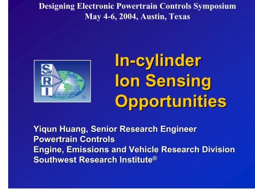
Designing Electronic Powertrain Controls SymposiumMay 4-6, 2004, Austin, Texas<strong>In</strong>-<strong>cylinder</strong><strong>Ion</strong> <strong>Sensing</strong><strong>Opportunities</strong>Yiqun Huang, Senior Research EngineerPowertrain ControlsEngine, Emissions and Vehicle Research DivisionSouthwest Research <strong>In</strong>stitute ®
Why Do We Need <strong>Ion</strong> <strong>Sensing</strong> ?• For SI engine, to increase performance and lower fuel consumption,n,operating close to MBT timing is desirable– But it is limited by knocking– Accurate knock detection over all engine operating conditionsis required• To meet stringent emissions standard, misfire detection is requiredredfor all engine speeds for OBD-II• Deficiencies of current methods– Accelerometer sensor for knock detection loses accuracy athigh engine speed due to vibration noise and could not detectearly knocking– Traditional speed variation method for misfire detectionbecomes difficult for multiple <strong>cylinder</strong> engines (V6, V8) and athigh engine speed• Other sensors to accomplish these tasks have cost and technicallimitations• All these problems can be solved by in-<strong>cylinder</strong> ion sensing
What Is <strong>Ion</strong> <strong>Sensing</strong>?• <strong>Ion</strong> <strong>Sensing</strong>-Measuring ionization currentgenerated from combustion through sparkplug electrodes• Extra measurement provided from the existingignition system, - no added in-<strong>cylinder</strong>instrumentation• Electronics added to existing hardware• Directly reflects in-<strong>cylinder</strong> combustionprocess• Provides accurate misfire and knock detection• Potentials for advanced engine controlapplication
Background of <strong>Ion</strong> <strong>Sensing</strong>• Being studied for automotive byresearchers before 1980 for A/F ratio,<strong>cylinder</strong> pressure estimation• <strong>In</strong>stalled in-<strong>cylinder</strong> or outside <strong>cylinder</strong>close to the exhaust port• Used on SAAB Direct-IgnitionTM systemsince 1987 and later on SAAB Trionicsystem (by Mecel)• Originally for <strong>cylinder</strong> synchronizationand pre-ignition detection• Knock and misfire detection wereintroduced in 1992 on SAAB (by Mecel)• <strong>In</strong>-<strong>cylinder</strong> detection is used - each<strong>cylinder</strong>
Mechanism of <strong>In</strong>-<strong>cylinder</strong> <strong>Ion</strong> <strong>Sensing</strong>• <strong>Ion</strong>s produced by chemical and thermalionization:CH + O → CHO + + e -CHO + +H 2 O → H 3 O + + COM+ E ion ←→ M + + e -• Measuring circuitry integrated with the ignitionelectronics system• Controlling of spark event is unaffected• No mechanical modification of engine needed
Mechanism of <strong>In</strong>-<strong>cylinder</strong> <strong>Ion</strong> <strong>Sensing</strong>From EuropeanAutomotive Des(Delphi AutomotSystem)• <strong>Ion</strong> current sensing is based on applying a low-voltageDC bias to the spark plug electrodes• The spark current used to create this bias voltage isaccumulated by a capacitor inside the ignition coil,eliminating the need for any additional voltage source
Mechanism of <strong>In</strong>-<strong>cylinder</strong> <strong>Ion</strong> <strong>Sensing</strong>From EuropeanAutomotive Des(Delphi AutomotSystem)• The measured current after the spark event reflects thecombustion process• Other related parameters are extracted through signalprocessing
Mechanism of <strong>In</strong>-<strong>cylinder</strong> <strong>Ion</strong> <strong>Sensing</strong>From EuropeanAutomotive Des(Delphi AutomotSystem)• Knock causes high frequency modulation of ion currentsignal• The modulated signal is obtained by passing through aband pass filter
Example Hardware of<strong>In</strong>-<strong>cylinder</strong> <strong>Ion</strong> <strong>Sensing</strong>Mitsubishi Electric<strong>Ion</strong>ization DetectionModuleSAAB Trionic SystemSAAB <strong>Ion</strong> Detection and Ignition coilDelphi <strong>Ion</strong>izationDetection System
Example Hardware of<strong>In</strong>-<strong>cylinder</strong> <strong>Ion</strong> <strong>Sensing</strong><strong>In</strong>fineon Technologies AG:Smart IGBT block with possiblefunctionsSmart IGBT on Chip-on-ChipFrom SAE 2004-01-0518
Current EffortsEarly knock detection- traditional accelerometer type knocksensor could not detect early,inaudible knockCombustion condition detection - leanlimit control- cold start application
Knock Detection<strong>Ion</strong> & <strong>cylinder</strong>pressure signalsKnock sensorKnock signalfrom ion sensing& pressuresensorSAE 2003-0101-3149• Heavy, audible knocking• Knock sensor, ionsensing and pressuresensor pick up theknocking signal• Light knocking, inaudible• Knock sensor at the noiselevel and misses knock• <strong>Ion</strong> sensing and pressuresensor pick up theknocking signal
Knock Detection at High Speed<strong>Ion</strong> signalKnock sensorKnock signalfrom ion sensing• Audible knocking at high speed• Knock sensor loses thecapability to detect knock due tohigh noise from vibration• <strong>Ion</strong> sensing picks up theknocking signalSAE 2003-0101-3149• No knocking at high speed• Knock sensor at the noiselevel and may indicateknock• <strong>Ion</strong> sensing shows noknocking
Further Improvement Needed forQuantitative ApplicationHardware Development:– High speed sampling for cycleresolved ion signal– ECU throughput improvement forcycle resolved data processing– Current coil design tends to low-pass filter ion signal• Coil redesign required
Further Improvement Needed forQuantitative Application - (Cont.)<strong>Ion</strong> signals are also affected by:– Engine operating conditions– Fuel additives– Spark plug conditionMust quantify these effects byadditional fundamental research
Fundamental Research• Understandingmechanism andaffecting factors• DesignimprovementKnife EdgeMirror 2Lens 3CameraLens 2Lens 1SwRI Combustion Bombs andHigh Speed Combustion ImagingMirror 1
Fundamental Research - (Cont.)1.4Ignition Command, <strong>Ion</strong>ization, volts1.210.80.60.40.25.55 ms6.57 ms28.60 msignition commandion signal, volts<strong>cylinder</strong> pressure15001000500Cylinder pressure, kPa000 20 40 60 80 100Time, ms- <strong>Ion</strong> signal timing relations
Characteristics of <strong>Ion</strong> Signal0.40.350.3Location of the peak ionizationsignal from spark commandSignal reflectingthe sparkPeak of the ionization signalThe characteristicsof ion signal:–Peak–Peak location–Area<strong>Ion</strong> Signal, volts0.250.20.150.10.050Ignition dwell<strong>In</strong>itial <strong>Ion</strong>izationassociated withthe flame front1.0950 10 20 30 40TIME (ms)φ =Area covered by the ionization signal<strong>Ion</strong>ization under controlledenvironment
Location & Magnitude of <strong>Ion</strong>ization Peaks and<strong>In</strong>tegration of <strong>Ion</strong>ization - Combustion Bomb Result<strong>In</strong>tegration of <strong>Ion</strong>ization, volt. ms400350300250200150100500<strong>In</strong>tegration - Test 1<strong>In</strong>tegration - Test 2<strong>In</strong>tegration - Test 30.6 0.7 0.8 0.9 1.0 1.1 1.2 1.3 1.4 1.5phiLocation of the Peak <strong>Ion</strong>ization from spark, ms4540353025201510Location of Peak <strong>Ion</strong>ization (ms) - Test 1Location of Peak <strong>Ion</strong>ization (ms) - Test 2Location of Peak <strong>Ion</strong>ization (ms) - Test 30.6 0.7 0.8 0.9 1.0 1.1 1.2 1.3 1.4 1.5phiPeak Magnitude, volts0.450.400.350.300.250.200.150.100.050.00Peak <strong>Ion</strong>ization - Test 1Peak <strong>Ion</strong>ization - Test 2Peak <strong>Ion</strong>ization - Test 30.6 0.7 0.8 0.9 1.0 1.1 1.2 1.3 1.4 1.5phi• The timing of the peak ion signal isminimum at slightly rich• The area covered by ion signal peaksat slightly rich, but decays faster onthe lean side• Peak magnitude of ion signal showssimilar trends as area covered by theion signal
Neural Network Prediction- Combustion Bomb ResultsLocation of the Peak <strong>Ion</strong>ization from spark, ms4540353025201510Location of Peak <strong>Ion</strong>ization (ms) - Test 1Location of Peak <strong>Ion</strong>ization (ms) - Test 2Location of Peak <strong>Ion</strong>ization (ms) - Test 30.6 0.7 0.8 0.9 1.0 1.1 1.24001.3 1.4 1.5phi<strong>In</strong>tegration of <strong>Ion</strong>ization, volt. ms35030025020015010050<strong>In</strong>tegration - Test 1<strong>In</strong>tegration - Test 2<strong>In</strong>tegration - Test 3Equivalence Ratio1.81.61.41.210.8PredictedMeasured00.450.6 0.7 0.8 0.9 1.0 1.1 1.2 1.3 1.4 1.50.40 phi0.350.6Peak Magnitude, volts0.300.250.200.150.100.050.00Peak <strong>Ion</strong>ization - Test 1Peak <strong>Ion</strong>ization - Test 2Peak <strong>Ion</strong>ization - Test 30.6 0.7 0.8 0.9 1.0 1.1 1.2 1.3 1.4 1.5phi0.40 20 40 60 80 100 120 140 160Test Points•The predicted results show lessaccuracy at Φ = ~1.0 to 1.1.
Speed Effect on <strong>Ion</strong> Signal<strong>Ion</strong>ization Signal, volt0.250.20.150.10.050-0.05Ignition CommandPeak magnitude increases withthe increase of RPMSignal Used600 rpm800 rpm1000 rpm1200 rpm0 2 4 6 8 10 12 14Time, msAt stoichiometric, no load•Peak - increases withspeed•Peak location - close tospark with speedincrease•Area - increases withspeed increaseSpeed Effect
Load Effect on <strong>Ion</strong> Signal<strong>Ion</strong>ization Signal, volt0.250.20.150.10.05200 Nm20 Nm100 Nm•Peak - increases withload•Peak location - close tospark with loadincrease0-0.050 2 4 6 8Time, msLoad Effect
Equivalence Ratio Effects atHigher Load and Different Speed0.251000 rpm0.252600 rpm•Peak magnitudeof ion signal -max at Φ = ~1.1<strong>Ion</strong> signal, volt0.20.150.10.051.2981.1671.0590.9870.878<strong>Ion</strong> Signal, volt0.20.150.10.051.2711.121.030.9380.885•Peak location -closest to sparkat max Φ<strong>Ion</strong> Signal, volt0.250.1500 0.001 0.002 0.003 0.004 0.005time, s0.20.11400 rpm0.8850.8790.9241.0981.185<strong>Ion</strong> Signal, volt00 0.001 0.002 0.003 0.004time, s3000 rpm0.250.20.150.11.261.1571.0250.8880.8550.050.0500 0.001 0.002 0.003 0.004 0.005time, s00 0.001 0.002 0.003 0.004time, s
<strong>Ion</strong> Signal in Time Domainand Crank Angle Domain0.250.25<strong>Ion</strong>ization, volts0.200.150.103000 rpm, phi 1.0252600 rpm, phi 1.0302200 rpm, phi 1.0151400 rpm, phi 1.0981000 rpm, phi 1.059<strong>Ion</strong>ization, volts0.200.150.103000 rpm, phi 1.0252600 rpm, phi 1.0302200 rpm, phi 1.0151400 rpm, phi 1.0981000 rpm, phi 1.0590.050.050.000 2 4 6Time, ms0.000 25 50 75Crank Angle Degree•Processing in crank angle domain isneeded for the area covered by ionization.
Location of Peak <strong>Ion</strong>ization Signal- Engine Test vs Combustion Bomb TestLocation of the Peak <strong>Ion</strong>ization from spark, ms4540353025201510Location of Peak <strong>Ion</strong>ization (ms) - Test 1Location of Peak <strong>Ion</strong>ization (ms) - Test 2Location of Peak <strong>Ion</strong>ization (ms) - Test 30.6 0.7 0.8 0.9 1.0 1.1 1.2 1.3 1.4 1.5phiLocation of peak ionization, ms from spark2.22.01.81.61.41.21.00.80.60.40.20.00.8 0.9 1.0 1.1 1.2 1.3 1.4Equivalence ratio3000 rpm2600 rpm2200 rpm1400 rpm1000 rpm• From bomb test -Peak location is closest tothe spark at Φ = ~ 1.05,symmetric• From engine test -Peak location is closestto the spark at max Φ
Potentials for Reducing Cold StartEquivalence ratio1.61.41.210.80.6and Warm-up Enrichmentphi: cyl. #1phi: engineEquivalence ratio could be closer to 1by closed loop control0.40 5 10 15 20 25 30TIME (Sec)Equivalence ratio duringstart and warm-up• Online calibration is needed forvariations in fuel properties andspark plug condition• Idle condition can be used as anonline calibration point• ion signal character parameterscan be normalized by the valuesat the calibration condition.AtinputinputPinput===AmeaAtPmeatmea• f (∆A)bas _ online• f (∆t)bas _ onlineP• f (∆P)bas _ online
Summary• The development of ion sensing technology isstill continuing• Successfully used in production vehicles forknock detection and misfire detection– demonstrated advantages over other methods• Early knock detection and control by ion sensingis very promising• <strong>Ion</strong> sensing has demonstrated high potential foradjusting ignition timing and air/fuel ratio onindividual <strong>cylinder</strong> basis
Summary - (Cont.)• Cold start is a very important area for ion sensingto apply for– AF ratio estimation: could be a neuralnetwork model– Could be useful as feedback for closed loopAir/Fuel ratio control during the engine warmup period when the oxygen sensor iswarming up.
Summary - (Cont.)• Engine operating conditions have strong effectson ionization detection,– including the location of peak ionization,peak magnitude and area covered byionization• Calibration issue must be resolved– idle condition can be used as an on-linecalibration point for the ionizationmeasurement after the oxygen sensorwarms up.• Measurement derived from the ion signals can behelpful for optimizing engine combustion
ContactYiqun HuangPowertrain ControlsEngine, Emissions and Vehicle Research DivisionSouthwest Research <strong>In</strong>stituteyhuang@swri.orgTel:210-522522-25642564