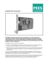
PEES ADN 411 - PEES COMPONENTS
PEES ADN 411 - PEES COMPONENTS
PEES ADN 411 - PEES COMPONENTS

Create successful ePaper yourself
Turn your PDF publications into a flip-book with our unique Google optimized e-Paper software.
<strong>PEES</strong><br />
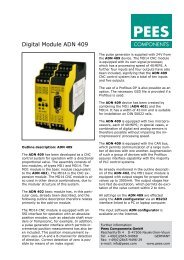
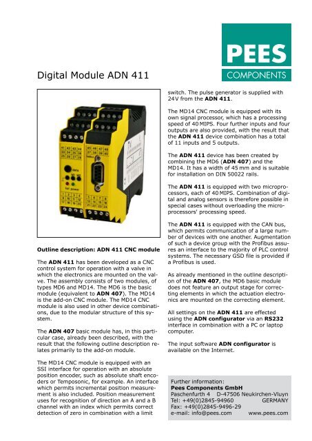
Digital Module <strong>ADN</strong> <strong>411</strong><br />
<strong>COMPONENTS</strong><br />
switch. The pulse generator is supplied with<br />
24V from the <strong>ADN</strong> <strong>411</strong>.<br />
The MD14 CNC module is equipped with its<br />
own signal processor, which has a processing<br />
speed of 40 MIPS. Four further inputs and four<br />
outputs are also provided, with the result that<br />
the <strong>ADN</strong> <strong>411</strong> device combination has a total<br />
of 11 inputs and 5 outputs.<br />
The <strong>ADN</strong> <strong>411</strong> device has been created by<br />
combining the MD6 (<strong>ADN</strong> 407) and the<br />
MD14. It has a width of 45 mm and is suitable<br />
for installation on DIN 50022 rails.<br />
The <strong>ADN</strong> <strong>411</strong> is equipped with two microprocessors,<br />
each of 40 MIPS. Combination of digital<br />
and analog sensors is therefore possible in<br />
special cases without overloading the microprocessors'<br />
processing speed.<br />
Outline description: <strong>ADN</strong> <strong>411</strong> CNC module<br />
The <strong>ADN</strong> <strong>411</strong> has been developed as a CNC<br />
control system for operation with a valve in<br />
which the electronics are mounted on the valve.<br />
The assembly consists of two modules, of<br />
types MD6 and MD14. The MD6 is the basic<br />
module (equivalent to <strong>ADN</strong> 407). The MD14<br />
is the add-on CNC module. The MD14 CNC<br />
module is also used in other device combinations,<br />
due to the modular structure of this system.<br />
The <strong>ADN</strong> 407 basic module has, in this particular<br />
case, already been described, with the<br />
result that the following outline description relates<br />
primarily to the add-on module.<br />
The MD14 CNC module is equipped with an<br />
SSI interface for operation with an absolute<br />
position encoder, such as absolute shaft encoders<br />
or Temposonic, for example. An interface<br />
which permits incremental position measurement<br />
is also included. Position measurement<br />
uses for recognition of direction an A and a B<br />
channel with an index which permits correct<br />
detection of zero in combination with a limit<br />
The <strong>ADN</strong> <strong>411</strong> is equipped with the CAN bus,<br />
which permits communication of a large number<br />
of devices with one another. Augmentation<br />
of such a device group with the Profibus assures<br />
an interface to the majority of PLC control<br />
systems. The necessary GSD file is provided if<br />
a Profibus is used.<br />
As already mentioned in the outline description<br />
of the <strong>ADN</strong> 407, the MD6 basic module<br />
does not feature an output stage for correcting<br />
elements in which the actuation electronics<br />
are mounted on the correcting element.<br />
All settings on the <strong>ADN</strong> <strong>411</strong> are effected<br />
using the <strong>ADN</strong> configurator via an RS232<br />
interface in combination with a PC or laptop<br />
computer.<br />
The input software <strong>ADN</strong> configurator is<br />
available on the Internet.<br />
Further information:<br />
Pees Components GmbH<br />
Paschenfurth 4 D-47506 Neukirchen-Vluyn<br />
Tel: +49(0)2845-94960<br />
GERMANY<br />
Fax: +49(0)2845-9496-29<br />
e-mail: info@pees.com www.pees.com
Digital Module <strong>ADN</strong> <strong>411</strong><br />
Technical data:<br />
Supply voltage<br />
Bias current (idling)<br />
Auxiliary voltage<br />
Output signal<br />
Inputs<br />
Outputs<br />
Measuring sockets<br />
Ambient temperature<br />
Microprocessors<br />
Program cycle time<br />
Controller setting range<br />
Function generator<br />
24V DC, nominal (22 to 28V) DC<br />
approx. 70mA<br />
22 to 28V DC for supply of the sensors<br />
sustained short-circuit-proof via a 0.5A resettable fuse<br />
±20mA or 12mA ±8mA<br />
11, opto-decoupled, of which 1 x Enable<br />
5 x 24V/100mA<br />
The output signal can be measured at +/–10V for maximum level<br />
on Measuring Sockets M1 and M2.<br />
–20 to +60°C<br />
2 x 16 bit signal processors, each with a processing speed of 40 MIPS<br />
9.7kHz for the entire computer program, approx. 0.1ms<br />
1 to 32000 for P, I, DT1<br />
Sinusoidal, triangular and square-wave generator, with offset and amplitude<br />
setting of ±10V; frequency range is 0.1 to 50Hz<br />
Sensor modules for MD1 ±10V, 12mA ±8mA, 4–20mA, 0–10V, 7.5V ±4V<br />
Fault signalization<br />
Wire breakage in modules 12mA ±8mA 4–20mA 7.5V ±4V in case of<br />
short-circuit in the sensor supply. Signalization via a 24V/100mA output,<br />
flashing red LED and display on the <strong>ADN</strong> configurator<br />
Parametering<br />
Parameters are entered on the <strong>ADN</strong> configurator.<br />
This input software is available via the Internet.<br />
Position encoder<br />
absolute, via SSI interface, or incremental, via pulse generator<br />
Field bus<br />
CAN bus for external and internal communication; Profibus DP (optional)<br />
for communication with PLC control system or external sensors<br />
An USB-to-RS232 adapter is required for use with laptops with a USB interface.<br />
<strong>ADN</strong><strong>411</strong> • Right of modification reserved