AN527 Servo Amplifier - PEES COMPONENTS
AN527 Servo Amplifier - PEES COMPONENTS
AN527 Servo Amplifier - PEES COMPONENTS

You also want an ePaper? Increase the reach of your titles
YUMPU automatically turns print PDFs into web optimized ePapers that Google loves.
<strong>PEES</strong><br />
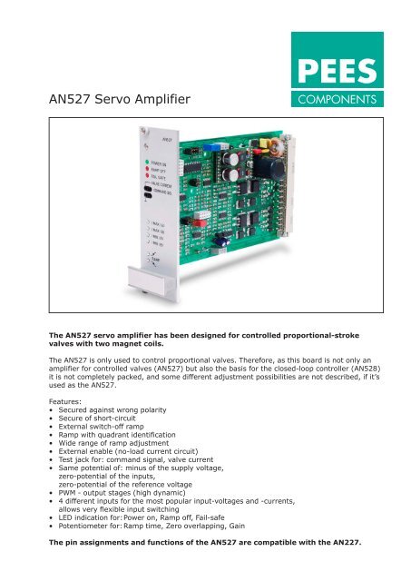
<strong>AN527</strong> <strong>Servo</strong> <strong>Amplifier</strong><br />
<strong>COMPONENTS</strong><br />
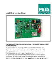
The <strong>AN527</strong> servo amplifier has been designed for controlled proportional-stroke<br />
valves with two magnet coils.<br />
The <strong>AN527</strong> is only used to control proportional valves. Therefore, as this board is not only an<br />
amplifier for controlled valves (<strong>AN527</strong>) but also the basis for the closed-loop controller (AN528)<br />
it is not completely packed, and some different adjustment possibilities are not described, if it’s<br />
used as the <strong>AN527</strong>.<br />
Features:<br />
• Secured against wrong polarity<br />
• Secure of short-circuit<br />
• External switch-off ramp<br />
• Ramp with quadrant identification<br />
• Wide range of ramp adjustment<br />
• External enable (no-load current circuit)<br />
• Test jack for: command signal, valve current<br />
• Same potential of: minus of the supply voltage,<br />
zero-potential of the inputs,<br />
zero-potential of the reference voltage<br />
• PWM - output stages (high dynamic)<br />
• 4 different inputs for the most popular input-voltages and -currents,<br />
allows very flexible input switching<br />
• LED indication for: Power on, Ramp off, Fail-safe<br />
• Potentiometer for: Ramp time, Zero overlapping, Gain<br />
The pin assignments and functions of the <strong>AN527</strong> are compatible with the AN227.
<strong>PEES</strong><br />
<strong>COMPONENTS</strong><br />
<strong>AN527</strong> <strong>Servo</strong> <strong>Amplifier</strong><br />
Power on<br />
DC<br />
DC<br />
a10<br />
a24<br />
a12<br />
a22<br />
c4<br />
a/c/16/18<br />
c12<br />
+10V<br />
-10V<br />
+15V<br />
-15V<br />
+24V<br />
0V<br />
Stabilised<br />
Reference<br />
Reference<br />
Supply<br />
±20mA<br />
±5V<br />
±10V<br />
User selectable<br />
10k Ω/V<br />
GND<br />
Stop<br />
Ramp off<br />
a26<br />
a28<br />
a30<br />
a32<br />
c26/28<br />
a2<br />
a4<br />
Up<br />
Down<br />
A<br />
Max<br />
A<br />
Min<br />
Dither<br />
J1 J2 J3<br />
B<br />
Max<br />
B<br />
Min<br />
TP2<br />
Current limit<br />
J6<br />
c8<br />
c10<br />
c6<br />
c2<br />
c22<br />
c24<br />
a8<br />
Magnet Coil A<br />
Magnet Coil B<br />
Current A/B<br />
1V / A<br />
Command signal<br />
Current A/B<br />
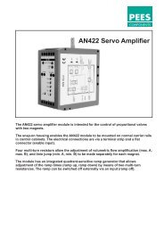
<strong>AN527</strong> servo amplifier for controlled proportionalstroke<br />
valves without position controller<br />
527BLO07 Rev.02 (06.10.1997)<br />
Technical Data:<br />
Dimensions<br />
(overall dim.)<br />
Connection<br />
Supply voltage<br />
Reference<br />
voltages<br />
Output current<br />
PWM frequency<br />
Short-circuit protection<br />
Signal inputs<br />
Dither<br />
Eurocard format (160x100)mm<br />
(40.5x128.7x189.7)mm (WxHxD), Front plate 3HUx8SU<br />
32 pin connector DIN 41612 D32<br />
24V DC (20–32V DC)<br />
±10V, 10mA, stabilised<br />
±15V, 25mA, unstabilised<br />
Imax = 2600 mA, 3 plug-selectable ranges: (0–800mA, 0–1600mA, 0–2600mA)<br />
Approx. 5.5 kHz<br />
for output stage and reference voltages<br />
1x ±20mA, 100Ω<br />
1x ±5V, 50kΩ<br />
1x ±10V, 100kΩ<br />
1x user selectable 10kΩ/V<br />
3 plug-selectable ranges (100 Hz, 140Hz, 280 Hz)<br />
Adjustable amplitude, approx. 0–10% of rated current.<br />
Ramp times Ramp up/down independently adjustable, 0.2–10sec 20%<br />
Ramp off<br />
Input voltage 24V, 10kΩ, Indication by LED 'Ramp off'<br />
Stop<br />
Normally closed circuit, Input voltage 24V, 10kΩ<br />
Indication by LED 'Fail safe'<br />
Measurement VALVE CURRENT: 1V = 1A, ±8%,<br />
sockets (ø 2 mm)<br />
COMMAND SIG: desired signal ±10V depends on the input voltage<br />
AN 527 V09 Rev01 • Subject to change without notice