AN430 servo amplifier/ PID controller - PEES COMPONENTS
AN430 servo amplifier/ PID controller - PEES COMPONENTS
AN430 servo amplifier/ PID controller - PEES COMPONENTS

You also want an ePaper? Increase the reach of your titles
YUMPU automatically turns print PDFs into web optimized ePapers that Google loves.
<strong>AN430</strong> <strong>servo</strong> <strong>amplifier</strong>/<br />
<strong>PID</strong> <strong>controller</strong><br />
<strong>PEES</strong><br />
<strong>COMPONENTS</strong><br />
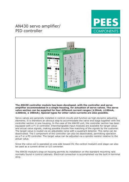
The <strong>AN430</strong> <strong>controller</strong> module has been developed, with the <strong>controller</strong> and <strong>servo</strong><br />
<strong>amplifier</strong> accommodated in a single housing, for actuation of <strong>servo</strong> valves. The <strong>servo</strong><br />
valve section can be supplied for four different current ranges (±20mA, ±100mA,<br />
±200mA, ± 300mA). Special types for other valve currents are also possible.<br />
Servo valves are generally installed in control circuits and function as high-dynamic adjusting<br />
elements. It is therefore an obvious step to accommodate the valve end stage together with the<br />
<strong>controller</strong> section in one housing. In the case of the <strong>AN430</strong> unit, the <strong>controller</strong> section has been<br />
equipped with a P I D <strong>controller</strong>. Interchangeable input modules are available for target value<br />
and actual value signals, making possible trouble free matching of the signals by the customer.<br />
The target value is routed via an adjustable ramp with a quadrant detector. This ramp can be<br />
deactivated. The I component of the <strong>controller</strong> can also be deactivated, permitting operation<br />
as a P or a PD <strong>controller</strong>. The target value can be adjusted via a spindle resistor relative to the<br />
actual value.<br />
Since the valve coil is operated on one side toward 0V, the control module’s end stage can also<br />
be used as a current driver or U/I converter.<br />
The <strong>AN430</strong> module’s snap on housing permits its installation on the standard mounting rails<br />
normally found in control cabinets. Electrical connection is accomplished via the built in terminal<br />
strip.
<strong>PEES</strong><br />
<strong>COMPONENTS</strong><br />
<strong>AN430</strong> <strong>servo</strong> <strong>amplifier</strong>/<br />
<strong>PID</strong> <strong>controller</strong><br />
Technical Data:<br />
Valve section<br />
Supply voltage<br />
24V DC (20...28V DC)<br />
Temperature range<br />
0...50°C<br />
Auxiliary voltages<br />
for supply of an external target value potentiometer:<br />
Terminal 4 = +10V (max. 5mA)<br />
Terminal 9 = GND<br />
Terminal 3 = -10V (max. 5mA)<br />
Output current depending on type ± 20mA<br />
±100mA<br />
±200mA<br />
±300mA<br />
Dither<br />
approx. 200 Hz works setting<br />
Amplitude selectable in a range from approx. 0 to 10% of the selected<br />
nominal current on the "Dither" potentiometer<br />
Instrument sockets Current Valve current (±10V)<br />
Command Target value ("setpoint") signal (±10V)<br />
M1<br />
Controller output<br />
Balance<br />
Zero-point calibration for valve/complete system<br />
Controller section<br />
Sensor modules<br />
Type EN272 V02<br />
(Target/Actual value)<br />
+/- 10V , 12mA +/- 8mA , 4-20mA , +/-20mA<br />
Switching inputs Ramp off, I Gain , CTRL on , Enable ,<br />
Nominal 24V ( 20-28 V)<br />
The four internal FET switches<br />
are set as follows in standby-position<br />
Enable FET switch = open Target value ON<br />
Ramp FET switch = open Ramp ON<br />
I gain FET switch = closed I <strong>controller</strong> OFF<br />
Velocity limit FET switch = closed Limiting ON<br />
AN 430 V01 Rev03 • Subject to change without notice