Infrared Detector Arrays
Infrared Detector Arrays
Infrared Detector Arrays

Create successful ePaper yourself
Turn your PDF publications into a flip-book with our unique Google optimized e-Paper software.
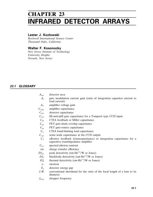
CHAPTER 23<br />
INFRARED DETECTOR ARRAYS<br />
Lester J . Kozlowski<br />
Rockwell International Science Center<br />
Thousand Oaks , California<br />
Walter F . Kosonocky<br />
New Jersey Institute of Technology<br />
Uni ersity Heights<br />
Newark , New Jersey<br />
2 3 . 1 GLOSSARY<br />
A d e t detector area<br />
A I gate modulation current gain (ratio of integration capacitor current to<br />
load current)<br />
A V amplifier voltage gain<br />
C a m p amplifier capacitance<br />
C d e t detector capacitance<br />
C F / S fill-and-spill gate capacitance for a Tompsett type CCD input<br />
C f b CTIA feedback or Miller capacitance<br />
C g d FET gate-drain overlap capacitance<br />
C g s FET gate-source capacitance<br />
C L CTIA band-limiting load capacitance<br />
C o u t sense node capacitance at the CCD output<br />
C T ef fective feedback (transcapacitance) or integration capacitance for a<br />
capacitive transimpedance amplifier<br />
C T spectral photon contrast<br />
cte charge transfer ef ficiency<br />
D * p k peak detectivity (cm-Hz 1 / 2 / W or Jones)<br />
D * b b blackbody detectivity (cm-Hz 1 / 2 / W or Jones)<br />
D * t h thermal detectivity (cm-Hz 1 / 2 / W or Jones)<br />
e- electron<br />
E g detector energy gap<br />
f / 4 conventional shorthand for the ratio of the focal length of a lens to its<br />
diameter<br />
f c h o p chopper frequency<br />
23 .1
23 .2 IMAGING DETECTORS<br />
f f r a m e display frame rate<br />
f k n e e frequency at which the 1 / f noise intersects the broadband noise<br />
f s spatial frequency (cycles/ radian)<br />
g m , L O A D gate transconductance of the load FET in the gate modulated input<br />
circuit<br />
g m gate transconductance of a Field Ef fect Transistor<br />
h Planck’s constant<br />
I D FET drain current<br />
I d e t detector current<br />
I p h o t o detector photocurrent<br />
k Boltzmann constant<br />
K a m p amplifier FET noise spectral density at 1 Hz<br />
K d e t detector noise spectral density at 1 Hz<br />
K F E T FET noise spectral density at 1 Hz<br />
L length-to-width ratio of a bar chart (always set to 7)<br />
MRT minimum resolvable temperature (K)<br />
MTF modulation transfer function for the optics , detector , readout , the<br />
integration process , or the composite sensor<br />
n detector junction ideality or dif fusion constant<br />
N amp , 1/f number of noise carriers for one integration time due to amplifier FET<br />
1 / f noise<br />
N amp , white number of noise carriers for one integration time due to amplifier FET<br />
white noise<br />
N c number of photo-generated carriers integrated for one integration time<br />
n d e t detector junction ideality or dif fusion constant<br />
NE T noise equivalent temperature dif ference (K)<br />
n F E T subthreshold FET ideality<br />
N F P A composite (total) FPA noise in carriers<br />
N kTC , channel CTIA broadband channel noise in carriers<br />
N load , white number of noise carriers for one integration time due to CTIA load FET<br />
white noise<br />
N o s display overscan ratio<br />
N P H O T O N shot noise of photon background in carriers<br />
NSD noise spectral density of a detector or field ef fect transistor ; the 1 / f noise<br />
is often specified by the NSD at a frequency of 1 Hz<br />
N s f source follower noise<br />
N s s serial scan ratio<br />
q electron charge in coulombs<br />
Q B photon flux density (photons/ cm 2 -s) incident on a focal plane array<br />
Q D charge detected in a focal plane array for one integration time
INFRARED DETECTOR ARRAYS 23 .3<br />
Q m a x maximum charge signal at saturation<br />
R d e t detector resistance<br />
R L O A D gate modulation load resistance<br />
R 0 detector resistance at zero-bias resistance<br />
R 0 A detector resistance-are product at zero-bias voltage<br />
R r detector resistance in reverse-bias resistance<br />
S / N signal-to-noise ratio<br />
SNR T target signal-to-noise ratio<br />
S V readout conversion factor describing the ratio of output voltage to<br />
detected signal carriers<br />
T operating temperature<br />
tce thermal coef ficient of expansion<br />
TCR thermal coef ficient of resistance for bolometer detectors<br />
T D time constant for correlated double sampling process normally set by<br />
Nyquist rate<br />
t i n t integration time<br />
U residual nonuniformity<br />
V b r detector reverse-bias breakdown voltage , sometimes defined as the<br />
voltage where R r R 0<br />
V D FET drain voltage<br />
V d e t detector bias voltage<br />
V D S FET grain-to-source voltage<br />
V G FET gate voltage<br />
n measured rms noise voltage<br />
A I gate modulation current gain nonuniformity<br />
f noise bandwidth (Hz)<br />
I p h o t o dif ferential photocurrent<br />
T scene temperature dif ference creating dif ferential photocurrent I p h o t o<br />
V S signal voltage for dif ferential photocurrent I p h o t o<br />
x horizontal detector subtense (mradian)<br />
y vertical detector subtense (mradian)<br />
detector quantum ef ficiency<br />
B L I P percentage of BLIP<br />
inj , DI injection ef ficiency of detector current into the source-modulated FET of<br />
the direct injection input circuit<br />
i n j injection ef ficiency of detector current<br />
n o i s e injection ef ficiency of DI circuit noise into integration capacitor<br />
p c quantum ef ficiency of photoconductive detector
23 .4 IMAGING DETECTORS<br />
p quantum ef ficiency of photovoltaic detector<br />
c detector cutof f wavelength (50 percent of peak response , m)<br />
d e t noise spectral density of total detector noise including photon noise<br />
input , ir noise spectral density of input-referred input circuit noise<br />
L O A D noise spectral density of input-referred load noise<br />
mux , ir noise spectral density of input-referred multiplexer noise<br />
V T rms threshold voltage nonuniformity across an FPA<br />
τ a m p amplifier time constant (s)<br />
τ e y e eye integration time (s)<br />
τ o optical transmission<br />
angular frequency (radians)<br />
e a m p buf fer amplifier noise for buf fered direct injection circuit<br />
2 3 . 2 INTRODUCTION<br />
<strong>Infrared</strong> sensors have been available since the 1940s to detect , measure , and image the<br />
thermal radiation emitted by all objects . Due to advanced detector materials and<br />
microelectronics , large scanning and staring focal plane arrays (FPA) with few defects are<br />
now readily available in the short wavelength infrared (SWIR ; 1 to 3 m) , medium<br />
wavelength infrared (MWIR ; 3 to 5 m) , and long wavelength infrared (LWIR ; 8 to<br />
14 m) spectral bands . We discuss in this chapter the disparate FPA technologies ,<br />
including photon and thermal detectors , with emphasis on the emerging types .<br />
IR sensor development has been driven largely by the military . <strong>Detector</strong> requirements<br />
for missile seekers and forward looking infrared (FLIR) sensors led to high-volume<br />
production of photoconductive (PC) HgCdTe arrays starting in the 1970s . Though each<br />
detector requires direct connection to external electronics for purposes of biasing ,<br />
signal-to-noise ratio (SNR) enhancement via time delay integration (TDI) , and signal<br />
output , the first generation FPAs displaced the incumbent Pb-salt (PbS , PbSe) and<br />
Hg-doped germanium devices , and are currently being refined using custom analog signal<br />
processing , 1 laser-trimmed solid-state preamplifiers , etc .<br />
Size and performance limitations of first-generation FLIRs necessitated development of<br />
self-multiplexed FPAs with on-chip signal processing . Second-generation thermal imaging<br />
systems use high-density FPAs with relatively few external connections . Having many<br />
detectors that integrate longer , low-noise multiplexing and on-chip TDI (in some scanning<br />
arrays) , second-generation FPAs of fer higher performance and design flexibility . Video<br />
artifacts are suppressed due to the departure from ac-coupling and interlaced raster scan ,<br />
and external connections are minimized . Fabricated in monolithic and hybrid methodologies<br />
, many detector and readout types are used in two basic architectures (staring and<br />
scanning) . In a monolithic FPA , the detector array and the multiplexing signal processor<br />
are integrated in a single substrate . The constituents are fabricated on separate substrates<br />
and interconnected in a hybrid FPA .<br />
FPAs use either photon or thermal detectors . Photon detection is accomplished using<br />
intrinsic or extrinsic semiconductors and either photovoltaic (PV) , photoconductive (PC) ,<br />
or metal insulator semiconductor (MIS) technologies . Thermal detection relies on<br />
capacitive (ferro- and pyroelectric) or resistive bolometers . In all cases , the detector signal<br />
is coupled into a multiplexer and read out in a video format .
INFRARED DETECTOR ARRAYS 23 .5<br />
<strong>Infrared</strong> Applications<br />
<strong>Infrared</strong> FPAs are now being applied to a rapidly growing number of civilian , military , and<br />
scientific applications such as industrial robotics and thermography (e. g ., electrical and<br />
mechanical fault detection) , medical diagnosis , environmental and chemical process<br />
monitoring , Fourier transform IR spectroscopy and spectroradiometry , forensic drug<br />
analysis , microscopy , and astronomy . The combination of high sensitivity and passive<br />
operation is also leading to many commercial uses . The passive monitoring provided by the<br />
addition of infrared detection to gas chromatography – mass spectroscopy (GC-MS), for<br />
example , yields positive chemical compound and isomer detection without sample<br />
alteration . Fusing IR data with standard GC-MS aids in the rapid discrimination of the<br />
closely related compounds stemming from drug synthesis . Near-IR (0. 7 – 0 . 1 m) and<br />
SWIR spectroscopy and fluorescence are very interesting near-term commercial applications<br />
since they pave the way for high-performance FPAs in the photochemical ,<br />
pharmaceutical , pulp and paper , biomedical , reference quantum counter , and materials<br />
research fields . Sensitive atomic and molecular spectroscopies (luminescence, absorpion ,<br />
emission , and Raman) require FPAs having high quantum ef ficiency , low dark current ,<br />
linear transimpedance , and low read noise .<br />
Spectral Bands<br />
The primary spectral bands for infrared imaging are 3 – 5 and 8 – 12 m because atmospheric<br />
transmission is highest in these bands . These two bands , however , dif fer dramatically<br />
with respect to contrast , background signal , scene characteristics , atmospheric<br />
transmission under diverse weather conditions , and optical aperture constraints . System<br />
performance is a complex combination of these and the ideal system requires dual band<br />
operation . Factors favoring the MWIR include its higher contrast , superior clear-weather<br />
performance , higher transmissivity in high humidity , and higher resolution due to 3 <br />
smaller optical dif fraction . Factors favoring the LWIR include much-reduced background<br />
clutter (solar glint and high-temperature countermeasures including fires and flares have<br />
much-reduced emission) , better performance in fog , dust , and winter haze , and higher<br />
immunity to atmospheric turbulence . A final factor favoring the LWIR , higher S / N ratio<br />
due to the greater radiance levels , is currently moot because of technology limitations . Due<br />
to space constraints and the breadth of sensor applicability , we focus on target / background<br />
metrics in this section .<br />
The signal collected by a visible detector has higher daytime contrast than either IR<br />
band because it is mainly radiation from high-temperature sources that is subsequently<br />
reflected of f earth-based (ambient temperature ; 290 K) objects . The high-temperature<br />
sources are both solar (including the sun , moon , and stars) and synthetic . Since the photon<br />
flux from high- and low-temperature sources dif fers greatly at visible wavelengths from day<br />
to night , scene contrasts of up to 100 percent ensue .<br />
Reflected solar radiation has less influence as the wavelength increases to a few microns<br />
since the background radiation increases rapidly and the contrast decreases . In the SWIR<br />
band , for example , the photon flux density from the earth is comparable to visible room<br />
light (10 1 3 photons / cm 2 -s) . The MWIR band ( 10 1 5 photon flux density) has lower , yet still<br />
dynamic , daytime contrast , and can still be photon-starved in cold weather or at night .<br />
The net contribution from reflected solar radiation is even lower at longer wavelengths .<br />
In the LWIR band , the background flux is equivalent to bright sunlight ( 10 1 7 photons /<br />
cm 2 -s) . This band thus has even lower contrast and much less background clutter , but the<br />
‘‘scene’’ and target / background metrics are similar day and night . Clear-weather performance<br />
is relatively constant .<br />
Depending on environmental conditions , however , IR sensors operating in either band<br />
must discern direct emission from objects having temperatures very near the average<br />
background temperature (290 K) in the presence of the large background and degraded
23 .6 IMAGING DETECTORS<br />
atmospheric transmissivity . Under conditions of uniform thermal soak , such as at diurnal<br />
equilibrium , the target signal stems from minute emissivity dif ferences .<br />
The spectral photon incidence for a full hemispheric surround is<br />
2<br />
Q τ c f Q ( ) d (1)<br />
1<br />
if a zero-emissivity bandpass filter having in-band transmission , τ c f , cut-on wavelength 1 ,<br />
and cutof f wavelength 2 is used (zero emissivity obtained practically by cooling the<br />
spectral filter to a temperature where its self-radiation is negligible) . The photon flux<br />
density , Q B (photons/ cm 2 -s), incident on a focal plane array is<br />
1<br />
Q B <br />
4( f / 4 ) 2 1 Q (2)<br />
where f / 4 is the conventional shorthand for the ratio of the focal length to the diameter<br />
(assumed circular) of the limiting aperture or lens . The cold shield f / 4 limits the<br />
background radiation to a field-of-view consistent with the warm optics to eliminate<br />
extraneous background flux and concomitant noise . The background flux in the LWIR<br />
band is approximately two orders of magnitude higher than in the MWIR .<br />
The spectral photon contrast , C T , is the ratio of the derivative of spectral photon<br />
incidence to the spectral photon incidence , has units K 1 , and is defined<br />
C T Q<br />
T<br />
Q<br />
(3)<br />
Figure 1 is a plot of C T for several MWIR subbands (including 3 . 5 – 5 , 3 . 5 – 4 . 1 , and<br />
4 . 5 – 5 m) and the 8 . 0 – 12 m LWIR spectral band . The contrast in the MWIR bands at<br />
300 K is 3 . 5 – 4 percent compared to 1 . 6 percent for the LWIR band . While daytime MWIR<br />
contrast is even higher due to reflected sunlight , an LWIR FPA of fers higher sensitivity if<br />
it has the larger capacity needed for storing the larger amounts of photogenerated (due to<br />
the higher background flux) and detector-generated carriers (due to the narrow bandgap) .<br />
The photon contrast and the background flux are key parameters that determine thermal<br />
resolution as will be described later under ‘‘Performance Figures of Merit . ’’<br />
FIGURE 1 Spectral photon contrast in the MWIR and LWIR .
INFRARED DETECTOR ARRAYS 23 .7<br />
(a)<br />
(b)<br />
FIGURE 2 Scanning ( a ) and staring ( b ) focal plane<br />
arrays .<br />
Scanning and Staring <strong>Arrays</strong><br />
The two basic types of FPA are scanning and staring . The simplest scanning device consists<br />
of a linear array as shown in Fig . 2 a . An image is generated by scanning the scene across<br />
the strip . Since each detector scans the complete horizontal field-of-view (one video raster<br />
line) at standard video frame rates , each resolution element or pixel has a short integration<br />
time and the total detected charge can usually be accommodated .<br />
A staring array (Fig . 2 b ) is the two-dimensional extension of a scanning array . It is<br />
self-scanned electronically , can provide enhanced sensitivity , and is suitable for lightweight<br />
cameras . Each pixel is a dedicated resolution element , but synchronized dithering of<br />
sparsely populated arrays is sometimes used to enhance the ef fective resolution , minimize<br />
spatial aliasing , and increase the ef fective number of pixels . Although theoretically charge<br />
can be integrated for the full frame time , the charge-handling capacity is inadequate at<br />
terrestrial LWIR backgrounds .<br />
<strong>Detector</strong>s<br />
<strong>Infrared</strong> detectors convert IR photons and energy to electrical signals . Many types are<br />
used in FPAs (as shown in Fig . 3 2 ) including photon and thermal detectors that address<br />
diverse requirements spanning operating temperatures from 4 K to toom temperature .<br />
Figure 4 compares the quantum ef ficiencies of several detector materials .<br />
Intrinsic detectors 3 usually operate at higher temperatures than extrinsic devices , have<br />
higher quantum ef ficiencies , and dissipate less power . Backside-illuminated devices ,<br />
consisting of an absorbing epitaxial layer on a transparent substrate , are used in hybrid<br />
FPAs and of fer the advantages of nearly 100 percent active detector area , good mechanical<br />
support , and high quantum ef ficiency . The most popular intrinsic photovoltaics are<br />
HgCdTe and InSb . These detectors are characterized by their quantum ef ficiency ( ) ,<br />
zero-bias resistance ( R 0 ) , reverse-bias resistance ( R r ) , junction ideality or dif fusion<br />
constant n , excess noise (if any) versus bias , and reverse-bias breakdown voltage ( V b r ) ,<br />
which is sometimes defined as the voltage where R r R 0 .<br />
PtSi is a photovoltaic Schottky barrier detector (SBD) which is the most mature for<br />
large monolithic FPAs . IR detection is via internal photoemission over a Schottky barrier<br />
(0 . 21 – 0 . 23 eV) . Characteristics include low ( 0 . 5 percent for broadband 3 . 5 – 5 . 0 m) but<br />
very uniform quantum ef ficiency , high producibility that is limited only by the Si readout<br />
circuits , full compatibility with VLSI technology , and soft spectral response with peak
23 .8 IMAGING DETECTORS<br />
FIGURE 3 Photon and thermal detectors .
INFRARED DETECTOR ARRAYS 23 .9<br />
FIGURE 4 Quantum ef ficiency versus wavelength for several detector materials .<br />
below 2 m and zero response just beyond 6 m . Internal photoemission dark current<br />
requires cooling below 77 K .<br />
HgCdTe is the most popular intrinsic photoconductor , and various linear arrays in<br />
several scanning formats are used worldwide in first-generation FLIRs . For reasons of<br />
producibility and cost , HgCdTe photoconductors have historically enjoyed a greater<br />
utilization than PV detectors despite the latter’s higher quantum ef ficiency , higher D * by a<br />
factor of (2 p / p c ) 1 / 2 , and superior modulation transfer function (MTF) . Nevertheless , not<br />
all photoconductors are good candidates for FPAs due to their low detector impedance .<br />
This includes the intrinsic materials InSb and HgCdTe .<br />
The most popular photoconductive material system for area arrays is doped extrinsic<br />
silicon (Si : x ; where x is In , As , Ga , Sb , etc . ) , which is made in either conventional or<br />
impurity band conduction [IBC or blocked impurity band (BIB)] technologies . Early<br />
monolithic arrays were doped-Si devices , due primarily to compatibility with the silicon<br />
readout . Extrinsic photoconductors must be made relatively thick (up to 30 mils ; doping<br />
density of IBCs , however , minimizes this thickness requirement but does not eliminate it)<br />
because they have much lower photon capture cross section than intrinsic detectors . This<br />
factor adversely af fects their MTF in systems having fast optics .<br />
Historically , Si : Ga and Si : In were the first mosaic focal plane array PC detector<br />
materials because early monolithic approaches were compatible with these dopants .<br />
Nevertheless , problems in fabricating the detector contacts , early breakdown between the<br />
epitaxial layer and the detector material (double injection) , and the need for elevated<br />
operating temperatures helped force the general move to monolithic PtSi and intrinsic<br />
hybrids .<br />
The most advanced extrinsic photoconductors are IBC detectors using Si : As and Si : Ga . 4<br />
These have reduced recombination noise (negating the 4 2 superiority in S / N that PV<br />
devices normally have) and longer spectral response than standard extrinsic devices due to<br />
the higher dopant levels . IBC detectors have a unique combination of PC and PV
23 .10 IMAGING DETECTORS<br />
characteristics , including extremely high impedance , PV-like noise (reduced recombination<br />
noise since IBC detectors collect carriers both from the continuum and the ‘‘hopping’’<br />
impurity band) , linear photoconductive gain , high uniformity , and superb stability . The<br />
photo-sensitive layer in IBCs is heavily doped to achieve hopping-type conduction . A thin ,<br />
lightly doped (10 10 / cm 2 ) silicon layer blocks the hopping current before it reaches the<br />
device electrode to reduce noise . Specially doped IBCs (see cross-sectional views in Fig . 3)<br />
operate as solid-state photomultipliers (SSPM) and visible light photon counters (VLPC)<br />
in which photoexcited carriers are amplified by impact ionization of impurity-bound<br />
carriers . 5 The amplification allows counting of individual photons at low flux levels .<br />
Standard SSPMs respond from 0 . 4 to 28 m .<br />
A rapidly developing alternative detector is the GaAs / AlGaAs quantum well infrared<br />
photodetector (QWIP). Various QWIP photoconductive 6 and photovoltaic 7 structures are<br />
being investigated as low-cost alternatives to II-VI LWIR detectors like HgCdTe . <strong>Infrared</strong><br />
detection in the typical PC QWIP is via intersubband or bound-to-extended-state<br />
transitions within the multiple quantum well superlattice structure . Due to the polarization<br />
selection rules for transitions between the first and second quantum wells , the photon<br />
electric field must have a component parallel to the superlattice direction . Light absorption<br />
in n -type material is thus anisotropic with zero absorption at normal incidence . The QWIP<br />
detector’s spectral response is narrowband , peaked about the absorption energy . The<br />
wavelength of peak response can be adjusted via quantum well parameters and can be<br />
made bias-dependent .<br />
Various bolometers , both resistive and capacitive (pyroelectric), are also available .<br />
Bolometers sense incident radiation via energy absorption and concomitant change in<br />
device temperature in both cooled moderate-performance and uncooled lowerperformance<br />
schemes . Much recent research , which was previously highly classified , has<br />
focused on both hybrid and monolithic uncooled arrays and has yielded significant<br />
improvements in the detectivity of both resistive and capacitive bolometer arrays . The<br />
resistive bolometers currently in development consist of a thin film of a temperaturesensitive<br />
resistive material film which is suspended above a silicon readout . The pixel<br />
support struts provide electrical interconnect and high thermal resistance to maximize pixel<br />
sensitivity . Recent work has focused on the micromachining necessary to fabricate mosaics<br />
with low thermal conductance using monolithic methodologies compatible with silicon .<br />
Capacitive bolometers sense a change in elemental capacitance and require mechanical<br />
chopping to detect incident radiation . The most common are pyroelectric detectors . J .<br />
Cooper 8 suggested the use of pyroelectric detectors in 1962 as a possible solution for<br />
applications needing a low-cost IR FPA with acceptable performance . These devices have<br />
temperature-dependent spontaneous polarization . Ferroelectric detectors are pyroelectric<br />
detectors having reversible polarization . There are over a thousand pyroelectric crystals ,<br />
including several popularly used in hybrid FPAs ; e . g . lithium tantalate (LiTaO 3 ), triglycine<br />
sulfate (TGS), and barium strontium titanate 9 (BaSrTiO 3 ).<br />
2 3 . 3 MONOLITHIC FPAs<br />
A monolithic FPA consists of a detector array and the readout multiplexer integrated on<br />
the same substrate . The progress in the development of the monolithic FPAs in the last<br />
two decades has been strongly influenced by the rapid advances in the silicon VLSI<br />
technology . Therefore , the present monolithic FPAs can be divided into three categories<br />
reflecting their relationship to the silicon VLSI technology . The first category includes the<br />
‘‘complete’’ monolithic FPAs in which the detector array and the readout multiplexer are<br />
integrated on the same silicon substrate using processing steps compatible with the silicon<br />
VLSI technology . They include the extrinsic Si FPAs reported initially in the 1970s , 1 0
INFRARED DETECTOR ARRAYS 23 .11<br />
FPAs with Schottky barrier , 1 1 heterojunction detector FPAs , and the recently reported<br />
microbolometer FPAs . 1 2<br />
The second category will be referred to here as the ‘‘partial monolithic’’ FPAs . This<br />
group includes narrowband detector arrays of HgCdTe 1 3 and InSb 1 4 integrated on the same<br />
substrate only with the first level of multiplexing , such as the row and column readout from<br />
a two-dimensional detector array . In this case the multiplexing of the detected signal is<br />
completed by additional silicon IC chips usually packaged on the imager focal plane .<br />
The third category represents ‘‘vertically integrated’’ photodiode (VIP) FPAs . These<br />
FPAs are functionally similar to hybrids in the sense that a silicon readout multiplexer is<br />
used with the narrow-bandgap HgCdTe detectors . However , while in the hybrid FPA the<br />
completed HgCdTe detector array is typically connected by pressure contacts via indium<br />
bumps to the silicon multiplex pads ; in the case of the vertically integrated FPAs , HgCdTe<br />
chips are attached to a silicon multiplexer wafer and then the fabrication of the HgCdTe<br />
photodiodes is completed including the deposition and the definition of the metal<br />
connections to the silicon readout multiplexer .<br />
In the following sections we will review the detector readout structures , and the main<br />
monolithic FPA technologies . It should also be noted that most of the detector readout<br />
techniques and the architectures for the monolithic FPAs were originally introduced for<br />
visible silicon imagers . This heritage is reflected in the terminology used in the section .<br />
Architectures<br />
The most common structures for the photon detector readout and architectures of<br />
monolithic FPAs are illustrated schematically in Fig . 5 and 6 .<br />
MIS Photogate FPAs : CCD , CID , and CIM . Most of the present monolithic FPAs use<br />
either MIS photogates or photodiodes as the photon detectors . Figure 5 illustrates a direct<br />
integration of the detected charge in the potential well of a MIS (photogate) detector for a<br />
charge coupled device (CCD) readout in ( a ) a charge injection device (CID) readout in<br />
( b ) and a charge-integration matrix CIM) readout in ( c ) . The unique characteristic of the<br />
FIGURE 5 Photodetector readout structures .
23 .12 IMAGING DETECTORS<br />
FIGURE 6 Monolithic FPA architectures .
INFRARED DETECTOR ARRAYS 23 .13<br />
CCD readout is the complete transfer of charge from the integration well without readout<br />
noise . Also in a CCD FPA the detected charge , Q D , can be transferred via potential wells<br />
along the surface of the semiconductor that are induced by clock voltages but isolated from<br />
the electrical pickup until it is detected by a low-capacitance (low kTC noise) on-chip<br />
amplifier . However , because of the relatively large charge transfer losses ( 10 3 per<br />
transfer) and a limited charge-handling capacity , the use of nonsilicon CCD readout has<br />
been limited mainly to HgCdTe TDI FPAs . Such TDI imager is shown in Fig . 6 a as a<br />
frame transfer (FT) type CCD area imager performing a function of a line sensor with the<br />
ef fective optical integration time increased by the number of TDI elements (CCD stages)<br />
in the column CCD registers . In this imager the transfer of the detected charge signal<br />
between CCD wells of the vertical register is adjusted to coincide with the mechanical<br />
motion of the image .<br />
In the FT-CCD TDI FPA , the vertical registers perform the functions of charge<br />
detection and integration as well as transfer . The detected image is transferred one line at<br />
a time from the parallel vertical registers to the serial output registers . From there it is<br />
transferred at high clock rate to produce the output video . Similar TDI operation can also<br />
be produced by the interline-transfer (IT) CCD architecture shown in Fig . 6 e . However , in<br />
the case of IT-CCD readout , the conversion of infrared radiation into charge signal<br />
photodetection is performed by photodiodes .<br />
In the CID readout , see Fig . 5 b , the detected charge signal is transferred back and forth<br />
between the potential wells of the MIS photogates for nondestructive X - Y addressable<br />
readout , V ( Q D ) , that is available at a column (or a row) electrode due to the<br />
displacement current induced by the transfer of the detected charge signal , Q D . At the end<br />
of the optical integration time , the detected charge is injected into the substrate by driving<br />
both MIS capacitors into accumulation .<br />
CID FPAs with column readout for single-output-port and parallel-row readout are<br />
illustrated schematically in Fig . 6 b and c , respectively . Another example of a parallel<br />
readout is the CIM FPA shown in Fig . 6 d . The parallel readout of CID and CIM FPAs is<br />
used to overcome the inherent limitation on charge-handling capacity of these monolithic<br />
FPAs by allowing a short optical integration time with fast frame readout and of f-chip<br />
charge integration by supporting silicon ICs .<br />
Silicon FPAs : IT - CCD , CSD , and MOS FPAs . The monolithic FPAs fabricated on<br />
silicon substrate can take advantage of the well-developed silicon VLSI process . Therefore ,<br />
silicon ( E g 1 . 1 eV) , which is transparent to infrared radiation having wavelength longer<br />
than 1 . 0 m , is finding an increasing use for the fabrication of monolithic CCD and MOS<br />
FPAs with infrared detectors that can be formed on silicon substrate . In the 1970s there<br />
was great interest in the development of monolithic silicon FPAs with extrinsic Si : In and<br />
Si : Ga photoconductors . However , since the early 1980s most progress was reported on<br />
monolithic FPAs with Schottly-barrier photodiodes , GeSi / Si heterojunction photodiodes ,<br />
vertically integrated photodiodes , and resistive microbolometers . With the exception of the<br />
resistive microbolometers , in the form of thin-film semiconductor photoresistors formed on<br />
micromachined silicon structures , all of the above infrared detectors can be considered to<br />
be photodiodes and can be read out either by IT-CCD or MOS monolithic multiplexer .<br />
The photodiode (PD) CCD readout , see Fig . 5 d , is normally organized as the<br />
interline-transfer (IT) CCD staring FPA , shown in Fig . 6 e . The IT-CCD readout has been<br />
used mostly for PtSi Schottky-barrier detectors (SBDS) . The operation of this FPA<br />
consists of direct integration of the detected charge signal on the capacitance of the<br />
photodiode . At the end of the optical integration time , a frame readout is initiated by a<br />
parallel transfer of the detected charge from the photodiodes to the parallel vertical CCD<br />
registers . From there the detected image moves by parallel transfers one line at a time into<br />
the horizontal output register for a high-clock-rate serial readout .<br />
The design of the Schottky-barrier IT-CCD FPA involves a trade-of f between fill factor<br />
(representing the ratio of the active detector area to the pixel area) and maximum
23 .14 IMAGING DETECTORS<br />
saturation charge signal ( Q m a x ). This trade-of f can be improved by the charge sweep device<br />
(CSD) architecture , shown in Fig . 6 f , that has also been used as a monolithic readout<br />
multiplexer for PtSi and IrSi SBDs .<br />
In CSD FPA the maximum charge signal is limited only by the SBD capacitance since<br />
its operation is based on transferring the detected charge signal from one horizontal line<br />
corresponding to one or two rows of SBDs (depending on the type of the interlacing used)<br />
into minimum geometry vertical CCD registers . During the serial readout of the previous<br />
horizontal line , the charge signal is swept into a potential well under the storage gate by<br />
low-voltage parallel clocking of the vertical registers . Then , during the horizontal blanking<br />
time , the line charge signal is transferred in parallel to the horizontal CCD register for<br />
serial readout during the next horizontal line time .<br />
The main advantage of the silicon CCD multiplexer is a low readout noise , of 50 to 150<br />
electrons / pixel , so that a shot-noise-limited operation can be achieved at relatively low<br />
signal levels . But as the operating temperature is lowered below 60 K the charge transfer<br />
losses of buried-channel CCDs (BCCDs) become excessive due to the freeze-out of the<br />
BCCD implant . Therefore , InSr SBD and Ge : Si detectors requiring operation at 40 K are<br />
more compatible with the MOS readout .<br />
Photodiode (PD) MOS readout (see Fig . 5 e ) represents another approach to construction<br />
of an X - Y addressable silicon multiplexer . These types of monolithic MOS<br />
multiplexers used for readout of PtSi SBDs are illustrated in Fig . 6 g and h .<br />
A single-output-port FPA with one MOSFET switch per detector , MOS (1T), is shown<br />
in Fig . 6 g . During the readout of the FPA , the vertical scan switch transfers the detected<br />
charge signal from one row of detectors to the column lines . Then the column lines are<br />
sequentially connected by MOSFET switches to the output sense line under the control of<br />
the horizontal scan switch . The main limitation of the MOS (1T) FPA is a relatively high<br />
readout noise (on the order of 1000 electrons / pixel) due to sensing of small charge signals<br />
on large-capacitance column lines . This readout noise can be decreased with a row readout<br />
MOS (2T) FPA having two MOSFET switches per detector . In this case , low readout noise<br />
can be achieved for current sensing , it is limited by the noise of the amplifier , and for<br />
voltage sensing it can be reduced by correlated double sampling (CSD). 15 A readout noise<br />
of 300 rms electrons / pixel was achieved at Sarnof f for a 640 480 low-noise PtSi MOS<br />
(2T) FPA designed with row buf fers and 8 : 1 multiplexing of the output lines . 16<br />
An alternative form of the MOS (1T) FPA architecture is an MOS FPA with parallel<br />
column readout for fast frame operation . This silicon VIP FPA , resembling CIM<br />
architecture in Fig . 6 d , can be used with HgCdTe vertically integrated PV detectors .<br />
Direct - Charge - Injection Silicon FPAs . All of the silicon monolithic FPAs thus far<br />
described use separately defined detectors . A direct-charge-injection type monolithic<br />
silicon FPA with a single detector surface is a PtSi direct Schottky injection (DSI) imager<br />
that is made on thinned silicon substrate having a CCD or MOS readout on one side and<br />
PtSi SBD charge-detecting surface on the other side . 17 A cross-sectional area of one pixel<br />
of this FPA for IT-CCD readout is shown in Fig . 5 f . In the operation of this imager , the<br />
p -type buried-channel CCD formed in an n -well removes charge from a P chargecollecting<br />
electrode that in turn depletes a high resistivity p -type substrate . Holes injected<br />
from the PtSi SBD surface into the p -type substrate drift through the depleted p -type<br />
substrate to the P charge-collecting electrode . The advantages of the DSI FPA include<br />
100 percent fill factor , a large maximum charge due to the large capacitance between the<br />
charge collecting electrode and the overlapping gate , and that the detecting surface does<br />
not have to be defined . A 128 128 IT-CCD PtSi DSI FPA was demonstrated ; 18 however ,<br />
the same basic structure could also be used with other internal photoemission surfaces such<br />
as IrSb or Ge : Si .<br />
Microbolometer FPAs . A microbolometer FPA for uncooled applications consists of<br />
thin-film semiconductor photoresistors micromachined on a silicon substrate . The
INFRARED DETECTOR ARRAYS 23 .15<br />
uncooled IR FPA is fabricated as an array of microbridges with a thermoresistive element<br />
in each microbridge . The resistive microbolometers have high thermal coef ficient of<br />
resistance (TCR) and low thermal conductance between the absorbing area and the<br />
readout circuit which multiplexes the IR signal . As each pixel absorbs IR radiation , the<br />
microbridge temperature changes accordingly and the elemental resistance changes .<br />
Metal films have traditionally been used to make the best bolometer detectors because<br />
of their low l / f noise . These latest devices use semiconductor films of 500 Å thickness<br />
having TCR of 2 percent per C . The spacing between the microbridge and the substrate is<br />
selected to maximize the pixel absorption in the 8 – 14- m wavelength range . Standard<br />
photolithographic techniques pattern the thin film to form detectors for individual pixels .<br />
The thin film TCR varies over an array by Ú 1 percent , and produces responsivity of<br />
70 , 000 V / W in response to 300 K radiation . This has been suf ficient to yield 0 . 1 C NE T<br />
with an f / l lens . Potential low-cost arrays at prices similar to that of present large IC<br />
memories are possible with this technology .<br />
Scanning and Staring Monolithic FPAs<br />
In an earlier section we have reviewed the available architectures for the construction of<br />
two-dimensional scanning TDI , scanning , and staring FPAs . The same basic readout<br />
techniques , however , are also used for line-sensing imagers with photodiodes and MIS<br />
photogate detectors . For example , a line-scanning FPA corresponds to a vertical column<br />
CCD with the associated photodiodes of an IT-CCD , a column readout CID , a MOS (IT)<br />
FPA with only one row of detectors . However , since the design of a staring FPA is<br />
constrained by the size of the pixels , there is more space available for the readout<br />
multiplexer of a line of detectors . Therefore , design of the monolithic silicon multiplexer<br />
for a line detector array may also resemble the complexity of silicon multiplexer for hybrid<br />
FPAs .<br />
2 3 . 4 HYBRID FPAS<br />
Hybrid FPAs are made by interconnecting , via either direct or indirect means , a detector<br />
array to a multiplexing readout . Several approaches are currently pursued in both<br />
two-dimensional and three-dimensional configurations . Hybrids are typically made by<br />
either epoxying detector material to a processed silicon wafer (or readout) and<br />
subsequently forming the detectors and electrical interconnects by , for example , ionmilling<br />
; by mating a fully processed detector array to a readout to form a ‘‘twodimensional’’<br />
hybrid ; 1 9 or by mating a fully processed detector array to a stack of signal<br />
processors to form a three-dimensional stack ( Z -hybrid) . The detector is usually mounted<br />
on top of the multiplexer and infrared radiation impinges on the backside of the detector<br />
array . Indium columns typically provide electrical and , often in conjunction with various<br />
epoxies , mechanical interconnect .<br />
Hybrid methodology allows independent optimization of the detector array and the<br />
readout . Silicon is the preferred readout material due to performance and the leveraging of<br />
the continuous improvements funded by commercial markets . Diverse state-of-the-art<br />
processes and lithography are hence available at a fraction of their original development<br />
cost .<br />
Thermal Expansion Match . In a hybrid FPA , the detector array is attached to a<br />
multiplexer which can be of a dif ferent material . In cooling the device from room<br />
temperature to operating temperature , mechanical strain builds up in the hybrid due to the<br />
dif fering coef ficients of thermal expansion . Hybrid integrity requires detector material that
23 .16 IMAGING DETECTORS<br />
has minimum thermal expansion mismatch with silicon . Based on this criterion , the III-V<br />
and II-VI detectors are favored over Pb-salts . Silicon-based detectors are matched<br />
perfectly to the readout ; these include doped-Si and PtSi . The issue of hybrid reliability has<br />
prompted the fabrication of II-VI detectors on alternative substrates to mitigate the<br />
mismatch . HgCdTe , for example , is being grown on sapphire (PACE-I) , 2 0 GaAs (liftof f<br />
techniques are available for substrate thinning or removal) , and silicon in addition to the<br />
lattice-matched Cd(Zn)Te substrates . <strong>Detector</strong> growth techniques 2 1 include liquid phase<br />
epitaxy and vapor phase epitaxy (VPE) . The latter includes metal organic chemical vapor<br />
deposition (MOCVD) and molecular beam epitaxy (MBE) .<br />
Hybrid Readout<br />
Hybrid readouts perform the functions of detector interface , signal processing , and video<br />
multiplexing . 2 2 The hybrid FPA readout technologies include :<br />
$ Surface channel charge coupled device (SCCD)<br />
$ Buried channel charge coupled device (BCCD)<br />
$ x - y addressed switch-FET (SWIFET) or direct readout (DRO) FET arrays<br />
$ Combination of MOSFET and CCD (MOS/ CCD)<br />
$ Charge-injection device (CI)<br />
Early hybrid readouts were either CIDs 2 3 or CCDs , and the latter are still popular for<br />
silicon monolithics . However , x - y arrays of addressed MOSFET switches are superior for<br />
most hybrids for reasons of yield , design flexibility , and simplified interface . The move to<br />
the FET-based , direct readouts is key to the dramatic improvements in staring array<br />
producibility and is a consequence of the spin-of f benefits from the silicon memory<br />
markets . DROs are fabricated with high yield and are fully compatible with advanced<br />
processes that are available at captive and commercial foundries . We will thus focus our<br />
discussion on these families . Though not extensively , CCDs are still sometimes used in<br />
hybrid FPAs . 2 4<br />
Nonsilicon Readouts . Readouts have been developed in Ge , GaAs , InSb , and<br />
HgCdTe . The readout technologies include monolithic CCD , charge-injection device<br />
(CID) , charge-injection matrix (CIM) , enhancement / depletion (E / D) MESFET (GaAs) ,<br />
complementary heterostructure FET (C-HFET ; GaAs) , 2 5 and JFET (GaAs and Ge) . The<br />
CCD , CID , and CIM readout technologies generally use MIS detectors for monolithic<br />
photon detection and signal processing .<br />
The CID and CIM devices rely on accumulation of photogenerated charge within the<br />
depletion layer of a MIS capacitor that is formed using a variety of passivants (including<br />
CVD and photo-SiO 2 , anodic SiO 2 , and ZnS) . A single charge transfer operation then<br />
senses the accumulated charge . Device clocking and signal readout in the CIDs and CIMs<br />
relies on support chips adjacent to the monolithic IR FPA . Thus , while the FPA is<br />
monolithic , the FPA assembly is actually a multichip hybrid .<br />
CCDs have been demonstrated in HgCdTe and GaAs . 2 6 The n -channel technology is<br />
preferred in both materials for reasons of carrier mobility and device topology . In<br />
HgCdTe , for example , n -MOSFETs with CVD SiO 2 gate dielectric have parametrics that<br />
are in good agreement with basic silicon MOSFET models . Fairly elaborate circuits have<br />
been demonstrated on CCD readouts , e . g ., an on-chip output amplifier containing a<br />
correlated double sampler (CDS) .<br />
GaAs has emerged as a material that is very competitive for niche applications<br />
including IR FPAs . Since GaAs has very small thermal expansion mismatch with many IR<br />
detector materials including HgCdTe and InSb , large hybrids may be developed
INFRARED DETECTOR ARRAYS 23 .17<br />
eventually , and VPE detector growth capability suggests future development of composite<br />
monolithic FPAs . The heterostructure (H-)MESFET and C-HFET technologies are<br />
particularly interesting for IR FPAs because low l / f noise has been demonstrated ; noise<br />
spectral densities at 1 Hz of as low as 0 . 5 V / 4 Hz for p -HIGFET and 2 V / 4 Hz for the<br />
enhancement H-MESFET 27<br />
at 77 K have been achieved . The H-MESFET has the<br />
advantage of greater fabrication maturity (16 K SRAM and 64 2 readout demonstrated) ,<br />
but the C-HFET of fers lower power dissipation .<br />
Direct Readout Architectures . The DRO multiplexer consists of an array of FET<br />
switches . The basic multiplexer has several source follower stages that are separated at the<br />
cell , row , and column levels by MOSFET switches which are enabled and disabled to<br />
perform pixel access , reset , and multiplexing . The signal voltage from each pixel is thus<br />
direct-coupled through the cascaded source follower architecture as shown , for example , in<br />
Fig . 7 . Shift registers generate the various clock signals ; a minimum of externally supplied<br />
clocks is required . Since CMOS logic circuitry is used , the clock levels do not require<br />
precise adjustment for optimum performance . The simple architecture also gives high<br />
functional yield even in readout materials less mature than silicon .<br />
Owing to the relatively low internal impedances beyond the input circuit , multiplexer<br />
noise is usually negligible . The inherent dynamic range is often 100 dB and the FPA<br />
dynamic range is limited only by the output-referred noise of the input circuit and the<br />
maximum signal excursion . The minimum read noise for DROs in imaging IR FPAs is<br />
typically capacitor reset noise . Correlated double samplers are thus used to suppress the<br />
reset noise for highest possible SNR at low integrated signal level .<br />
In addition to excellent electrical characteristics , the DRO has excellent electro-optical<br />
properties including negligible MTF degradation and no blooming . Crosstalk in DRObased<br />
FPAs is usually detector-limited since the readouts typically have low ( 0 . 005<br />
percent) electrical crosstalk . DROs also have higher immunity to clock feedthrough noise<br />
due to their smaller clock capacitances . Substrate charge pumping , which causes significant<br />
FET backgating 2 8 and transconductance degradation in SCCDs , is low in DROs .<br />
X - Y Addressing and Clock Generation . Both static and dynamic shift registers are<br />
used to generate the clock signals needed for cell access , reset , and pixel multiplexing .<br />
Static registers of fer robust operation and increased hardness to ionizing radiation in trade<br />
FIGURE 7 Direct readout schematic (shown with direct injection input) .
23 .18 IMAGING DETECTORS<br />
for increased FET count and preference for CMOS processes . Dynamic registers use fewer<br />
transistors in NMOS or PMOS processes , but require higher voltages and have lower<br />
maximum clocking rate .<br />
Dynamic shift registers use internal bootstrapping to regenerate the voltage at each tap .<br />
The circuit techniques limit both the lowest and highest clock rates and require fine-tuning<br />
of the MOSFET design parameters for the specific operating frequency . More importantly ,<br />
the high internal voltages stress conventional CMOS processes .<br />
Electronically Scanned Staring FPAs . The inability to integrate photogenerated charge<br />
for full staring frame times is often handled by integration time management . Since the<br />
photon background for the full 8 – 12- m spectral band is over two orders of magnitude<br />
larger than the typical MWIR passband , and since the LWIR detector dark current is<br />
several orders of magnitude larger than similarly sized MWIR devices , LWIR FPA duty<br />
cycle can be quite poor . It is sometimes prudent to concede the limited duty cycle by<br />
electronically scanning the staring readout . Electronic scanning refers to a modified staring<br />
FPA architecture wherein the FPA is operated like a scanning FPA but without<br />
optomechanical means . Sensitivity is enhanced beyond that of a true scanning FPA by , for<br />
example , using multiple readout bus lines to allow integration time overlap . The sharing<br />
reduces circuit multiplicity and frees unit cell real estate to share circuitry and larger<br />
integration capacitance , and to use the otherwise parasitic bus capacitance to further<br />
increase capacity . More charge can thus be integrated even though the duty cycle is preset<br />
to 1 / N , where N is the number of elements on each common bus .<br />
Time Delay Integration Scanning FPAs . While they are no longer extensively used for<br />
staring readouts , SCCDs are used in scanning readouts to incorporate on-focal plane TDI<br />
since they have higher dynamic range than FET bucket brigades . Dynamic range 72 dB<br />
and as high as 90 dB are typically achieved with high TDI ef ficacy . Two architectures<br />
dominate . In one , the CCD is integrated adjacent to the input circuit in a contiguous unit<br />
cell . In the second , the input circuit is segregated from the CCD in a sidecar configuration .<br />
The latter of fers superior cell-packing density and on-chip signal processing in trade for<br />
circuit complexity . Figure 8 shows the schematic circuit for a channel of a scanning<br />
FIGURE 8 Sidecar TDI with capacitive transimpedance amplifier input circuit .
INFRARED DETECTOR ARRAYS 23 .19<br />
readout having capacitive transimpedance amplifier input circuit (discussed earlier) ,<br />
common TDI channel bus , and fill-and-spill 29 input to a sidecar SCCD TDI . This scheme<br />
integrates CMOS and CCD processes for much on-chip signal processing in very fine<br />
orthoscan pitch . 30<br />
The readout conversion factor , i . e ., volts out per electrons in , for the sidecar CTIA<br />
scheme is<br />
S V V<br />
e C F / S<br />
A A q<br />
V 1 V (4)<br />
2<br />
C T<br />
where C F / S is the fill-and-spill gate capacitance , C T is the integration / feedback capacitance ,<br />
A Vx characterizes the various source follower gains , and C o u t is the sense node capacitance<br />
at the CCD output . The ratio of C F / S to C T sets a charge gain that allows design-tailoring<br />
for dynamic range management or low input-referred noise . High charge-gain yields read<br />
noise that is limited by the input circuit and not by the transfer noise 31<br />
of the<br />
high-carrier-capacity SCCD .<br />
MOSFET bucket brigades are also used as TDI registers since simpler , all-MOS designs<br />
and processes can be used . Advantages include compatibility with standard MOS and<br />
CMOS , and capability for external clocking using 0 – 5 V , CMOS-compatible clock levels .<br />
The latter potential advantage is mitigated in the sidecar TDI scheme by appropriately<br />
sizing the SCCD registers and the charge gain to yield the desired CCD clock levels , for<br />
example . Disadvantages include higher TDI register noise due to kTC being added at each<br />
transfer and limited signal excursion .<br />
Output Circuits . Output circuitry is usually kept to a minimum to minimize power<br />
dissipation . Circuit design thus tends to focus on the trades between voltage-mode and<br />
current-mode output amplifiers , although on-chip signal processing is increasing , including<br />
low-speed A / D conversion , switched-capacitor filtering , 32<br />
and on-chip nonuniformity<br />
correction . Voltage-mode outputs of fer better S / N performance across a wider range in<br />
backgrounds for a given readout transimpedance . Current-mode outputs of fer wider<br />
bandwidth and better drive capability .<br />
<strong>Detector</strong> Interface : Input Circuit . After the incoming photon flux is converted into a<br />
signal by the detector , it is coupled into the readout via a detector interface circuit . 3 3 Signal<br />
input is optical in a monolithic FPA , so signal conditioning is limited . In hybrid FPAs and<br />
some composite material monolithics , the signal is injected electrically into the readout .<br />
The simplest input schemes of fering the highest mosaic densities include direct detector<br />
integration (DDI) and direct injection (DI) . More complex schemes trade simplicity for<br />
input impedance reduction [buf fered direct injection (BDI) and capacitive transimpedance<br />
amplification (CTIA)] , background suppression (e . g ., gate modulation) , or ultralow read<br />
noise with high speed (CTIA) . We briefly describe the more popular schemes and their<br />
performance . Listed in Table 1 are approximate performance-describing equations for<br />
comparing the circuits schematically shown in Fig . 9 .<br />
Direct <strong>Detector</strong> Integration . Direct detector integration (Figure 9 a ) , also referred to as<br />
source follower per detector (SFD) , is used at low backgrounds and long frame times<br />
(frame rates typically 15 Hz in large staring arrays) . Photocurrent is stored directly on<br />
the detector capacitance , thus requiring the detector to be heavily reverse-biased for<br />
adequate dynamic range . The changing detector voltage modulates the gate of a source<br />
follower whose drive FET is in the cell and whose current source is common to all the<br />
detectors in a column or row . The limited cell constrains the source followers’ drive<br />
capability and thus the bandwidth .<br />
The DDI unit cell typically consists of the drive FET , cell enable transistor(s) , and reset<br />
transistor(s) . A detector site is read out by strobing the appropriate row clock , thus<br />
enabling the output source follower . The DDI circuit is capable of read noise in the range<br />
of 20 to 50 rms e-per pixel .<br />
C o u t
TABLE 1 Focal Plane Array Performance
INFRARED DETECTOR ARRAYS 23 .21<br />
FIGURE 9 Hybrid FPA detector interface circuits .<br />
Direct Injection . Direct injection (Fig . 9 b ) is perhaps the most widely used input<br />
circuit due to its simplicity and high performance . The detector directly modulates the<br />
source of a MOSFET . The direct coupling requires that detectors with p -on- n polarity , as<br />
is the case with InSb and most photovoltaic LWIR detectors , interface p -type FETs (and<br />
vice versa) for carrier collection in the integration capacitor . In surface channel CCDs , the<br />
FETs drain is virtual , as formed by a fully enhanced well , and doubles as the integration<br />
capacitor .<br />
Practical considerations , including limited charge-handling capacity , constrain the DI<br />
input to operation with high-impedance MWIR or limited cutof f ( c 9 . 5 m) LWIR<br />
detectors . The associated background photocurrent for the applications where direct<br />
injection can be used mandates that the DI FET operate subthreshold . 3 4 The subthreshold<br />
gate transconductance , g m , is independent of FET geometry : 3 5<br />
g m I q i n j <br />
D <br />
V G V D S constant<br />
I p h o t o V d e t<br />
R d e t<br />
I d e t 0 ( e ( qV d e t / n det kT ) 1) <br />
nkT<br />
qI D<br />
nkT<br />
(5)
23 .22 IMAGING DETECTORS<br />
The injection ef ficiency , i n j , of detector current into the DI FET is<br />
inj , DI <br />
g m R d e t 1<br />
1 g m R d e t<br />
1 j C d e t R d e t<br />
1 g m R d e t<br />
where R d e t and C d e t are the detectors’ dynamic resistance and capacitance , respectively .<br />
Poor DI circuit bandwidth occurs at low-photon backgrounds due to low g m .<br />
The injection ef ficiency varies across an FPA due to FET threshold , detector bias , and<br />
detector resistance nonuniformity . Changes in detector current create detector bias shifts<br />
since the input impedance is relatively high . In extreme cases a large of fset in threshold<br />
gives rise to excess detector leakage current and l / f noise , in addition to fixed pattern<br />
noise . The peak-to-peak threshold voltage nonuniformity spans the range from 1 mV for<br />
silicon p -MOSFETs to over 125 mV for some GaAs-based readouts .<br />
Depending upon the interface to the multiplexing bus , the noise-limiting capacitance ,<br />
C input , is approximately the integration capacitance or the combined integration and bus<br />
capacitance . Some direct-injection cells are thus buf fered with a source follower (see Fig .<br />
7) . Omitting the source follower reduces the readout transimpedance (due to charge<br />
splitting between the integration capacitor and thus bus line capacitance) in trade for<br />
larger integration capacitance since more unit-cell real estate is available .<br />
Increasing the pixel density has required a continuing reduction in cell pitch . Figure 10<br />
plots the charge-handling capacity as functions of cell pitch and minimum gate length for<br />
representative DI designs using the various minimum feature lengths . Also plotted is the<br />
maximum capacity assuming the cell is composed entirely of integration capacitor<br />
(225 Å SiO 2 ) . A recent 27- m DI cell , fabricated in 1 . 25- m CMOS , thus has similar cell<br />
capacity as an earlier 60- m DI cell in 3- m CMOS . Limitations on cell real estate ,<br />
operating voltage , and the available capacitor dielectrics nevertheless dictate maximum<br />
integration times that are often shorter than the total frame time . This duty cycling equates<br />
to degradation in detective quantum ef ficiency .<br />
(6)<br />
FIGURE 10 Direct injection charge-handling capacity versus<br />
cell pitch for standard CMOS processes .
INFRARED DETECTOR ARRAYS 23 .23<br />
Buf fered Direct Injection . A significant advantage of the source-coupled input is<br />
MOSFET noise suppression . This suppression is implied in the B L I P expression shown in<br />
Table 1 . When injection ef ficiency is poor , however , MOSFET noise becomes a serious<br />
problem along with bandwidth . These deficiencies are ameliorated via buf fered direct<br />
injection (BDI), 36<br />
wherein a feedback amplifier with open-loop gain A V (Fig. 9 c ) is<br />
added to the DI circuit . The buf fering increases injection ef ficiency to near-unity , increases<br />
bandwidth by orders of magnitude , and suppresses the DI FET noise .<br />
BDI has injection ef ficiency<br />
g m R d e t (1 A V )<br />
i n j <br />
1 g m R d e t (1 A ) j R d e t [(1 A ) C a m p C d e t ]<br />
(7)<br />
where C a m p is the Miller capacitance of the amplifier . Circuit bandwidth is maximized by<br />
lowering the amplifiers’ Miller capacitance to provide detector-limited frequency response<br />
that is lower than that possible with DI by the factor (1 A V ) .<br />
The noise margin of the BDI circuit is superior to DI , even though two additional noise<br />
sources associated with the feedback amplifier are added . The dominant circuit noise stems<br />
from the drive FET in the amplifier . The noise power for frequencies less than<br />
1 / (2 π R d e t C d e t ) is directly proportional to the detector impedance . Amplifier noise is hence<br />
a critical issue with low impedance ( 1 M Ω ) detectors including long wavelength<br />
photovoltaics operating at temperatures above 80 K .<br />
Chopper - Stabilized Buf fered Direct Injection . The buf fered direct injection circuit has<br />
high l / f noise with low-impedance detectors . While the MOSFET l / f noise can be<br />
suppressed somewhat by reverse-biasing the detectors to the point of highest resistance ,<br />
detector l / f noise may then dominate . Other approaches include enlarging MOSFET gate<br />
area , using MOS input transistors in the lateral bipolar mode , or using elaborate circuit<br />
techniques such as autozeroing and chopper stabilization . Chopper stabilization is useful if<br />
circuit real estate is available , as in a scanning readout . Figure 9 d shows a block diagram<br />
schematic circuit of chopper-stabilized BDI .<br />
Chopper stabilization refers to the process of commutating the integrating detector<br />
node between the inverting and noninverting inputs of an operational amplifier having<br />
open-loop gain , A V . This chopping process shifts the amplifier’s operating frequency to<br />
higher frequencies where the amplifier’s noise is governed by white noise , not l / f noise . At<br />
chopping frequencies f c h o p apple f k , the equivalent low-frequency input noise of the chopper<br />
amplifier is equal to the original amplifier white-noise component . 3 7 The amplifier’s output<br />
signal is subsequently demodulated and filtered to remove the chopping frequency and<br />
harmonics . This scheme also reduces the input of fset nonuniformity by the reciprocal of<br />
the open-loop gain , thereby generating uniform detector bias . Disadvantages include high<br />
circuit complexity and the possibility of generating excess detector noise via clockfeedthrough-induced<br />
excitation of traps , particularly with narrow bandgap photovoltaic<br />
detectors .<br />
Gate Modulation . Signal processing can be incorporated in a small unit cell by using a<br />
gate modulated input structure (c . f . MOSFET load gate modulation in Fig . 9 e ) . 3 8 The use<br />
of a MOSFET as an active load device , for example , provides dynamic range management<br />
via automatic gain control and user-adjustable background pedestal of fset since the<br />
detector current passes through a load device with resistance R L O A D . The dif ferential gate<br />
voltage applied to the input FET varies for a change in photocurrent , I p h o t o , as<br />
The current injected into the integration capacitor is<br />
V G R L O A D inj , DI I photo (8)<br />
I input g m R L O A D inj , DI I photo (9)
23 .24 IMAGING DETECTORS<br />
The ratio of I input to I photo is the current gain , A I , which is<br />
A I <br />
g m<br />
g m , LOAD<br />
inj , DI (10)<br />
The current gain can self-adjust by orders of magnitude depending on the total detector<br />
current . Input-referred read noise of tens of electrons has thus been achieved with<br />
high-impedance SWIR detectors at low-photon backgrounds . The same circuit has also<br />
been used at LWIR backgrounds with LWIR detectors having adequate impedance for<br />
good injection ef ficiency .<br />
The current gain expression suggests a potential shortcoming for imaging applications<br />
since the transfer characteristic is nonlinear , particularly when the currents in the load and<br />
input FETs dif fer drastically . In conjunction with tight specifications for threshold<br />
uniformity , pixel functionality can be decreased , dynamic range degraded , and imagery<br />
dominated by spatial noise . The rms fractional gain nonuniformity (when operating<br />
subthreshold) of the circuit is approximately<br />
A I<br />
q VT<br />
A I n F E T kT<br />
(11)<br />
where V T is the rms threshsold nonuniformity . At 80 K , state-of-the-art V t of 0 . 5 mV for<br />
a 128 128 FPA , and n 1 , the minimum rms nonuniformity is 7 percent .<br />
Capaciti e Transimpedance Amplifier ( CTIA ) . Many CTIAs have been successfully<br />
demonstrated . The most popular approach uses a simple CMOS inverter 39 for feedback<br />
amplification (Figure 9 f ) . Others use a more elaborate dif ferential amplifier . The two<br />
schemes dif fer considerably with respect to open-loop voltage gain , bandwidth , power<br />
dissipation , and cell real estate . The CMOS inverter-based CTIA is more attractive for<br />
high-density arrays . The latter is sometimes preferred for scanning or Z -hybrid applications<br />
where real estate is available primarily to minimize power dissipation . 40<br />
In either case , photocurrent is integrated directly onto the feedback capacitor of the<br />
transimpedance amplifier . The minimum feedback capacitance is set by the amplifier’s<br />
Miller capacitance and defines the maximum circuit transimpedance . Since the Miller<br />
capacitance can be made very small ( 5 fF) , the resulting high transimpedance yields<br />
excellent margin with respect to downstream system noise . The transimpedance degrades<br />
when the circuit is coupled to large detector capacitances , so reducing pixel size serves to<br />
minimize read noise and the circuits’ attractiveness will continue to increase in the future .<br />
The CTIA allows extremely small currents to be integrated with high ef ficiency and<br />
tightly regulated detector bias . The amplifier open-loop gain , A V , amp , ranges from as low as<br />
fifteen to higher than several thousand for noncascoded inverters , and many thousands for<br />
some cascoded inverter and dif ferential amplifier designs . The basic operating principle is<br />
to apply the detector output to the inverting input of a high-gain CMOS dif ferential<br />
amplifier operated with capacitive feedback . The feedback capacitor is reset at the detector<br />
sampling rate . The noise equivalent input voltage of the amplifier is referred to the<br />
detector impedance , just as in other circuits .<br />
The CTIA’s broadband channel noise sets a lower limit on the minimum achievable<br />
read noise , is the total amplifier white noise , and can be approximated for condition of<br />
large open-loop gain by<br />
N 2 kTC , channel kTC f b<br />
q<br />
C d e t C f b<br />
2<br />
C L C (12)<br />
f b C d e t<br />
<br />
C f b C d e t<br />
where C f b is the feedback capacitance including the Miller capacitance and integration<br />
capacitance and C L is the output load capacitance . This expression provides an intuitive
INFRARED DETECTOR ARRAYS 23 .25<br />
formula for minimizing noise : detector capacitance must be low (i . e ., minimize detector<br />
shunting capacitance which reduces closed-loop gain) and output capacitance high (i . e .,<br />
limit bandwidth) . Of the three amplifier noise sources listed in Table 1 , amplifier l / f noise<br />
is often largest . For this reason , the CMOS inverter-based CTIA has best performance<br />
with p -on- n detectors and p -MOSFET amplifier FET due to the lower l / f noise .<br />
2 3 . 5 PERFORMANCE : FIGURES OF MERIT<br />
In the early days of infrared technology , detectors were characterized by the noise<br />
equivalent power (NEP) in a 1-Hz bandwidth . This was a good specification for single<br />
detectors , since their performance is usually amplifier-limited . The need to compare<br />
detector technologies for application to dif ferent geometries and the introduction of FPAs<br />
having high-performance on-board amplifiers and small parasitics necessitated normalization<br />
to the square root of the detector area for comparing S / N . R . C . Jones 41<br />
thus<br />
introduced detectivity ( D *), which is simply the reciprocal of the normalized NEP and has<br />
units cm- 4 Hz / W (or Jones) .<br />
While D * is well-suited for specifying infrared detector performance , it can be<br />
misleading to the uninitiated since the D * is highest at low background . An LWIR FPA<br />
operating at high background with background-limited performance (BLIP) S / N can have<br />
a D * that is much lower than for a SWIR detector having poor S / N relative to the<br />
theoretical limit . Several figures of merit that have hence proliferated include other ways<br />
of specifying detectivity : e . g ., thermal D * ( D * th ) blackbody D *( D * bb ) , peak D * ( D * pk ) ,<br />
percentage of BLIP (%BLIP or B L I P ), and noise equivalent temperature dif ference<br />
(NE T) . Since the final output is an image , however , the ultimate figure of merit is how<br />
well objects of varying size are resolved in the displayed image . The minimum resolvable<br />
temperature (MRT) is thus a key benchmark . These are briefly discussed in this section .<br />
Detectivity ( D *)<br />
D * is the S / N ratio normalized to the electrical bandwidth and detector area . In<br />
conjunction with the optics area and the electrical bandwidth , it facilitates system<br />
sensitivity estimation . However , D * can be meaningless unless the test conditions ,<br />
including magnitude and spectral distribution of the flux source (e. g ., blackbody<br />
temperature) , detector field-of-view , chopping frequency (lock-in amplifier) , background<br />
temperature , and wavelength at which the measurement applies . D * is thus often quoted<br />
as ‘‘blackbody, ’’ since the spectral responsivity is the integral of the signal and background<br />
characteristics convolved with the spectral response of the detector . D bb * specifications are<br />
often quantified for a given sensor having predefined scene temperature , filter bandpass<br />
and cold shield f / 4 using a generalized expression .<br />
Peak detectivity is sometimes preferred by detector engineers specializing in photon<br />
detectors . The background-limited peak detectivity for a photovoltaic detector is<br />
D * pk – p k<br />
2 Q B hc<br />
(13)<br />
and refers to measurement at the wavelength of maximum spectral responsivity . For<br />
detector-limited scenarios , such as at higher operating temperatures or longer wavelengths<br />
(e . g ., c 12 m at operating temperature less than 78 K or c 4 . 4 m at 195 K) , the<br />
peak detectivity is limited by the detector and not the photon shot noise . In these cases
23 .26 IMAGING DETECTORS<br />
the maximum detector-limited peak D * in the absence of excess bias-induced noise (both<br />
l / f and shot noise) is<br />
D * pk q<br />
2 – R 0 A <br />
(14)<br />
kT hc<br />
The R 0 A product of a detector thus describes detector quality even though other<br />
parameters may actually be more relevant for FPA operation .<br />
Percentage of BLIP<br />
Whereas D * compares the performance of dissimilar detectors , FPA designers often need<br />
to quantify an FPA’s performance relative to the theoretical limit at a specific operating<br />
background . Percentage of BLIP , B L I P , is one such parameter and is simply the ratio of<br />
photon noise to composite FPA noise<br />
N<br />
B L I P 2 1/2<br />
PHOTON<br />
<br />
N 2 PHOTON N 2 FPA<br />
(15)<br />
NE T<br />
the NE T of a detector represents the temperature change , for incident radiation , that<br />
gives an output signal equal to the rms noise level . While normally thought of as a system<br />
parameter , detector NE T and system NE T are the same except for system losses<br />
(conservation of radiance) . NE T is defined :<br />
NE T n T<br />
V s<br />
Q<br />
T<br />
n<br />
Q V s<br />
(16)<br />
where n is the rms noise and V s is the signal measured for the temperature dif ference<br />
T . It can be shown that<br />
NE T ( τ o C T BLIP<br />
4 N c ) 1 (16 a )<br />
where τ o is the optics transmission , C T is the thermal contrast from Fig . 1 , and N c is the<br />
number of photogenerated carriers integrated for one integration time , t i n t :<br />
N c A d e t t i n t Q B (16 b )<br />
The distinction between an integration time , and the FPA’s frame time must be noted . It is<br />
often impossible at high backgrounds to handle the large amount of carriers generated<br />
over frame times compatible with standard video frame rates . The impact on system D * is<br />
often not included in the FPA specifications provided by FPA manufacturers . This practice<br />
is appropriate for the user to assess relative detector quality , but must be coupled with
INFRARED DETECTOR ARRAYS 23 .27<br />
FIGURE 11 NE T versus background temperature for several<br />
prominent spectral bands .<br />
usable FPA duty cycle , read noise , and excess noise to give a clear picture of FPA utility .<br />
Of f-FPA frame integration can be used to attain a level of sensor sensitivity that is<br />
commensurate with the detector-limited D * and not the charge-handling-limited D * .<br />
The inability to handle a large amount of charge nevertheless is a reason why the<br />
debate as to whether LWIR or MWIR operation is superior is still heated . While the<br />
LWIR band should of fer order-of-magnitude higher sensitivity , staring readout limitations<br />
often reduce LWIR imager sensitivity to below that of competing MWIR cameras .<br />
However , submicron photolithography , alternative dielectrics , and refinements in readout<br />
architectures are ameliorating this shortfall and LWIR FPAs having sensitivity superior to<br />
MWIR counterparts have now been demonstrated . Figure 11 shows the ef fect on high<br />
quantum ef ficiency FPA performance and compares the results to PtSi at TV-type frame<br />
rate . The figure illustrates BLIP and measured NE T s versus background temperature for<br />
several spectral bands assuming a state-of-the-art 640 480 DI readout multiplexer (27- m<br />
pixel pitch and 1- m-minimum feature) is hybridized to high-quantum-ef ficiency MWIR<br />
and LWIR detectors . Though the device has large charge-handling capacity , there is large<br />
shortfall in the predicted LWIR FPA performance relative to the BLIP limit . The<br />
measured MWIR FPA performance values , as shown by the data points , is in good<br />
agreement with the predicted trends .
23 .28 IMAGING DETECTORS<br />
Spatial Noise . Estimation of IR sensor performance must include a treatment of<br />
spatial noise that occurs when FPA nonuniformities cannot be compensated correctly . This<br />
requires consideration of cell-to-cell response variations . Mooney et al . 42<br />
have given a<br />
comprehensive discussion of the origin of spatial noise . The total noise determining the<br />
sensitivity of a staring array is the composite of the temporal noise and the spatial noise .<br />
The spatial noise is the residual nonuniformity U after application of nonuniformity<br />
compensation , multiplied by the signal electrons N . Photon noise , equal to 4 N , is the<br />
dominant temporal noise source for the high infrared background signals for which spatial<br />
noise is significant (except for TE-cooled or uncooled sensors) . The total noise equivalent<br />
temperature dif ference is<br />
Total NE T 4 N U 2 N 2<br />
41 / N U 2<br />
(17)<br />
N 1 N<br />
T N T<br />
where N / T is the signal change for a 1 K source temperature change . The denominator ,<br />
( N / T ) / N , is the fractional signal change for a 1 K source temperature change . This is the<br />
relative scene contrast due to C T and the FPA’s transimpedance .<br />
The dependence of the total NE T on residual nonuniformity is plotted in Fig . 12 for<br />
300 K scene temperature , two sets of operating conditions , and three representative<br />
detectors : LWIR HgCdTe , MWIR HgCdTe , and PtSi . Operating case A maximizes the<br />
detected signal with f / 1 . 4 optics , 30-Hz frame rate , and 3 . 4 – 5 . 0- m passband . Operating<br />
case B minimizes the solar influence by shifting the passband to 4 . 2 – 5 . 0 m and trades of f<br />
signal for the advantages of lighter , less expensive optics (f / 2 . 0) at 60-Hz frame rate .<br />
Implicit in the calculations are charge-handling capacities of 30 million e- for MWIR<br />
HgCdTe , 100 million e- for LWIR HgCdTe , and 1 million for PtSi . The sensitivity at the<br />
lowest nonuniformities is independent of nonuniformity and limited by the shot noise of<br />
the detected signal . The LWIR sensitivity advantage is achieved only at nonuniformities<br />
less than 0 . 01 percent , which is comparable to that achieved with buf fered input circuits .<br />
At the reported direct-injection MWIR HgCdTe residual nonuniformity of 0 . 01 to 0 . 02<br />
FIGURE 12 Total NE T versus nonuniformity at 300 K<br />
scene temperature .
INFRARED DETECTOR ARRAYS 23 .29<br />
percent , the total NE T is about 0 . 007 K , which is comparable to the MWIR BLIP limit .<br />
At the reported PtSi residual nonuniformity of 0 . 05 percent with direct detector<br />
integration , total NE T is higher at 0 . 04 K , but exceeds the BLIP limit for the lower<br />
quantum ef ficiency detectors .<br />
Minimum Resolvable Temperature (MRT)<br />
The minimum resolvable temperature is often the preferred figure of merit for imaging<br />
infrared sensors . MRT is a function of spatial resolution and is defined as the<br />
signal-to-noise ratio required for an observer to resolve a series of standard four-bar<br />
targets . While many models exist due to the influence of human psycho-optic response , a<br />
representative formula 43 is<br />
MRT( f s , T S C E N E ) 2SNR T NE T( T S C E N E ) f<br />
2 1/2<br />
S x y<br />
<br />
MTF( f s ) L τ e y e f f r a m e N O S N S S<br />
where f s is the spatial frequency in cycles / radian , a target signal-to-noise ratio (SNR T ) of<br />
five is usually assumed , the MTF describes the overall modulation transfer function<br />
including the optics , detector , readout , and the integration process , x and y are the<br />
respective detector subtenses in mRad , τ e y e is the eye integration time , f f r a m e is the display<br />
frame rate , N O S is the overscan ratio , N S S is the serial scan ratio , and L is the<br />
length-to-width ratio of a bar chart (always set to 7) . While the MRT of systems with<br />
temporal noise-limited sensitivity can be adequately modeled using the temporal NE T ,<br />
scan noise in scanned system and fixed pattern noise in staring cameras requires that the<br />
MRT formulation be appropriately modified .<br />
Shown in Fig . 13 are BLIP (for 70 percent quantum ef ficiency) MRT curves at 300 K<br />
background temperature for narrow-field-of-view (high-resolution) sensors in the MWIR<br />
and LWIR spectral bands . Two LWIR curves are included to show the impact of matching<br />
the dif fraction-limited blur to the pixel pitch versus 2 oversampling of the blur . The latter<br />
(18)<br />
FIGURE 13 BLIP MRT for representative staring FPA<br />
configurations in the various bands .
23 .30 IMAGING DETECTORS<br />
case commonly arises , for example , when the LWIR FPA is miniaturized to minimize die<br />
size for enhancing yield and , for hybrid FPAs , alleviating thermal expansion mismatch .<br />
Also included for comparison are representative curves for first-generation scanning ,<br />
staring uncooled , staring TE-cooled and staring PtSi sensors assuming 0 . 1 , 0 . 1 , 0 . 05 , and<br />
0 . 1 K NE T s , respectively . Theoretically , the staring MWIR sensors have order of<br />
magnitude better sensitivity while the staring LWIR bands have two orders of magnitude<br />
better sensitivity than the first-generation sensor . In practice , due to charge-handling<br />
limitations , an LWIR sensor has only slightly better MRT than the MWIR sensor . The<br />
uncooled sensor is useful for short-range applications ; the TE-cooled sensor provides<br />
longer range than the uncooled , but less than the high-density PtSi-based cameras .<br />
2 3 . 6 CURRENT STATUS AND FUTURE TRENDS<br />
Status<br />
Over the last decade , dramatic improvements in detector and readout technology have<br />
resulted in a 200 increase in the size of the largest available FPAs . The density increase<br />
roughly parallels the transistors-per-chip trendlines 4 4 established by microprocessors and<br />
DRAMs , lagging the former by four years and the latter by six years . Consequently ,<br />
whereas various 64 64 FPAs were available in the early 1980s , several vendors are now<br />
producing monolithic PtSi FPAs in the TV-compatible 640 480 formats , and one has<br />
demonstrated a 1040 1040 prototype . 4 5 Various hybrid FPA technologies closely trail the<br />
monolithics by about two years . PV MWIR HgCdTe and InSb 256 256’s are in full scale<br />
‘‘production’’ 4 6 and a 640 480 4 7 has been fully demonstrated in laboratories . Scanning<br />
FPAs , which require the highest possible quantum ef ficiencies , are thus available only in<br />
the higher-performance materials in a variety of hybrid formats including , for example ,<br />
64 2 , 50 10 , 96 20 , 128 1 , 256 1 , 256 4 , 480 N ( N 1 – 6-in TDI) , 960 1 , and<br />
960 4 .<br />
Figure 14 summarizes the current performance of the most prominent detector<br />
technologies . The figure , a plot of the D * th (300 K , 0 field-of-view) versus operating<br />
temperature , clearly shows the performance advantage that the intrinsic photovoltaics have<br />
over the other technologies . Thermal detectivity is used here to compare the various<br />
technologies for equivalent NE T irrespective of wavelength . While the extrinsic silicon<br />
detectors of fer very high sensitivity , high producibility , and very long cutof f wavelengths ,<br />
the very low operating temperature is often prohibitive . Also shown is the relatively low<br />
FIGURE 14 Comparison of photon detector D * th (300 K , 0 ) for varous IR technologies for<br />
equivalent NE T .
INFRARED DETECTOR ARRAYS 23 .31<br />
and slightly misleading detectivity of PtSi , which is of fset by its excellent array uniformity<br />
(i . e ., array performance is commensurate with best diode performance) .<br />
Similar in performance at cryogenic temperatures , InSb and HgCdTe have comparable<br />
array size and pixel yield at MWIR cutof f wavelengths . Wavelength tunability and high<br />
radiative ef ficiency , however , have often made HgCdTe the preferred material because the<br />
widest possible bandgap semiconductor can be configured and thus the highest possible<br />
operating temperature achieved for a given set of operating conditions . The associated<br />
cooling and system power requirements can thus be optimally distributed .<br />
FPA costs are currently very similar for all the second-generation FPA technologies .<br />
Though it is often argued that FPA cost for IR cameras will be irrelevant once it reaches a<br />
certain minimum threshold level , nevertheless the key determinants as to which FPA<br />
technology succeeds in the coming decade are availability and cost .<br />
SWIR . The SWIR band (0 . 8 to roughly 3 m) has limited applicability to imagers , but<br />
has experienced increasing developmental interest in the last few years , particularly for<br />
astronomical and commercial laser applications . The dominant FPA detector materials<br />
include SWIR PACE-I HgCdTe , with c from 1 . 4 to 3 . 5 m , PtSi (monolithic and hybrid<br />
variants) , and InSb . The latter material is operated at temperatures as low as 5 K to<br />
minimize dark current . However , constraints on material quality and performance of<br />
cryogenic electronics normally dictate best InSb FPA performance at 30 – 40 K . Recent<br />
additions to the list of FPA alternatives include InGaAs / InP , which can be compositionally<br />
adjusted for cutof f wavelengths from 1 . 7 – 3 . 0 m , and side-illuminated SSPMs . In the<br />
former case , 1 . 7- m cutof f yields the highest lattice-matched performance .<br />
HgCdTe and InSb of fer the largest hybrid production format , 256 256 , with HgCdTe<br />
selected for retrofit into the Hubble Space Telescope 4 8 and InSb currently baselined for the<br />
Space <strong>Infrared</strong> Telescope Facility (SIRTF) 4 9 instrument . The various staring hybrids use<br />
DDI inputs having charge-storage capacities of roughly one million carriers and read noise<br />
50 e- . The 2 . 5- m HgCdTe FPA has dark current 1 e- / sec and readout noise 30 e- at<br />
78 K . Several InSb 256 256’s of fer longer spectral response and up to 90 percent quantum<br />
ef ficiency but need cooling to 30 – 40 K for dark current of 10 e- / s .<br />
CTIA-based FPAs have been demonstrated in staring formats to 48 48 . Larger<br />
devices are being developed . A scanning FPA having a 10 132 with read noise as low as<br />
10 e- has been reported . 5 0 This device has CTIA input in sidecar TDI architecture and<br />
internal charge gain of up to 50 to provide the transimpedance needed to attain BLIP<br />
sensitivity at short integration times and low backgrounds .<br />
MWIR . The MWIR bands are serviced by many IR detector materials and FPA<br />
technologies . The largest MWIR FPAs have roughly 300 , 000 pixels (640 480 , 512 512 ,<br />
etc . ) and are available in PtSi , HgCdTe , and InSb . Though neither is yet available at the<br />
low costs needed for commercialization , many start-up companies have identified suitable<br />
niche markets and competition is increasing . The PtSi cameras typically exhibit 0 . 05 – 0 . 2 K<br />
NE T with very good MRT limited only by temporal noise . The high quantum ef ficiency<br />
alternatives such as HgCdTe and InSb are in limited production , but order of magnitude<br />
higher sensitivity (NE T 0 . 01 K) has been demonstrated reproducibly .<br />
MIS HgCdTe arrays with up to 64 64 elements in the form of CCD-TDI FPAs were<br />
developed in the early 1980s for scanning and staring MWIR and CIM FPAs for LWIR .<br />
However , at the present time most of the LWIR HgCdTe FPAs are being developed for<br />
construction with silicon multiplexer either as hybrid FPAs or as VIP FPAs with vertically<br />
integrated photodiodes .<br />
High-resolution (up to 512 elements) scanning InSb FPAs and staring InSb FPAs with<br />
up to 256 256 elements were developed in the 1980s with monolithic CID readout<br />
multiplexer . More recently , however , InSb detector arrays with silicon hybrid multiplexers<br />
are becoming more prevalent .<br />
Monolithic silicon FPAs with PtSi Schottky-barrier detectors (SBDs) represent the
23 .32 IMAGING DETECTORS<br />
TABLE 2 State-of-the-Art Staring PtSi FPAs<br />
Type of FPA<br />
Pixel<br />
size<br />
( m 2 )<br />
Fill<br />
factor<br />
Design<br />
rules<br />
( m)<br />
Q m a x<br />
10 6<br />
(e - / p)<br />
NE T<br />
(K) f / 4 Year Company<br />
References<br />
320 244 IT-CCD<br />
680 480 MOS<br />
40 40<br />
24 24<br />
44<br />
38<br />
2 . 0<br />
1 . 5<br />
1 . 4<br />
1 . 5<br />
0 . 04<br />
0 . 06<br />
1 . 4<br />
1 . 0<br />
1988<br />
1991<br />
Sarnof f 52<br />
53<br />
324 487 IT-CCD<br />
648 487 IT-CCD<br />
42 21<br />
21 21<br />
42<br />
40<br />
1 . 5<br />
1 . 3<br />
0 . 25<br />
1 . 5<br />
0 . 10<br />
0 . 10<br />
1 . 0<br />
1 . 0<br />
1988<br />
1991<br />
NEC 54<br />
55<br />
256 244 IT-CCD 31 . 5 25 36 1 . 8 0 . 55 0 . 07 1 . 8 1989 Loral 56<br />
512 512 IT-CCD<br />
Fairchild<br />
640 486 IT-CCD<br />
noninterl . 4-port<br />
25 25 54 1 . 2<br />
0 . 23 0 . 15 2 . 8 1990<br />
Kodak<br />
57<br />
interlaced 1-port<br />
0 . 55 0 . 1 2 . 8 1991<br />
512 512 CSD 26 20 39<br />
71<br />
2 . 0<br />
1 . 2<br />
0 . 7<br />
2 . 9<br />
0 . 1<br />
0 . 033<br />
1 . 5<br />
1 . 5<br />
1987<br />
1992<br />
Mitsubishi 58<br />
59<br />
1040 1040 CSD 17 17 53 1 . 5 1 . 6 0 . 1 1 . 2 1991 45<br />
4-port<br />
400 244 hybrid<br />
640 488 hybrid<br />
4-point<br />
24 24<br />
20 20<br />
84<br />
80<br />
2 . 0<br />
2 . 0<br />
0 . 75<br />
0 . 75<br />
0 . 08<br />
0 . 1<br />
1 . 8<br />
2 . 0<br />
1990<br />
1991<br />
Hughes 60<br />
61<br />
most mature FPA technology for SWIR and MWIR applications that are compatible with<br />
relatively low quantum ef ficiency of PtSi SBDs . Since these FPAs are fabricated by a<br />
well-established silicon VLSI process , they can be fabricated with very good response<br />
uniformity and high resolution .<br />
A scanning PtSi FPA with 4 banks of 4096-element bilinear CCD line sensors was<br />
developed by Mitsubishi and the 2048 16 TDI-elements FPAs were reported by Kodak<br />
and Itek 5 1 for space-born remote sensing applications .<br />
Table 2 summarizes the characteristics of recently developed monolithic and hybrid PtSi<br />
FPAs with IR-CCD , CSD , and MOS silicon multiplexers . In addition to the pixel size and<br />
fill factor , this table also shows the process design rules , maximum charge signal , Q m a x , the<br />
reported noise equivalent temperature (NE T) for operation with specific f / 4 optics , the<br />
associated company , and the pertinent references .<br />
The largest resolution was demonstrated with 1040 1040 CSD , and the largest fill<br />
factor for a monolithic 512 512 CSD FPA is 71 percent . This should be compared with a<br />
fill factor of 80 percent for a 640 480 hybrid FPA . Thermal imaging demonstrated with<br />
Sarnof f 640 480 PtSi low-noise MOS FPA is shown in Fig . 15 .<br />
While PtSi SBDs operating at about 77 K are useful for SWIR and MWIR applications ,<br />
LWIR response can be obtained with IrSi SBDs that require operation at about 40 K for<br />
low dark current .<br />
High quantum ef ficiency FPAs proliferate the 256 256 format since this is the<br />
minimum format needed for imagers with near-TV resolution . About a half-dozen vendors<br />
of fer DI-based FPAs , but there is variability in sensor sensitivity . The best devices have<br />
yielded field-tested camera NE T’s approaching 10 mK . PACE-I 256 256 FPAs , for<br />
example , of fer this sensitivity at temperatures above 100 K with residual nonuniformity of<br />
0 . 012 percent after correction , which is the lowest yet reported by any FPA technology .<br />
The residual nonuniformity is nearly a factor of 10 better than that previously considered<br />
by spatial noise analysts . InSb-based imagers should perform similarly at lower temperatures<br />
, but the data is apparently unavailable at this time .<br />
Whereas improved materials technology has already resulted in increased pixel count<br />
for unprecedented sensitivity at TV-type spatial resolution , HgCdTe advocates are also
INFRARED DETECTOR ARRAYS 23 .33<br />
FIGURE 15 Thermal image of a man holding a match detected by the<br />
640 480 MOS imager . ( Courtesy of Sarnof f ) .<br />
working these improvements to increase operating temperature with moderate performance<br />
penalty . When coupled to CMOS multiplexers that dissipate little power and need<br />
minimum support circuitry , a viable thermoelectrically cooled staring FPA technology is<br />
implied in the near future . TE-cooled 128 128 FPAs having NE T 0 . 1 K have been<br />
reported .<br />
LWIR . LWIR FPA development has been a key military focus that will likely yield<br />
significant spin-of f benefit because the improvements in materials have greatly enhanced<br />
industry capability . The primary emphasis has been on LPE HgCdTe / CdZnTe , which is<br />
the IR FPA performance leader for temperatures 40 K . BLIP detector D * has been<br />
achieved over a wide range in operating temperatures and spectral regions . This thrust has<br />
produced high-sensitivity devices in several formats , including 64 64 , 128 128 , and<br />
640 480 , and has helped advance the state of the art in sensitivity at temperatures from<br />
78 K . The highest-sensitivity (i. e ., low temporal and spatial noise) devices typically use<br />
electronically scanned architectures that have demonstrated excellent linearity and low<br />
spatial noise .<br />
The pure performance leader for cameras requiring longer wavelengths (up to 28 m)<br />
are staring Si : X IBC FPAs , which have been demonstrated in staring formats to 128 128<br />
and scanning formats to 10 50 at temperatures from 4 – 18 K .<br />
Uncooled microbolometer and pyroelectric FPAs have shown suf ficient maturity to give<br />
camera NE T that is becoming highly competitive with PtSi . Both technologies have<br />
demonstrated 320 240 arrays with roughly 0 . 08 K NE T . 62<br />
Development of GaAs / AlGaAs QWIPs and SiGe heterojunction internal<br />
photoemission 63<br />
(HIP) detector arrays has been successful in quickly producing large<br />
arrays . 64 These competing detector materials are presently niche technologies that require<br />
cooling to 77 K or below . However , the ‘‘designer’’ nature of these detector materials<br />
suggests that operating temperature and spectral passband , for example , can be improved .
23 .34 IMAGING DETECTORS<br />
Both technologies are dramatically superior to an earlier ‘‘low-cost’’ alternative , IrSi , and<br />
the GaAs / AlGaAs devices are currently superior to SiGe .<br />
SiGe heterojunction photodiodes in the form of Ge X Si 1 X alloy on silicon substrate<br />
represent another internal photoemission-type detector that can be designed for LWIR<br />
operation and also require operation at 40 to 30 K , depending on cutof f wavelength . A<br />
400 400 GeSi TT-CCD was reported with cutof f wavelength of 9 . 3 m at 50 K . 6 5 To<br />
achieve lower temperature of operation , InSi and SiGe FPAs with monolithic MOS<br />
readout are under development . 6 6<br />
Future Trends and Technology Directions<br />
The 1980s saw the maturation of PtSi and the emergence of HgCdTe and InSb as<br />
producible MWIR detector materials . Many indicators point to the 1990s being the decade<br />
that IR FPA technology reaches the consumer marketplace . Figure 16 shows the<br />
chronological development of IR FPAs including monolithic and hybrid technologies .<br />
Specifically compared is the development of various hybrids (primarily MWIR) to PtSi , the<br />
pace-setting technology with respect to array size . The hybrid FPA data includes Pb-salt ,<br />
HgCdTe , InSb , and PtSi devices . This database suggests that monolithic PtSi leads all<br />
other technologies with respect to array size by about two years , indicates that<br />
HDTV-compatible IR FPAs should begin to surface by 1993 , and clearly shows the<br />
thermal mismatch barrier confronted and overcome by hybrid FPA developers in the<br />
mid-1980s .<br />
In addition to further increases in pixel density to 10 1 6 pixels , several trends are clear .<br />
Future arrays will have much more on-chip signal processing , need less cooling , have<br />
higher sensitivity (particularly intrinsic LWIR FPAs) , and of fer multispectral capability . If<br />
the full performance potential of the uncooled technologies is realized , either the<br />
microbolometer arrays or , less likely , the pyroelectric arrays will capture the low-cost<br />
markets . It is not unreasonable that the uncooled arrays may obsolete ‘‘low-cost’’ PtSi ,<br />
QWIP , and HIP FPAs , and render the intrinsic TE-cooled developments inconsequential .<br />
To improve hybrid reliability , alternative detector substrate materials including silicon<br />
along with alternative readout materials will become suf ficiently mature to begin<br />
FIGURE 16 Chronological development of IR FPAs .
INFRARED DETECTOR ARRAYS 23 .35<br />
monolithic integration of the intrinsic materials with highest radiative performance . True<br />
optoelectronic FPAs consisting of IR sensors with optical output capability may be<br />
developed for reducing thermal loading and improving immunity to noise pickup .<br />
Availability of inexpensive , commercial devices is imminent along with the development of<br />
IR neural networks for additional signal processing capability .<br />
2 3 . 7 REFERENCES<br />
1 . W . P . McCracken , ‘‘CCDing in the Dark , ’’ IEEE Spectrum . (1992).<br />
2 . P . R . Norton , ‘‘<strong>Infrared</strong> Image Sensors , ’’ Optical Engineering , 30 : 11 (1991).<br />
3 . A . Rogalski and J . Piotrowski , ‘‘Intrinsic <strong>Infrared</strong> <strong>Detector</strong>s , ’’ Progress in Quantum Electronics<br />
12 , Pergamon Press , 1988 , pp . 2 – 3 .<br />
4 . S . B . Stetson , D . B . Reynolds , M . G . Stapelbroek , and R . L . Stermer , ‘‘Design and Performance<br />
of Blocked-Impurity-Band <strong>Detector</strong> Focal Plane <strong>Arrays</strong> , ’’ SPIE Proceedings , vol . 686 (1986) .<br />
5 . M . D . Petrof f , G . Stapelbroek , and W . A . Kleinhans , ‘‘Solid State Photomultiplier , ’’ U . S . Patent<br />
No . 4 , 586 , 068 (1983).<br />
6 . B . F . Levine , K . K . Choi , C . G . Bethea , J . Walker , and R . J . Malik , Applied Phys . Lett . 50 : 1092<br />
(1987).<br />
7 . C . S . Wu et al ., ‘‘Novel GaAs / AlGaAs Multiquantum-Well Schottky Junction Device and Its<br />
Photovoltaic LWIR Detection , ’’ IEEE Trans . Electron . De ices , ED -39: 2 (1992).<br />
8 . J . Cooper , Re . Sci . Instrum . 33 : 92 (1962).<br />
9 . C . Hanson , H . Beratan , R . Owen , M . Corbin , and S . McKenney , ‘‘Uncooled Thermal Imaging at<br />
Texas Instruments , ’’ SPIE Proceedings , vol . 1735 , 1992 .<br />
10 . D . H . Pommerrenig , ‘‘Extrinsic Silicon Focal Plane Array , ’’ SPIE Proceedings , vol . 443 , 1983 .<br />
11 . ( a ) W . F . Kosonocky , ‘‘Review of <strong>Infrared</strong> Image Sensors with Schottky-Barrier <strong>Detector</strong>s , ’’<br />
Optoelectronics — De ices and Technologies , vol . 6 , no . 2 , December 1991 , pp . 173 – 203 . ( b ) W . F .<br />
Kosonocky , ‘‘State-of-the-Art in Schottky-Barrier IR Image Sensors , ’’ SPIE Proceedings , vol .<br />
1681 , Orlando , Fla ., 1992 .<br />
12 . Private communications with N . A . Foss from Sensors and Systems Center , Honeywell , Inc .,<br />
Bloomington , Minn .<br />
13 . C . G . Roberts , ‘‘HgCdTe Charge Transfer Focal Planes , ’’ SPIE Proceedings , vol . 443 , 1983 .<br />
14 . M . D . Gibbons et al ., ‘‘Status of IrSb Charge Injection Device (CID) Detection Technology , ’’<br />
SPIE Proceedings , vol . 443 , 1983 .<br />
15 . M . H . White et al ., ‘‘Characterization of Surface CCD Image <strong>Arrays</strong> at Low Light Levels , ’’ IEEE<br />
J . Solid - State Circuits , vol . SC-9 , 1974 , pp . 1 – 12 .<br />
16 . D . J . Sauer , F . V . Shallcross , F . L . Hsueh , G . M . Meray , P . A . Levine , H . R . Gilmartin , T . S .<br />
Villani , B . J . Esposito , and J . R . Tower , ‘‘640 480 MOS PtSI IR Sensor , ’’ SPIE Proceedings , vol .<br />
1540 , 1991 , pp . 285 – 296 .<br />
17 . W . F . Kosonocky , T . S . Villani , F . V . Shallcross , G . M . Meray , and J . J . O’Neill , III , ‘‘A<br />
Schottky-Barrier Image Sensor with 100% Fill Factor , ’’ SPIE Proceedings , vol . 1308 , 1990 , pp .<br />
70 – 80 .<br />
18 . M . Denda , M . Kimata , S . Iwade , N . Yutani , T . Kondo , and N . Tsubouchi , ‘‘4 4096-Element<br />
SWIR Multispectral Focal Plane Array , ’’ SPIE Proceedings , vol . 819-24 , 1987 , pp . 279 – 286 .<br />
19 . K . Chow , J . P . Rode , D . H . Seib , and J . D . Blackwell , ‘‘Hybrid <strong>Infrared</strong> Focal Plane <strong>Arrays</strong> , ’’<br />
IEEE Trans . Electron De ices ED-29 (1), January , 1982 .<br />
20 . E . R . Gertner , W . E . Tennant , J . D . Blackwell and J . P . Rode , ‘‘HgCdTe on Sapphire—A New<br />
Approach to <strong>Infrared</strong> <strong>Detector</strong> <strong>Arrays</strong> , ’’ J . Cryst . Growth 72 : 465 (1985).
23 .36 IMAGING DETECTORS<br />
21 . E . R . Gertner , Ann . Re . Mater . Sci . 15 : 303 – 28 (1985) .<br />
22 . E . R . Fossum , ‘‘<strong>Infrared</strong> Readout Electronics , ’’ SPIE Proceedings , vol . 1684 (1992) .<br />
23 . D . F . Barbe , ‘‘Imaging Devices Using the Charge-Coupled Concept , ’’ Proc . IEEE 63 (1) (1975) .<br />
24 . P . Felix , M . Moulin , B . Munier , J . Portmann , and J . -P . Reboul , ‘‘CCD Readout of <strong>Infrared</strong><br />
Hybrid Focal Plane <strong>Arrays</strong> , ’’ IEEE Trans . Electron De ices ED-27 (1) (1980) .<br />
25 . S . T . Baier , ‘‘Complementary Heterostructure (CHFET) Readout Technology for <strong>Infrared</strong> Focal<br />
Plane <strong>Arrays</strong> , ’’ SPIE Proceedings , vol . 1684 (1992) .<br />
26 . R . Sahai , R . L . Pierson , R . J . Anderson , E . H . Martin , E . A . Sover , and J . Higgins , ‘‘GaAs CCD’s<br />
with Transparent (ITO) Gates for Imaging and Optical Signal Processing , ’’ IEEE Electron De ice<br />
Lett . EDL-4 (1983) .<br />
27 . L . J . Kozlowski and R . E . Kezer , ‘‘2 64 GaAs Readout for IR FPA Application , ’’ SPIE<br />
Proceedings , vol . 1684 (1992) .<br />
28 . J . S . Bugler and P . G . A . Jespers , ‘‘Charge Pumping in MOS Devices , ’’ IEEE Trans . on Electron<br />
De ices ED-16 : 3 (1969) .<br />
29 . M . F . Tompsett , ‘‘Surface Potential Equilibration Method of Setting Charge in Charge-coupled<br />
Devices , ’’ IEEE Trans . Electron De ices , ED-22 : 6 (1975) .<br />
30 . L . J . Kozlowski , K . Vural , W . E . Tennant , R . E . Kezer , and W . E . Kleinhans , ‘‘10 132<br />
CMOS / CCD Readout with 25 m Pitch and On-Chip Signal Processing Including CDS and TDI , ’’<br />
SPIE Proceedings , vol . 1684 (1992) .<br />
31 . M . F . Tompsett , ‘‘The Quantitative Ef fects of Interface States on the Performance of<br />
Charge-Coupled Devices , ’’ IEEE Trans . Electron De ices ED-20 : 1 (1973) .<br />
32 . P . W . Bosshart , ‘‘A Multiplexed Switched Capacitor Filter Bank , ’’ IEEE Journal Solid - State<br />
Circuits , SC-15 : 6 (1980) .<br />
33 . W . S . Chan , ‘‘<strong>Detector</strong>-Charge-Coupled Device (CCD) Interface Methods , ’’ SPIE Proceedings ,<br />
vol . 244 (1980) .<br />
34 . Swanson and Meindl , ‘‘Ion-Implanted Complementary MOS Transistors in Low-Voltage Circuits<br />
, ’’ IEEE Journal of Solid - State Circuits SC-7 : 2 (1972) .<br />
35 . R . Troutman and S . N . Chakravarti , ‘‘Subthreshold Characteristics of Insulated-Gate Field-Ef fect<br />
Transistors , IEEE Trans . Circuit Theory , CT-20 : 6 (1973) .<br />
36 . N . Bluzer and R . Stehlik , ‘‘Buf fered Direct Injection of Photocurrents into Charge-Coupled<br />
Devices , ’’ IEEE Journal of Solid - State Circuits , SC-13 : 1 (1978) .<br />
37 . C . C . Enz , E . A . Vittoz , and F . Krummenacher , ‘‘A CMOS Chopper Amplifier , ’’ IEEE JSSC<br />
SC-22 : 3 (1987) .<br />
38 . S . G . Chamberlain and J . P . Y . Lee , ‘‘A Novel Wide Dynamic Range Silicon Photodetector and<br />
Linear Imaging Array , ’’ IEEE Trans . Electron De ices ED-31 : 2 (1984) .<br />
39 . F . Krummenacher , E . Vittoz , and M . DeGrauwe , ‘‘Class AB CMOS Amplifier for Micropower<br />
SC Filters , ’’ Electronics Letters 17 : 13 (1981) .<br />
40 . E . Vittoz and J . Fellrath , ‘‘CMOS Analog Integrated Circuits Based on Weak Inversion<br />
Operation , ’’ IEEE Journal Solid State Circuits SC-12 : 3 (1977) .<br />
41 . R . D . Hudson , <strong>Infrared</strong> System Engineering , John Wiley and Sons , 1969 .<br />
42 . J . M . Mooney et al ., ‘‘Responsivity Nonuniformity Limited Performance of <strong>Infrared</strong> Staring<br />
Cameras , ’’ Opt . Eng . 28 : 1151 (1989) .<br />
43 . D . L . Shumaker , J . T . Wood , and C . R . Thacker , FLIR Performance Handbook , DCS<br />
Corporation , Alexandria , Va . (1988) .<br />
44 . J . A . Cunningham , ‘‘The Remarkable Trend in Defect Densities and Chip Yields , ’’ Semiconductor<br />
International , 1992 .<br />
45 . N . Yutani , M . Kimata , H . Yagi , J . Nakanishi , S . Nagayoshi , and N . Tubouchi , ‘‘1040 1040<br />
Element PtSi Schottky-Barrier IR Image Sensor , ’’ IEDM , Washington , D . C ., 1991 .<br />
46 . Production quantities are miniscule relative to typical commercial products .<br />
47 . L . J . Kozlowski , R . B . Bailey , D . E . Cooper , K . Vural , E . R . Gertner , and W . E . Tennant , ‘‘Large<br />
Staring IRFPA’s of HgCdTe on Alternative Substrates , ’’ SPIE Proceedings , vol . 1540 (1991) .<br />
48 . L . J . Kozlowski , K . Vural , V . H . Johnson , J . K . Chen , R . B . Bailey , and D . Bui , ‘‘256 256<br />
PACE-1 PV HgCdTe Focal Plane <strong>Arrays</strong> for Medium and Short Wavelength <strong>Infrared</strong> Applica-
INFRARED DETECTOR ARRAYS 23 .37<br />
tions , ’’ SPIE Proceedings , vol . 1308 , SPIE Technical Symposium on Optical Engineering and<br />
Photonics in Aerospace Sensing , Orlando , Fla ., 16 – 20 April 1990 .<br />
49 . N . Lum , J . Asbrock , R . White , R . Augustine , A . Hof fman , and S . C . Nystrom , ‘‘Low-Noise ,<br />
256 256 , 10-Kelvin Staring FPA , ’’ SPIE Proceedings , vol . 1684 , 1992 .<br />
50 . L . J . Kozlowski , S . A . Cabelli , R . Kezer , and W . E . Kleinhans , ‘‘10 132 Readout with 25 m<br />
Pitch and On-Chip Signal Processing Including CDS and TDI , ’’ SPIE Proceedings , vol . 1684 ,<br />
April 1992 .<br />
51 . M . T . Daigle , D . Colvin , E . T . Nelson , S . Brickman , K . Wong , S . Yoshizumi , M . Elzinga , P .<br />
Sorlie , D . Rockafellow , P . Travers , and R . Avel , ‘‘High Resolution 2048 16 TDI PtSi IR<br />
Imaging CCD , ’’ SPIE Proceedings , vol . 1308 , 1990 , pp . 88 – 98 .<br />
52 . T . S . Villani , W . F . Kosonocky , F . V . Shallcross , J . V . Groppe , G . M . Meray , J . J . O’Neill , III , and<br />
B . J . Esposito , ‘‘Construction and Performance of a 320 244-Element IR-CCD Imager with PtSi<br />
SBDs , ’’ SPIE Proceedings , vol . 1107-01 , 1989 , pp . 9 – 21 .<br />
53 . D . J . Sauer , F . V . Shallcross , F . L . Hsueh , G . M . Meray , P . A . Levine , H . R . Gilmartin , T . S .<br />
Villani , B . J . Esposito , and J . R . Tower , ‘‘640 480 MOS PtSi IR Sensor , ’’ SPIE Proceedings , vol .<br />
1540 , 1991 , pp . 285 – 296 .<br />
54 . K . Konuma , N . Teranishi , S . Tohyama , K . Masubuchi , S . Yamagata , T . Tanaka , E . Oda , Y .<br />
Moriyama , N . Takada , and N . Yoshioka , ‘‘324 487 Schottky-Barrier <strong>Infrared</strong> Imager , ’’ IEEE<br />
Trans . Electron De ices , vol . 37 , no . 3 , 1990 pp . 629 – 635 .<br />
55 . K . Konuma , S . Tohyama , A . Tanabe , K . Masubuchi , N . Teranishi , T . Saito , and T . Muramatsu ,<br />
‘‘A 648 487 Pixel Schottky-Barrier <strong>Infrared</strong> CCD Image Sensor , ’’ 1991 ISSCC Digest of Tech .<br />
Papers , 1991 , pp . 156 – 157 .<br />
56 . H . Elabd , Y . Abedini , J . Kim , M . Shih , J . Chin , K . Shah , J . Chen , F . Nicol , W . Petro , J . Lehan ,<br />
M . Duron , M . Manderson , H . Balopole , P . Coyle , P . Cheng , and W . Shieh , ‘‘488 512 and<br />
244 256-Element Monolithic PtSi Schottky IR Focal Plane <strong>Arrays</strong> , ’’ SPIE Proceedings , vol .<br />
1107-29 , presented at SPIE Aerospace Sensor Symposium , Orlando , Fla ., March 1989 .<br />
57 . E . T . Nelson , K . Y . Wong , S . Yoshizumi , D . Rockafellow , W . DesJardin , M . Elzinga , J . P . Lavine ,<br />
T . J . Tredwell , R . P . Khosla , P . Sorlie , B . Howe , S . Brickman , and S . Refermat , ‘‘Wide Field of<br />
View PtSi <strong>Infrared</strong> Focal Plane Array , ’’ SPIE Proceedings , vol . 1308 , 1990 , pp . 36 – 44 .<br />
58 . M . Kimata , M . Denda , N . Yutani , S . Iwade , and N . Tsubouchi , ‘‘A 512 512-Element PtSi<br />
Schottky-Barrier <strong>Infrared</strong> Image Sensor , ’’ IEEE J . Solid - State Circuits , vol . SC-22 , no . 6 , 1987 , pp .<br />
1124 – 1129 .<br />
59 . H . Yagi , N . Yutani , S . Nagayoshi , J . Nakanishi , M . Kimata , and N . Tsubouchi , ’’ Improved<br />
512 512 IR CSD with Large Fill Factor and Large Saturation Level , ’’ SPIE Proceedings , vol .<br />
1685-04 , 1992 .<br />
60 . J . Edwards , J . Gates , H . Altin-Mees , W . Connelly , and A . Thompson , ‘‘244 400 Element Hybrid<br />
Platinum Silicide Schottky Focal Plane Array , ’’ SPIE Proceedings , vol . 1308 , 1990 , pp . 99 – 100 .<br />
61 . J . L . Gates , W . G . Connelly , T . D . Franklin , R . E . Mills , F . W . Price , and T . Y . Wittwer ,<br />
‘‘488 640-Element Hybrid Platinum Silicode Schottky Focal Plane Array , ’’ SPIE Proceedings ,<br />
vol . 1540 , <strong>Infrared</strong> Technology XVII , 1991 , pp . 262 – 273 .<br />
62 . C . Hanson , H . Beratan , R . Owen , M . Corbin , and S . McKenney , ‘‘Uncooled Thermal Imaging at<br />
Texas Instruments , ’’ SPIE Proceedings , vol . 1735 (1992) .<br />
63 . T . L . Lin , A . Ksendzov , T . N . Krabach , J . Maserjian , M . L . Huberman , and R . Terhune , ‘‘Novel<br />
Si 1 - x Ge x / Si Heterojunction Internal Photoemission Long-Wavelength <strong>Infrared</strong> <strong>Detector</strong>s , ’’ Appl .<br />
Phys . Lett . 57 (1990) .<br />
64 . L . J . Kozlowski , G . M . Williams , G . J . Sullivan , C . W . Farley , R . J . Anderson , J . Chen , D . T .<br />
Cheung , W . E . Tennant , and R . E . DeWames , ‘‘LWIR 128 128 GaAs / AlGaAs Multiple<br />
Quantum Well Hybrid Focal Plane Array , ’’ IEEE Trans . Electron De ices , ED-38 : 5 (1991) .<br />
65 . B . -Y. Tsaur , C . K . Chen , and S . A . Marino , ‘‘Long Wavelength Ge x Si 1 - x / Si Heterojunction<br />
<strong>Infrared</strong> <strong>Detector</strong>s and 400 400 Element Imager <strong>Arrays</strong> , ’’ IEEE Electron De ice Letters ,<br />
12 : 293 – 296 (1991).<br />
66 . B . -Y. Tsaur , C . K . Chen , and J . -P. Mattia , ‘‘PtSi Schottky-Barrier Focal Plane <strong>Arrays</strong> , for<br />
Multispectral Imaging in Ultraviolet , Visible , and <strong>Infrared</strong> Spectral Bands , ’’ IEEE Electron<br />
De ice Letters , vol . 11 , no . 4 , 1990 , pp . 162 – 164 .