Program EDDYBL
Program EDDYBL
Program EDDYBL

Create successful ePaper yourself
Turn your PDF publications into a flip-book with our unique Google optimized e-Paper software.
D.2. GETTING STARTED QUICKLY 393are using, once you have executable programs, complete the installation asfollows .1 . Read the contents of the file read.me in subdirectory eddybl on thedistribution diskette . This file will tell you of any program revisionsas well as the location of all pertinent program files on the diskette .Then, copy the following files to your working directory:eddybl.exe blocrv.dat ploteb .exeinstLexe heater.dat ploteb .datsetebl.exe presur .dat exper.datOmit the files ploteb .exe, ploteb .dat and exper.dat if you areusing a computer other than an IBM PC or compatible .2. Run <strong>Program</strong>INSTLand answer all questions posed by the program .This program generates a file named grafic.dat that should be savedin your working directory.3. If your computer is an IBM PC or compatible, install the ansi.sysdriver supplied with your MS-DOS operating system by adding thefollowing command to your config.sys file :device=ansi.sysMake sure the file ansi.sys is available in your path . If you have notpreviously had this command in your config .sys file, you must nowre-boot your computer to install the ansi.sys driver .A simple bench-mark case is built into the software package to allow youto quickly determine that everything is operating properly, and to see howeasy it is to use <strong>Program</strong> <strong>EDDYBL</strong> . Because the input-data preparationutility, SETEBL, is menu driven, you will find that very little explanationof the program's operation is needed . After successfully completing thefollowing bench-mark run, the first time user should nevertheless do theexample of Section D.5 to be sure the software is properly installed and tolearn some of the more subtle features of <strong>Program</strong> SETEBL .1 . The first step is to run SETEBL . Ifyou have not installed SETEBL,you will be notified with a brief message after which the program willimmediately terminate . If this happens, refer to Section D .3 andperform the installation procedure .
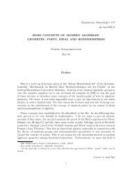
394 APPENDIX D . PROGRAM <strong>EDDYBL</strong>2 . Assuming the program is properly installed, you will see a messageinforming you that file eddybl.dat does not exist . The message asksif you want to create a new file named eddybl.dat . For this samplesession, you should answer yes by typing the letter Y or y followed bypressing the ENTER key .3 . Having performed Step 2, you will now be presented with the mainmenu (Figure D .l) on which ten options are listed . SETEBL hasbuilt-in default values for all input parameters that correspond toan incompressible (Mach .096) flat-plate boundary layer . When youeventually exit SETEBL, these data will be written into an Asciidata file named eddybl.dat . For this bench-mark case, if you selectedEnglish units as the default when you ran <strong>Program</strong> INSTL, you haveno need to change any data . However, this case must be done usingEnglish units . If you selected SI units as the default when you ranINSTL, you must change to English units . Type either a U or a u(for Units - note that the U is in reverse video on your display) andpress the ENTER key to make the change . The menu will change toindicate which units are in effect . Before exiting, you must generatetwo other data files, viz ., table.dat and input.dat that are neededin order to run <strong>Program</strong> <strong>EDDYBL</strong> .E D D 4 R L . . .America's Boundary Layer CodeDr . David C . Wilcox, DCW Industries(C) Copyright 1986-92 . All rights reserved .INPUT DATA ORGANIZERUrr;irn, % .0 I (,,f q2E-nglisli UnitsRequired Input :© MAIN PARAMETERSEDGE/YALL CONDITIONSQ INITIAL PROFILES® LIMITS SELECTION© WRITE DATA FILESOptional Input :© TURMLE7MCE MODEL® GAS PROPERTIES00LOGICAL LIMIT NUMBERSPROFILE PRINTINGR RESTART LAMSpecify option desired or © to eXit . . .Figure DA : Opening menu of <strong>Program</strong> SETEBL .4 . To generate these files, select the Write Data Files option . To dothis, type a Wor a w followed by pressing the ENTER key . After a
D.2 . GETTING STARTED QUICKLY 395short wait, you will be notified that the binary data file table.dat hasbeen successfully written. You are now presented with the followingquery in reverse video .Save the profiles in Ascii form? (X=eXit, Y=Yes, ENTER.=No) . . .If you desire a copy of the initial profiles to be saved in a disk filenamed setebl.prt for inspection at a later time, respond with a Y,ENTER sequence ; otherwise press the ENTER key. After you haveresponded to this query, a second query will appear, viz .,Display the profiles on the video? (X=eXit, Y=Yes, ENTER.=No) . . .If you want to see the profiles on your video display, respond accordingly.Otherwise, press ENTER . After you have responded, yourscreen clears again and a message appears indicating initial profilesare being generated . If you elected to display profiles on your videodisplay, they will now be displayed, a screen at a time . Press ENTERto advance to the next screen . Regardless of the options you have chosen,the precise values of the integral parameters for your computedinitial profiles are displayed . Finally, a message appears indicatingthe binary data file input.dat has been successfully written and thatyou must press ENTER in order to continue .5 . After you press ENTER, control returns to the main menu . At thispoint you have prepared all input-data files for the bench-mark run .Exit by typing an X, ENTER sequence .6. All that remains now is to run <strong>Program</strong> <strong>EDDYBL</strong> . <strong>Program</strong> outputwill be directed to a disk file named eddybl .prt . The file eddybl.prtsupplied on the distribution diskette contains the printoutfor the bench-mark run on an 80486/Weitek 4167 based microcomputer. Your results should agree to within several decimal places withthose in the sample printout . For reference, Table D.1 summarizes approximatecomputing times (including disk I/O) required for severalcomputers .7 . If you are using an IBM PC or compatible computer, you can generatea video and hardcopy plot of the computational results by running<strong>Program</strong> PLOTEB . Before executing this program, be sure tomodify the input-data file, ploteb .dat, as required for your system .Section D.8 describes all input parameters in the file .
396 APPENDIX D . PROGRAM <strong>EDDYBL</strong>Table D .1 :Computing time for the bench-mark caseComputer CPU (MHz) FPU (MHz) CPU Time(sec)Cray 2 - - 1GA-486L 80486 (25 .0) mW4167 (25 .0) 4Notebook 486DX 80486 (33 .0) 80487 (33 .0) 5GA-486L 80486 (25 .0) 80487 (25 .0) 6M-317B 80386 (33 .0) mW3167 (33 .0) 7VAX 8600 - - 10SPARC 7C601 (20 .0) 8847 (20 .0) 12Tandy 4000 80386 (16 .0) mW1167 (16 .0) 17DSI-785+ 68020 (25 .0) 68882 (25 .0) 19DSI-785+ 68020 (20 .0) 68882 (20 .0) 24DSI-020 68020 (16 .7) 68882 (16 .7) 29VAX 11/785 - - 36DSI-020 68020 (16 .7) 68881 (16 .7) 39VAX 11/750 - - 46DSI-020 68020 (12 .5) 68881 (12 .5) 52Tandy 4000 80386 (16 .0) 80287 ( 8 .0) 120Toshiba T1200 8086 (10 .0) 8087 (10 .0) 143Turbo 286 80286 (12 .0) 80287 ( 8 .0) 154M-317B 80386 (33 .0) None 232Tandy 4000 80386 (16 .0) None 624Turbo 286 80286 (12 .0) None 698TRS-80 Mod 16 68000 ( 6 .0) None 890SPECIAL NOTEAll input to <strong>Program</strong> SETEBL is case insensitive, i.e .,all commands and input can be entered in either upperor lower case .
D.3. INSTALLING SETEBL 397D .3Installing SETEBLTo use the supplied executable version of SETEBL on an IBM PC orcompatible microcomputer, including the default values specified for allinput-data parameters, simply copy the executable file to your workingdirectory. Otherwise, if you wish to change some of the default values, or ifyou are using a computer other than an IBM PC, the first step required toinstall <strong>Program</strong> SETEBL is to compile and link the program . The mainprogram is the file named setebl.for, and the various subroutines are listedin Section D.12 . All routines reference three include files, chars, comebland comeb2 . Section D .10 summarizes the commands required to compileand link <strong>Program</strong> SETEBL .The first step required to install SETEBL for your computeris to either copy the executable file to your workingdirectory or to compile and link <strong>Program</strong> SETEBL .In order to use <strong>Program</strong> SETEBL, you must first install it for yourparticular console . The program makes extensive use of reverse video, directcursor positioning, and some graphics characters . Since no uniformstandard exists for such console characteristics, the appropriate sequencesused by your console must be defined for <strong>Program</strong> SETEBL .D .3 .1Boot-Console InstallationIn order to install SETEBL on your main (or boot) console, you mustgenerate a binary data file named grafic.dat that contains all of the informationneeded by SETEBL . The source code for a program that generatesgrafic.dat customized for your console has been supplied as part of thissoftware package . The program is called INSTL, and the source is containedin instl.for . If you customize <strong>Program</strong> INSTL or if you are using acomputer other than an IBM PC, you must first compile and link <strong>Program</strong>INSTL . Then :The second step required to install SETEBL for yourconsole is to run <strong>Program</strong> INSTL .When you run <strong>Program</strong> INSTL, you will be given the option of specifyingwhether you want the default units to be English or SI . Make thechoice best suited to your needs . You will also have to specify the type ofcomputer you have and, in some cases, the type of console .When you have successfully run <strong>Program</strong> INSTL, the required binarydata file grafic.dat will be created and INSTL will print a message to that
398 APPENDIX D . PROGRAM <strong>EDDYBL</strong>effect . Whenever you wish to run SETEBL, simply make sure grafic .datis present in your directory . If it is not present, SETEBL displays a messageinforming. you that you are attempting to run an uninstalled version ofSETEBL and promptly terminates . If you are running <strong>Program</strong> SETEBLon an IBM PC based system, you must also install the ansi .sys driver .Thus,The third step required to install SETEBL on an IBMPC based system is to install the ansi.sys driver byadding the following command to your config .sys file .device=ansi . sysIf you have not previously had this command in your config.sys file, it willnot take effect until you re-boot your computer .D.3.2 Remote-Terminal InstallationFor a remote terminal whose characteristics are different from those of yourboot console, you can create another grafic.dat by making appropriatechanges to <strong>Program</strong> INSTL . The program is heavily commented, andcustomization should be straightforward .D .4Installing <strong>EDDYBL</strong>To use the supplied executable version of <strong>EDDYBL</strong> on an IBM PC orcompatible microcomputer, simply copy the executable file to your workingdirectory. Otherwise, if you wish to make program changes, or if you areusing a computer other than an IBM PC, the first step required to install<strong>Program</strong> <strong>EDDYBL</strong> is to compile and link the program . The main programis the file eddybl .for that also makes use of the include files common andcpuid. Be sure to link with the /e option for the Microsoft Fortran versionor the -pack option with SVS Fortran-386/Phar Lap to reduce the size ofthe executable file .The only step required to install <strong>EDDYBL</strong> for yourcomputer is to either copy the executable file to yourworking directory or to compile and link <strong>Program</strong> ED-DYBL .
D .5 . RUNNING A GENERAL CASE 399D .5Running a General CaseThis section explores, in detail, all of the salient features of the input-datapreparation utility, SETEBL . You will be guided through the variousmenus and, in the process, you will set up a constant-pressure boundarylayer computation for a Mach 1 freestream . For the case you willdo, freestream conditions are as follows .Total pressure, pt_ = 482.7 lb/ft2 (23112 N/m2)Total temperature, Tt_ = 468°R (260 K)Mach number, M,,, = 1The surface will be slightly cooled so that surface temperature is 95% ofthe adiabatic-wall temperature .Your goal is to initiate the computation at a plate-length Reynoldsnumber, Re .,, of one million and determine the point where the momentumthicknessReynolds number, Reg, is 6000 . You might want to do this, forexample, in order to provide upstream profiles for a Navier-Stokes computation. You know from a correlation of experimental data that whenRe ., = 1 .0 - 10 6 , the boundary layer has the following integral properties :Skin friction, cf .0038Shape factor, H 1 .80B.L . Thickness, 6 11.90Reynolds number, Reg 1500Finally, the surface is perfectly smooth, there is no surface mass transfer,and the k-w model will be used .D.5 .1 Preliminary OperationsTo perform this exercise, delete any existing eddybl.dat data file thatmight be in your directory. Although this is not generally necessary, forthe purposes of this section it will be easier if you begin with the defaultvalues .As with the bench-mark case of Section D.2, the very first step is torun <strong>Program</strong> SETEBL . If you have not installed the program, you will benotified with a brief message after which the program will immediately terminate. If this happens, go back to Section D.3 and perform the installationprocedure .Assuming the program is properly installed, you will see a messageinforming you that file eddybl.dat does not exist . You will be asked if youwant to create a new file named eddybl.dat . For this sample session, youshould answer yes by typing the letter Y followed by pressing the ENTERkey .
400 APPENDIX D. PROGRAM <strong>EDDYBL</strong>D .5 .2Units SelectionThis case can be done in either English or SI units . Examine the mainmenu to determine which units are in effect . If you wish to change units,type a U followed by pressing ENTER . The menu will reflect the changein units immediately. If you change your mind and wish to go back to theoriginal units, repeat the U, ENTER sequence . In the following sections,values are quoted in English units followed by corresponding SI values inparentheses .D.5 .3 Main ParametersAt this point, you will be presented with the main menu on which tenoptions are listed . Begin by entering the Main Parameters sub-menu .To enter this sub-menu, type an Mfollowed by pressing the ENTER key.Yet another sub-menu will now appear that gives you the choice of enteringinput data for either Freestream Conditions or Body Parameters .There is a third option that allows you to eXit . The latter option permitsyou to return to the previous menu . You will eventually do so, but firstyou will do some actual data preparation .Freestream Parameters . Type an F followed by pressing the EN-TER key to descend to the Freestream Conditions menu . You willnow see a display that includes seven of the primary quantities that specify freestream flow conditions, including freestream total pressure, totaltemperature, Mach number, shock-wave angle, and some turbulence parameters. The bottom row provides instructions on how to proceed . Pressthe ENTER key several times, for example, and you will see the arrowmove from one input variable name to the next . When you reach the lastvariable, pressing the ENTER key again will cause the arrow to move tothe uppermost variable . You may make as many passes through the list ofvariables as you wish .This particular menu includes a Help option to further explain the meaningof the more obscure input quantities . To display the Help menu, typean H followed by pressing the ENTER key. After reading this Help menu,pressing the ENTER key returns you to the Freestream Conditions dataentrymenu .Having returned from the Help menu, you will now exercise the Changeoption . First, position the arrow in front of Mach number . You accomplishthis by pressing ENTER twice . Now, type the letter C (for Change followed by pressing ENTER . The bottom line of the menu will now change .You are told to specify the new value, and that the FORMAT must be
D .5 .RUNNING A GENERAL CASEthe standard FORTRAN floating-point format E13 .6 . The default valueassigned to the Mach number is .096, corresponding to essentially incompressibleflow conditions . Change the Mach number to one by typing l .(the exponent E+00 is unnecessary but the decimal point is mandatory -this is normal FORTRAN 1/O) . As with all commands to SETEBL, nothingwill happen until you press the ENTER key. Before you do however,watch the line near the bottom of your display entitled Static Conditions .Keeping your eyes on the static conditions line, press the ENTER key. Ifyou have done this step correctly, the new static conditions should appearin place of the old . Also, if you look at the value assigned to the Machnumber you will find it has been changed to one .At this point, you can change any of the seven input quantities . Inaddition to Mach number, you must change total pressure and temperature .Press the ENTER key five times in order to position the arrow in frontof PT1, the total pressure . Using the change procedure, i .e ., type a Cfollowed by ENTER, insert the desired total pressure of 482 .7 lb/ft2 (23112 .N/m2 ) . You may enter 4.827e+02 (2 .3112e+04) or 4.827E2 (2 .3112E4),etc . if you wish . Note that your keyboard's normal destructive backspacekey can be used to correct typing errors . When your desired new totalpressure is correctly entered, press ENTER and the change will be made .Verify that the new value for PT1 shown on the display is 4.827000E+02(2.311200E+04) . If you made any mistakes, repeat the change operationuntil you get it right .Now press ENTER to position the arrow in front of TTl, the totaltemperature . Using the change procedure, change the value of TT1 to 468 .(260 .) . Don't forget the decimal point or else your total temperature will be.000468 ( .000260) . Verify that the new value for TTl shown on the displayis 4.680000E+02 (2.600000E+02) .If you have changed Mach number, total pressure and total temperaturecorrectly, the value listed below for static pressure will be very close to255 lb/ft 2 (12209 N/m 2 ) and the unit Reynolds number should be approximately 1.24 - 10 6 ft-1 (4 .07 - 10 6 rn-1 ) . Verify that your static conditionsmatch these two values . If they do not, find and correct any errors youhave made .Jot the values of static pressure and freestream unit Reynolds numberon a slip of paper for reference later . In general, knowing these values oftenhelps expedite preparation of your input data . Later on, we will see anexample of using both parameters .You have now finished this sub-menu . In order to exit, simply type anX followed by pressing the ENTER key. Note that, with the exception ofHelp menus for which only ENTER is needed, you return to the previousmenu by the X, ENTER sequence . Also, if you are ever in doubt about
402 APPENDIX D . PROGRAM <strong>EDDYBL</strong>what to do, look at the last line of the display for instructions .Body Parameters, Etc . Now you are back to the Main Parameterssub-menu that provides the options of altering freestream conditions, bodyparameters, etc . Descend to the Body Parameters sub-menu by typingthe letter B followed by pressing ENTER . You will be presented witha menu similar to the Freestream Conditions sub-menu . As before,press ENTER several times to move the arrow . Scan the input variabledefinitions and default values . Examine the Help menu . In other words,begin discovering that you already know most of what is needed in orderto operate SETEBL!There are only two input quantities you need to change, viz ., ISHORTand SSTOP . Because you are looking for the point where momentum thicknessReynolds number is 6000, you have no need for the long printout thatgives far more detail than you are interested in . Consequently, you shouldposition the arrow next to ISHORT and change its value to 0 . This is doneby typing C and a carriage return ; no value need be entered . As an experiment,you might want to try repeating this sequence . If you do, the valueof ISHORT will change back to 1 . Be sure you have changed ISHORT to 0after you finish experimenting .Turning now to SSTOP, use the ENTER key to position the arrow nextto SSTOP . This is the maximum value of plate length to which you willpermit computation to proceed . You are certain that momentum thicknessReynolds number will reach 6000 at a plate-length Reynolds number somewherebetween three and five million . Hence, you might want to terminateyour run when Reynolds number reaches five million . Referring to the unitReynolds number of 1 .24 . 10 6 ft-1 (4 .07 . 106 m-1 ) that you jotted downearlier, a quick computation shows that a plate-length Reynolds numberof five million occurs when plate length is 4.03 ft (1 .23 m) . Thus, changeSSTOP to 4 .03 (1 .23) .There are no further changes you need to make at this time on this menu,so you should now exit by typing X followed by pressing the ENTER key .At this point, you are done with the Main Parameters sub-menu . Inorder to return to the main menu, type another X followed by pressing theENTER key. Remember, nothing happens in SETEBL until you press theENTER key .D .5 .4Taking a Lunch BreakBefore continuing setting up a new run, you are going to simulate a lunchbreak . Imagine that it's time to break for lunch and the systems peopleupstairs are notorious for causing your VAX 8600 to crash during the lunch
D .5 . RUNNING A GENERAL CASE 403hour . Any file you leave open will be lost as a result of a crash . In orderto protect your work from such a disaster, simply exercise the exit optionby typing yet another X followed by pressing the ENTER key.Inspection ofyour directory will show that a new file named eddybl.dathas been created . Verify that the file exists at this time . If it does not, goback to Subsection D.5 .1 and omit the mistake you made that caused youto reach this point unsuccessfully.Now imagine you have returned from lunch, and your microcomputer(which never crashes during lunch because there are no system people tocause it to) is ready to continue serving your data processing needs . At thispoint, run <strong>Program</strong> SETEBL again . Because the data file eddybl.datexists, the program will go directly to the main menu .D.5 .5 Edge/Wall ConditionsFrom the main menu, you should now proceed to the Edge/Wall Conditionssub-menu by typing an E followed by pressing ENTER .This sub-menu contains five options, viz ., Pressure Distribution, HeatTransfer, Mass Transfer, Body Geometry and eXit . Type a P followed byENTER . The Pressure Distribution sub-menu explains that you mustprepare a file presur .dat that defines the pressure distribution . You mustprepare the file with an editor such as MS-DOS 5 .0's EDIT, DEC's EDT,UNIX's vi, etc . All you can change in this menu is the number of pointsyou plan on using . You will not change NUMBER because your run willhave constant pressure . Thus, you need to specify pressure at two valuesof plate length . Note that this menu describes in detail the contents andformat of presur .dat . Exit this menu with the usual X, ENTER sequence .Now go to the Heat Transfer sub-menu . You are presented with a descriptionof data file heater.dat that must be created with your own editor .Note that the adiabatic-wall temperature is given for your information andthe value listed should be 459 .4°R (255 .2 K) . The one parameter you canchange on this menu is KODWAL which determines whether you plan onspecifying surface heat flux or surface temperature . Type a C followed byENTER to change KODWAL . Note that the display now indicates temperatureis prescribed at the surface . Jot down the adiabatic-wall temperaturefor later reference . Exit this sub-menu by typing an Xfollowed by ENTER .Now go to the Mass Transfer sub-menu . This sub-menu describes afile, blocrv.dat, that must be prepared externally. You can alter the oneparameter NFLAG. The default value is 0, which means blocrv .dat is notrequired to prepare your edge and surface conditions . You have no need tochange its value for this application . Note that your display indicates thefile bloerv .dat will not be required . Exit this sub-menu .
404 APPENDIX D . PROGRAM <strong>EDDYBL</strong>Having exited the Mass Transfer sub-menu, you are now back at theEdge/Wall Conditions sub-menu . Proceed to the Body Geometrysub-menu . No, you didn't make a typing error . This is the same menu youjust completed. It has been included for planned future enhancements toSETEBL . Exit back to the Edge/Wall Conditions sub-menu with anX, ENTER sequence .The final option is to eXit . Do so by typing another X, ENTER sequence.You are now back at the main menu . You cannot continue until youhave prepared input-data files presur.dat and heater .dat (bloerv.dat isnot needed because NFLAG is 0) . Hence, it is time to exit SETEBL andsave all the work you have done so far .D .5 .6Preparing Edge/Wall Condition Data FilesThe easiest way to prepare the data files presundat and heater.dat (andbloerv.dat as well) is to use an editor such as EDIT, EDT, vi, etc . tomodify existing files from a previous run . That is why you left the filesfrom the bench-mark run in your directory. You can delete bloerv .datnow if you wish as it won't be needed .If you have followed all of the instructions correctly, you have the staticpressure of 255 lb/ft2 (12209 N/m2) and the adiabatic-wall temperatureof 459.4°R (255 .2 K) jotted down somewhere . Using your favorite editor,change presundat to the following :English Units :SI Units :0 .000000E 00 2 .550000E 021 .000000E 01 2 .550000E 020 .000000E 00 0 .000000E 000 .000000E 00 1 .220900E 041 .000000E 01 1 .220900E 040 .000000E 00 0 .000000E 00As explained in the Pressure Distribution sub-menu, the first twolines of this file are arc-length/pressure pairs presented in format (2E14.6) .The final line is the pressure gradient at the beginning and end of theinterval and the data are given in the (2E14.6) format also . You havespecified pressure at a plate length of zero and ten feet (meters) . Thisinterval must at least cover the planned integration range . The value of thepressure is the static pressure you jotted down earlier .
D.5 . RUNNING A GENERAL CASE 405Turning now to surface temperature, note that 95% of the adiabaticwalltemperature is approximately 436°R (242 K), which is the value youshould use . Use your editor to modify heater .dat as required, noting thatthe values of arc length at which you specify wall conditions must matchthe values used for the pressure distribution . As explained on the HeatTransfer sub-menu, this file must consist of the following four lines :English Units :0 .000000E 00 4 .360000E 02 0 .000000E 001 .000000E 01 4 .360000E 02 0 .000000E 000 .000000E 00 0 .000000E 000 .000000E 00 0 .000000E 00SI Units :0 .000000E 00 2 .420000E 02 0 .000000E 001 .000000E 01 2 .420000E 02 0 .000000E 000 .000000E 00 0 .000000E 000 .000000E 00 0 .000000E 00The format of the first two lines is (3E14 .6), while the last two lineshave format (2E14.6) . The first column for the first two lines is arc length,the second is wall temperature, and the third is surface heat flux . Notethat since you have chosen to specify surface temperature rather than heatflux, any value can be entered for the heat flux ; it won't be used in thecomputation . Similarly, if you choose to specify surface heat flux, the valueassigned to surface temperature is arbitrary . The third line gives surfacetemperature slope at the beginning and end of the interval, while the lastline gives surface heat flux slope . Of course, you are not limited to constantproperties in the most general case . You may prescribe as many as 50different values for edge pressure, surface temperature, etc .At this point, you have prepared all of the freestream conditions, bodyparameters, and (from an external editor) the two data files presur .datand heater .dat . Before reentering SETEBL, examine your directory. Inaddition to eddybl.dat, you should find another file eddybl.bak . Theformer is your most recent version of eddybl.dat . The latter is the versionyou created just before taking your lunch break. SETEBL always savesyour previous work in a file named eddybl.bak to provide you with a littleextra protection . You no longer need eddybl.bak, so delete it if you wish .
406 APPENDIX D. PROGRAM <strong>EDDYBL</strong>D.5 .7 Generating Edge/Wall ConditionsRun SETEBL again . When the main menu appears, use a W ENTERsequence to execute the Write Data Files option . A message will appearbriefly indicating edge conditions are being generated . When all computationsare complete, a message appears indicating a data file named table.dathas been successfully written . If you receive any other message,there are probably errors in the files you created with your editor in SubsectionD.5 .6 that you must correct before continuing . What you are doingin this step is executing a subroutine in <strong>Program</strong> SETEBL that accomplishestwo ends . First, you generate data file table.dat in binary formthat is used by <strong>Program</strong> <strong>EDDYBL</strong> . Second, you compute several parametersappearing in data file eddybl.dat that are needed in preparing initialprofiles .D.5.8Initial ProfilesIn addition to the message that table.dat has been successfully written,you also receive the messageSave the profiles in Ascii form? (X=eXit, Y=Yes, ENTER=No) . . .Since you have not yet prepared the data needed to generate initialprofiles, type an X, ENTER sequence . Upon returning to the main menu,you are now ready to go to the Initial Profiles sub-menu . Type an I followedby pressing the ENTER key . The sub-menu that appears has three options,viz ., Integral Parameters, Grid Parameters and eXit .Integral Parameters . Go to the Integral Parameters sub-menufirst by entering another I, ENTER sequence . Press ENTER once to positionthe arrow next to skin friction . Change the value to 0 .0038 in the usualmanner . Press ENTER again to move the arrow in front of boundary-layerthickness, 6 . For the conditions specified above, a quick calculation showsthat 6 for your unit Reynolds number is .0144 ft ( .004389 m) . Change thevalue of DELTA to 0 .0144 ( .004389) . Now move the arrow to shape factorand change its value to 1 .8 . Finally, move the arrow one more time tomomentumthickness Reynolds number and change its value to 1500 ., beingcareful to remember the decimal point. Inspect your work for possibleerrors . When you have made all entries correctly, exit this sub-menu .Grid Parameters . Now exercise the G option to enter the Grid Parameterssub-menu . The first quantity you should change is the initialstreamwise stepsize, DS . For this constant pressure case, you can use astepsize as big as triple the boundary-layer thickness . Hence, change thevalue of DS to 0.04 ft (0 .0122 m) . In order to start the computation at a
D .5 . RUNNING A GENERAL CASE 407plate-length Reynolds number of one million, the initial plate length (arclength) must be 0 .806 ft (0.246 m), a fact you can deduce by using thefreestream unit number of 1 .24 - 106 ft-1 (4.07 . 10 6 m-1 ) you jotted downearlier . Hence, change SI to 0.806 (0.246) . The next parameter is XK, thegrading ratio . A somewhat coarser grid can be used for this case than thedefault grid . Change the value to 1 .14 which corresponds to grid incrementsincreasing in a geometric progression at a 14% rate . Finally, change thenumber of grid points normal to the surface, IEDGE, to 51 . Again, inspectyour work for possible errors . When your entries are error free, exit thissub-menu . Having returned to the Initial Profiles sub-menu, you shouldnow exercise the exit option with the usual X, ENTER sequence in orderto return to the main menu .Generating Initial Profiles . As in Subsection D .5 .7, exercise theWrite Data Files option by entering a W, ENTER sequence . This willregenerate table.dat and you are again presented with the following message.Save the profiles in Ascii form? (X=eXit, Y=Yes, ENTER.=No) . . .If you desire a copy of the profiles, in Ascii form, to be sent to a disk filenamed setebl .prt that can be printed and/or examined with an editor afterexiting <strong>Program</strong> SETEBL, respond with a Y, ENTER sequence ; otherwisesimply press the ENTER key . After you have responded to this query, asecond query will appear as follows .Display the profiles on the video? (X=eXit, Y=Yes, ENTER.-No) . . .If you want to see the profiles on your video display, respond with a Y,ENTER sequence . Otherwise, press ENTER . After you have responded,your screen clears again and a message appears indicating initial profilesare being generated . If you elected to display profiles on your video display,they will now be displayed, a screen at a time . Press ENTER to view thenext screen . Regardless of the options you have chosen, the precise valuesof the integral parameters for your computed initial profiles are displayed .Finally, a message appears indicating the binary data file input.dat hasbeen successfully written and that you must press ENTER in order tocontinue .Notice that the value of the conventional sublayer coordinate, y+, forthe point nearest the surface is printed and its value is 0 .175 . SubroutineSTART will alert you if this value ever exceeds unity as <strong>Program</strong> <strong>EDDYBL</strong>requires the value of y+ nearest the surface to be less than 1 in order toremain numerically stable . If this ever happens, you must either increaseXK or IEDGE . When you press ENTER, control returns to the main menu .
408 APPENDIX D. PROGRAM <strong>EDDYBL</strong>You will receive a warning if you use the k-e model and the value of y+for the point nearest the surface is less than 0 .1 . Values smaller than 0 .1tend to slow the convergence rate for the k-e model, and may even causeyour run to crash .D .5 .9Selecting a Turbulence ModelIn order to select the k-w model, go to the Turbulence Model sub-menu .Type a T followed by ENTER, and you will find that the fourth quantitylisted is a flag called MODEL . Press ENTER three times to position thearrow in front of MODEL . Change its value to 0 by typing C followed byentering a 0 and pressing ENTER . Note that the highlighted bar below themenu now indicates you are using the k-w model without viscous correction(low-Reynolds-number) terms . Exit back to the main menu .For general reference, there are ten turbulence models implemented in<strong>EDDYBL</strong>, and the two input parameters MODEL and NVISC are usedto make the selection . The choices are as follows .MODEL NVISC-1 -0 00 11 01 12 02 12 22 32 42 5Turbulence ModelNone (Laminar Flow)k-w, viscous corrections excludedk-w, viscous corrections includedMultiscale, viscous corrections excludedMultiscale, viscous corrections includedk-c, Jones-Launder (1972)k-c, Launder-Sharma (1974)k,-c, Lam-Bremhorst (1981)k-c, Chien (1982)k-e, Yang-Shih (1993)k-c, Fan-Lakshminarayana-Barnett (1993)D .5 .10Logical Unit Numbers and Plotting FilesYour final input-data changes will cause printed output to go to your lineprinter rather than to disk file eddybl.prt . You will also verify that twodisk files named profil.dat and wall.dat will be created that can be used asstarting conditions for another program or as input to a plotting program .Go to the Logical Unit Numbers sub-menu by typing an L, ENTERsequence . The first parameter is IUNIT1 which, by default, is disk fileeddybl.prt . For Lahey, Microsoft or SVS Fortran versions, change its valueto 6 . For all other versions, use your normal operating system procedure to
D .5 . RUNNING A GENERAL CASE 409direct the contents of eddybl .prt to a line printer . Verify that the valuefor the parameter IUPLOT is some value other than 0 . If it is 0, changeits value to 10 (or any other convenient value excluding unit 15 and anypreviously assigned unit number) .Disk file wall.dat is written as an unformatted file, each record of whichcan be read by another FORTRAN program according to the followingprogram fragment .i=110 read(iunit) s(i),res(i),cfe(i),rethet(i),h(i),che(i),anue(i),pe(i),tv(i)if(s(i) .ne .-999 .) theni=i+1go to 10endifThe various quantities saved in disk file wall.dat are :Quantity Description Dimensionss s, arc length along surface ft (m)res Re Reynolds number based on s Nonecfe cf e = 2r, /pe ue, skin friction Nonerethet Ree, Reynolds number based on 0 Noneh H, shape factor Nonethe h/pe u,Cp , Stanton number Noneanue PTLSh/U,Cp, Nusselt number Nonepe Pe , edge pressure lb/ft2 (N /M2)tw T wall temperature °R (K)The first line of the file profil.dat generated by <strong>Program</strong> <strong>EDDYBL</strong>contains the streamwise step number, M, and the number of mesh pointsnormal to the surface, IEDGE . The format for this line is (216) . Theremainder of the file consists of IEDGE lines of data, format (12E11 .4),containing the following boundary-layer profile data, with quantities writtenon each line in the order listed . Note that for the k-c model, the specificdissipation rate, w, is defined byAlso, the tensor Tip is specific to the multiscale model and is given by (seeSubsection D.11 .2) :2_ 2PTij = ri7 + -okb ij - 3 P(k - e)bi7 (D .2)
410 APPENDIX D . PROGRAM <strong>EDDYBL</strong>Quantity Description Dimensionsy Distance normal to surface ft (m)u Horizontal velocity ft/sec (m/sec)T Temperature °R (K)p Density slug/ft' (kg/m3)k Turbulence kinetic energy ft 2 /seC2 (m2 /sec2 )Specific dissipation rate sec-1 (sec -1 )k - e Large eddy energyft 2 /seC2 (m 2 /sec2 )ft 2 /seC 2 (m2 /sec2 )T.. Large eddy xx-normal stressT.y Large eddy shear stressTyy Large eddy yy-normal stressft 2 /sec2 (m2 /sec2 )ft 2 /seC2 (m2 /sec 2)y+ Compressible sublayer-scaled distance Noneu+ Compressible sublayer-scaled velocity NoneYou may now exit back to the main menu . All of your input data areprepared and you are ready to run <strong>EDDYBL</strong> . Exit <strong>Program</strong> SETEBLwith a final X, ENTER sequence .D .5 .11Running the Boundary-Layer <strong>Program</strong>Run <strong>Program</strong> <strong>EDDYBL</strong> . Examination of program output reveals thatyour run didn't go far enough to determine the point where momentumthicknessReynolds number reaches 6000 . After the 30 steps you specifiedas the upper limit (the default value for IEND1- Main Parameters/GridParameters sub-menu), Ree is only 5200 . The plate length at the finalstation is only 2.69 ft (0 .82 m), so you allowed a large enough value, i .e .,4.03 ft (1 .23 m) for SSTOP.D.5 .12 Restart RunYou could go back to SETEBL, increase IEND1 to, say, 35, and simplyrerun <strong>EDDYBL</strong> . On an IBM PC/AT without an 80287, that's another8 or 9 minutes . Since you might not really want to take another coffeebreak while your job runs, you might prefer a less time-consuming solution .<strong>Program</strong> SETEBL provides such a possibility through its Restart option .Examine your directory and verify that <strong>Program</strong> <strong>EDDYBL</strong> has createda new file named output .dat . This file contains sufficient information torestart your program . Now, run <strong>Program</strong> SETEBL again . From the mainmenu, go to the Restart Run sub-menu by typing an R followed by pressingENTER. This menu will permit you to change IEND1, the maximumstreamwise step number, and SSTOP, the maximum value of arc (plate)
D .5 . RUNNING A GENERAL CASE 41 1length . Since your value for SSTOP is clearly large enough, you need onlychange IEND1 . With the usual procedure, change IEND1 from 30 to 35 .Now type X followed by pressing ENTER in order to return to the mainmenu . Before returning, you will receive a message in reverse video asfollows :"Do you wish to copy OUTPUT.DAT to INPUT.DAT? (Y/N). . ."Respond Yes by typing Y followed by pressing ENTER. At this point,for all but the VAX version, SETEBL will inform you that it first copiesinput.dat to a new file named input.bak . For all versions, SETEBL thencopies output.dat to input.dat . The point is, the final output of youroriginal run becomes input for the restart run . Additionally, your originalinput.dat has effectively been renamed as input.bak (VAX/VMS createsits own backup file so this file is unnecessary) . Upon completion of the copyoperation, control returns to the main menu (for the VAX version, you areinstructed to press ENTER to continue) . Exit <strong>Program</strong> SETEBL .At this point, data files eddybl.dat and input.dat have been modifiedas needed to continue your run from where you left off. The file table.datrequires no modification as SSTOP remains smaller than the top end of theinterval for which you have defined edge and surface properties . Had wemade SSTOP larger than 10, you would have to make appropriate changesto presur .dat and heater .dat to make sure edge and surface conditionsare defined at least up to the new value of SSTOP . You would then have toregenerate table.dat via the Write Data Files option (Subsection D.5 .?) .Now, run <strong>Program</strong> <strong>EDDYBL</strong> again . If you have made no errors, inspectionof the printout combined with a little interpolation shows that Reeis 6000 at a plate length of approximately 3 .15 ft (0 .96 m) .D.5.13Gas Properties and Profile PrintingAt this point, you have seen virtually all of <strong>Program</strong> SETEBL's menusand options . There are two sub-menus we didn't use in this exercise, viz .,Gas Properties and Profile Printing . Both menus are self explanatoryand operate in the same manner as the menus you've already explored .The Gas Properties menu allows you to modify thermodynamic propertiessuch as specific heat ratio, universal gas constant, and viscosity-lawcoefficients . The default values are set up for air with the Sutherland viscositylaw . You can implement a power-law viscosity relationship by settingSU = 0. Note that if you have a viscosity law of the form p = p,. efT" thenyou must set VISCON = It,,f and VISPOW = n + 1 .The Profile Printing sub-menu permits you to print velocity, temperature,turbulent energy, etc . profiles at specified streamwise stations . Pro-
412 APPENDIX D . PROGRAM <strong>EDDYBL</strong>gram <strong>EDDYBL</strong> always prints profiles at the final station . Also, whenever<strong>EDDYBL</strong> prints profiles, disk file output.dat is automatically written .D.5 .14 Selecting Laminar, Transitional or MurbulentFlow<strong>Program</strong> <strong>EDDYBL</strong> can run in three different modes corresponding to (1)pure laminar flow, (2) transition from laminar to turbulent flow, and (3)pure turbulent flow . The two test cases exercise <strong>EDDYBL</strong> in its pureturbulent mode in which integral parameters are specified and MOUND isset to 1 .To run in the transitional mode, simply select MOUND = 0 in theInitial Profiles/Integral Parameters menu . As a result, exact laminarvelocity and temperature profiles will be generated in conjunction withapproximate laminar profiles for the various turbulence-model parameters .The actual transition point is determined automatically by the model equationsand depends strongly upon the freestream values of k and w that arespecified in the Main Parameters/ Freestream Conditions menu interms of ZIOTAE and ZIOTAL . To obtain physically realistic transitionReynolds numbers you must include low-Reynolds-number corrections inthe k-w and multiscale models by setting NVISC = 1 in the TurbulenceModel sub-menu . Although the k-c models are capable of predicting transition,extremely small streamwise steps are needed with <strong>EDDYBL</strong>, andstable computation is very difficult to achieve .Even if you are not interested in transition, this mode is neverthelessuseful as it provides an alternate method for generating turbulent startingprofiles, e.g ., by starting laminar and running up to a desired value of Re o .Finally, to run <strong>EDDYBL</strong> as a pure laminar boundary-layer program,the turbulence model can be suppressed by setting MODEL to -1 in theTurbulence Model sub-menu . When this is done, turbulence model computationsare bypassed and no transition to turbulence occurs .D .6Applicability and Limitations<strong>Program</strong> <strong>EDDYBL</strong> applies to attached, compressible, two-dimensionaland axisymmetric boundary layers . The program computes properties ofturbulent boundary layers using the Wilcox (1988a) k-w model or theWilcox (1988b) multiscale model, including effects of surface roughness,surface mass transfer, surface curvature, and low-Reynolds-number corrections. The program also includes several low-Reynolds-number versions ofthe k-c model.
D.7. <strong>EDDYBL</strong> OUTPUT PARAMETERS 413Computations can be initiated either from turbulent starting profilesthat are generated from specified integral properties, or from laminar profilesthat are automatically generated .The k-w and multiscale models are very robust and can be integratedthrough transition from laminar to turbulent flow with and without low-Reynolds-number corrections . By contrast, the k-c model requires smallerstreamwise steps than the k-w and multiscale models, and, in general, cannotbe integrated through transition unless extremely small steps are taken .If integral properties are unknown and a k-c solution is desired, theoptimum procedure is to start laminar with the k-w model and integratethrough transition . Then, select the desired k-c model and use the Restartoption to continue the run .Finally, if numerical difficulties are encountered with the k-c model, trychanging the value of input parameter PSIEPS in the Turbulence Modelmenu . Table 7.2 lists the default value of this parameter (0E) ; its purposeis explained in Section 7 .3 .D .7<strong>EDDYBL</strong> Output ParametersThe following dimensionless quantities are printed in the profiles portionof <strong>Program</strong> <strong>EDDYBL</strong> output .Name Symbol/Equation Definitioni i Mesh point numbery/delta y/S Dimensionless normal distanceu/Ue ii/U, Dimensionless velocityyplus y+ = UTy/vw Compressible sublayer-scaled velocityuplus u+ = u"/u' Compressible sublayer-scaled velocityk/Ue**2 k/Ue Dimensionless turbulence energyomega veca/Ue Dimensionless dissipation rateeps/mu PT/P Dimensionless eddy viscosityL/delta k7/(w6) Dimensionless turbulence length scaleuv/tauw Txy /Tw Dimensionless Reynolds shear stressT/Te TIT' Temperature ratioThe following quantities are printed in the integral-parameter portionof <strong>Program</strong> <strong>EDDYBL</strong> output .
414APPENDIX D .PROGRAM <strong>EDDYBL</strong>Symbol Meaning English Units SI UnitsF Force pounds (lb) Newtons(N)L Length feet (ft) meters (m)M Mass slugs (sl) kilograms (kg)Q Heat flux Btu/second (Btu/sec) Watts (W)T Time seconds (sec) seconds (sec)0 Temperature ° Rankine KelvinsName Symbol/Equation Definition Dimensionsbeta Q = (2{/U ;dUe dg Pressure gradient parameter NoneCfe cfe = 2-rw/p,Ue Skin friction based on pe NoneCfw cfw = 2-r,/p.U.2 Skin friction based on p, Nonedelta 6 Boundary-layer thickness Ldelta* 6* Displacement thickness LdPe/ds d(Pe/p~U.)/ds Dimensionless pressure gradient NonedTe/ds d(Te/T,ef)/dg Dimensionless temperature grad . NonedUe/ds d(Ue IU~)lds Dimensionless velocity gradient NoneH H = 6*/B Shape factor Nonehdot h = Q./(T- Taw) Heat transfer coefficient QL -2 0 -1ledge N Total no . of mesh points in B.L . NoneItro Number of iterations Nonekmax ,Q*(pk) ,az/'rw Maximum turbulence energy NoneM rn. Streamwise step number NoneMe Me Edge Mach number NoneMue PC Edge molecular viscosity ML -1T-1Ne Ne Mesh point number at B.L . edge NoneNegtiv Number of points where k, w, c < 0 NoneNerror Number of points not converged NoneNskip No . of points below u+ = USTOP NoneNste h/p,Ue C, Stanton number based on pe NoneNstw h/p.UeCp Stanton number based on pw NoneNue PrLsh/9,Cp Nusselt number based on pe NoneNuw PrLShlp~Cp Nusselt number based on p, NonePe P C Edge pressure FL-2qw 9w Surface heat flux QL -2radius ra Body radius LRecov r Recovery factor NoneRedel* Reb. = peUe6*/pe Reynolds number based on 6* NoneRes Re, = peUesl tte Reynolds number based on s NoneRethet Reg = peU.B/pe Reynolds number based on 0 NoneRhoe pe Edge density ML -3rho*vw pwvw Surface mass flux ML -2T-1s s Arclength Ltauw 'rw Surface shear stress FL -2Te Te Edge temperature Otheta B Momentum thickness LUe Ue Edge velocity LT -1utau uT Friction velocity LT -1xi f = f0 PCUepero-ds Transformed streamwise coord. Lyplus y2 Value of y+ nearest the surface Nonez z Axial distance L
D.8 . PROGRAM PLOTEB : PLOTTING UTILITY 415D.8 <strong>Program</strong> PLOTEB : Plotting Utility<strong>Program</strong> PLOTEB creates video and hardcopy plots of skin friction, cf,or Stanton number, St, versus arc length, s, and a u+ versus y+ velocityprofile computed with <strong>Program</strong> <strong>EDDYBL</strong> on IBM PC's and compatibles .Input-parameter description :<strong>Program</strong> PLOTEB reads the following sixteen input parameters fromdisk file ploteb .dat in the order listed below . Integer quantities mustbe formatted according to (7x,i6) while floating-point quantities must beformatted as (7x,f6 .2) .mon Monitor type (see Appendix E)ifore Foreground color (see Appendix E)iback Background color (see Appendix E)nprin Printer type (see Appendix E)mode Graphics-mode flag for printers ; number of pens for plotters (seeAppendix E)metric Input arc length units flag-1 Input arc length is in meters0 Input arc length is in feet1 Convert from feet to metersideccf Number of decimal places for cf/St scaleidecx Number of decimal places for arc length scaleidecup Number of decimal places for u+ scaleisymb Symbol type for experimental data points0 Circle1 Triangle2 Square3 Diamondjstart Number of cf/St points to skip over at beginning of computation ;this is sometimes useful in order to skip over transient behavior atthe beginning of a computation. The sign also determines whatis plotted .> 0 Plot cf versus s< 0 Plot St versus skcyccf Increment between points to be plotted for cf/St versus skcycup Increment between points to be plotted for u+ versus y+kfilt 0 to suppress data filtering ; otherwise use filtering . The filteringalgorithm generates a smoothed curve .ksize Plot scaling factor . Using 100 yields a full-size hardcopy plot .Smaller values yield a hardcopy plot reduced by ksize per cent .
416 APPENDIX D. PROGRAM <strong>EDDYBL</strong>Thus, ksize = 50 yields a half-size plot .symsiz Size of experimental data symbols, in inchesNext, <strong>Program</strong> PLOTEB reads a single, free-formatted, line to indicatewhere hardcopy print is directed . This line comes immediately afterthe specified value for symsiz and defines the following five additional parameters.devid Device name of type character*4 ; valid devices are LPT1, LPT2,LPT3, COM1, COM2, COM3, COM4nbaud Baud rate for a serial port ; valid baud rates are 110, 150, 300,600, 1200, 2400, 4800, 9600parity Parity of type character*3 or character*4 for a serial port ; validparity settings are `even', `odd' and `none'nstop Number of stop bits for a serial port ; either 1 or 2lword Word length for a serial port ; either 7 or 8In addition to disk file ploteb .dat, an optional disk file named exper.dat containing measured skin-friction and velocity-profile data can beincluded . The first line of the disk file must contain the number of inputdata pairs with format (i6) . If no c f or St data are available, place a zeroon this line . If cf or St data are available, this line is followed by s-cf(or s-St) data pairs with format (2e11 .4) . Next, enter the data source ; asmany as twenty characters can be used . The final cf/St entry is the locationof the box citing the data source . Enter a 1 for upper left, 2 for upperright, 3 for lower right, and 4 for lower left (see Figure D .2) . The format is(7x,i6) . A similar sequence of input parameters follows for velocity-profiledata . The order of the data pairs is y+ first and u+ last . For example,the bench-mark case is an incompressible flat-plate boundary layer . Experimentaldata for this flow are given by Coles and Hirst (1969) . The sampleexper.dat included on the distribution diskette is as follows .51 .5978e 00 3 .4500e-032 .0899e 00 3 .3700e-032 .5820e 00 3 .1700e-033 .0741e 00 3 .1700e-033 .5663e 00 3 .0800e-03WIEGHARDTiposcf= 2124 .2400e 01 1 .4570e 018 .4800e 01 1 .6090e 01
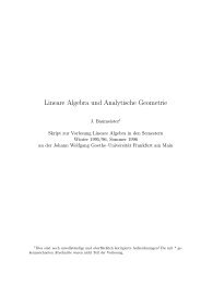
D.8 . PROGRAM PLOTEB : PLOTTING UTILITY 41 j<strong>Program</strong> Output : A video plot with two graphs (see Figure D.2) iscreated on the screen . When the plot is complete, the following messageappears:Hardcopy output (y/n)?Enter a y or a Yto create a hardcopy plot . Pressing any other key terminatesthe run without creating a hardcopy plot .Comments :1 .6950e 02 1 .7610e 013 .3910e 02 1 .9080e 015 .0860e 02 2 .0470e 016 .7822e 02 2 .1660e 018 .4779e 02 2 .2510e 011 .0173e 03 2 .3540e 011 .2716e 03 2 .4540e 011 .5259e 03 2 .5290e 011 .6954e 03 2 .5630e 012 .1193e 03 2 .5780e 01WEIGHARDTiposup= 1" The following is a sample input-data file, ploteb .dat, for a machinewith a standard VGA monitor and an HP DeskJet connected to serialport COM1 : .mon = 18 (Standard VGA monitor)ifore = 15 (Bright-white foreground)iback = 1 (Blue background)nprin = 2 (HP DeskJet)mode = 3 (300 dots per inch resolution)metric= 1 (Convert feet to meters)ideccf= 1 (One decimal place on Cf scale)idecs = 1 (One decimal place on s scale)idecup= -1 (Integers on u+ scale)isymb = 0 (Circles for experimental data)jstart= i (Skip no points)kcyccf= 3 (Plot every third Cf point)kcycup= 1 (Plot every u+ point)kfilt = 1 (Use filtering)ksize = 100 (Full size plot)
418 APPENDIX D . PROGRAM <strong>EDDYBL</strong>symsiz= .080 ( .08" experimental data symbols)'coma) , 9600 , )none) , 1 , 8The last line indicates the printer is connected to serial port COMl :and the port is set at 9600 baud, no parity, 1 stop bit and 8 data bits .If disk file ploteb.dat is not available, <strong>Program</strong> PLOTEB uses thefollowing set of default valuesmon = 18, ifore = 15, iback = 1, nprin = 24, mode = 39, ksize = 100,symsiz = .08, devid = `LPT1'Note that nbaud, parity,ports .3 03c f0nsiop and lword are not used for parallel0ONu +OO WIEGHARDT- COMPUTEDO°o .+ 0.6 0.e 1 .0 1 .2 3 .+x(m)OW+Figure D .2 : Sample plot created by <strong>Program</strong> PLOTEB .
D .9 . ADAPTING TO OTHER COMPILERS/SYSTENIS 419D.9 Adapting to Other Compilers/ SystemsIf you change computers or compilers, the appropriate modifications mayalready be included in the source code provided . If your Fortran compileris an ANSI-77 Standard compiler and supports most of the standard VAXextensions, only three categories of changes are needed .1 . You must determine the correct syntax for the include command .Then, note that the source code provided uses the VAX syntax . Makethe appropriate change throughout the source code for your compiler .Examples of VAX and other syntax are :Fortran CompilerVAX, SVS, Lahey, MicrosoftCray (UNICOS), SUNMicrosoft (older versions)SVS (older versions)Cray (COS)Include Syntaxinclude 'filename'include 'filename'$include : 'filename'$include filename*CALL FILENAMEColumn 12 . Change the value of icpu defined in the include file named cpuid .The values currently assigned are :icpu = 0 SVS Fortran (680x0, 80386, 80486)icpu = 1 Lahey/Microsoft Fortran (8088, 80x86)icpu = 2 VAX/VMSicpu = 3 SUN Fortran (68020, SPARC)icpu = 4 Cray (UNICOS)icpu = 5Silicon Graphics Iris3 .4 .The only other compiler-specific syntax differences are located in asubroutine called NAMSYS that appears in eddybl.for . This subroutineopens disk files depending upon the value of icpu . Make anychanges required for your system .Search the <strong>EDDYBL</strong> and SETEBL source code for occurrences oficpu to see if the correct action is taken for your compiler and/oroperating system . Make any changes required for your system .5 . Modify <strong>Program</strong> INSTL as required for your video display and/orcompiler-specific requirements .
420 APPENDIX D . PROGRAM <strong>EDDYBL</strong>D.10 Compile and Link CommandsThis section describes the commands required to compile and link <strong>Program</strong>sSETEBL, INSTL and <strong>EDDYBL</strong> for the various Fortran compilers supported. Be sure that you have selected the appropriate value for icpu inthe include file cpuid .ICPU = 0 : SVS Fortran-386 . . . Phar Lap and C3Special Comments : For the Phar Lap version, add the +w1167 optionto compile for a Weitek math coprocessor . Linker options for either fastlinkor 3861ink can be specified in an environment variable by including thefollowing in your autoexec .bat file . . .80387 versionset 3861ink=-1 libf28 libp28 -pack -maxr ffffh -s 40000Weitek versionset 3861ink=-1 libf28w libp28w -pack -maxr ffffh -s 40000Compile and Link :svs instl.forsvs eddybl .forsvs setebl .for edge .for grafic .for initil .for ioebl.for main0.for misc.forICPU = 0: SVS Fortran-020Special Comments : Use pload in place of load for Definicon PM-020and PM-030 boards .Compile and Link :load fc instl -lkload fc eddybl -lkload fc setebl edge grafic initilioebl main0 misc -lkICPU = 1 : Lahey Fortran . . . LF90Special Comments : None .Compile and Link :1f90 instl1f90 eddybllf90 setebl edge grafic initil ioebl main0 misc
D.10. COMPILE AND LINK COMMANDS 421ICPU = 1 : Lahey Fortran . . . F77L-EM/32Special Comments : None .Compile and Link :f7713 instl3861ink instlf7713 eddybl3861ink eddyblf7713 seteblf7713 edgef7713 graficf7713 initilf7713 ioeblf7713 main0f7713 misc3861ink setebl edge grafic initil ioebl main0 miscICPU = 1 : Lahey Fortran . . . F77LSpecial Comments : None .Compile and Link :f771 instloptlink instl ;f771 eddybloptlink eddybl ;f771 seteblf771 edgef771 graficf771 initilf771 ioeblf771 main0f771 miscoptlink setebl+edge+grafic+initil+ioebl+main0+misc ;ICPU = 1 : Microsoft FortranSpecial Comments : Using the /e option reduces executable file size .Compile and Link :fl instl.forfl eddybl .forfl /c setebl .for edge .for grafic .for initil .for ioebl.for main0.for misc .forlink setebl edge grafic initil ioebl main0 miscnul, /e;
422 APPENDIX D . PROGRAM <strong>EDDYBL</strong>ICPU = 2 : VAX FortranSpecial Comments : None .Compile and Link :for instllink instlfor eddybllink eddyblfor seteblfor edgefor graficfor initilfor ioeblfor main0for misclink setebl,edge,grafic,initil,ioebl,main0,miscICPU = 3 : SUN Fortran . . . SUN/OS or MS-DOS/SP-1Special Comments : Using the -03 option yields the maximum degree ofoptimization .Compile and Link :f77 instl .f -03 -o instlf77 eddybl.f -03 -o eddyblf77 setebl .f edge .f grafic .f initil .f ioebl .f main0.f misc.f -03 -o seteblICPU = 4 : Cray Fortran . . . UNICOSSpecial Comments : None .Compile and Link :cf77 -o instl instl .fcf77 -o eddybl eddybl .fcf77 -o setebl setebl .f edge .f grafic .f initil .f ioebl.f main0 .f misc .fICPU = 5: Silicon Graphics IrisSpecial Comments : None .Compile and Link :f77 -o instl instl .ff77 -o eddybl eddybl .ff77 -o setebl setebl .f edge.f grafic .f initil .f ioebl.f main0.f misc .f
D .11 . ADDITIONAL TECHNICAL INFORMATION 423D.11 Additional Technical InformationThe program uses the conventional Levy-Lees variables [see Hayes andProbstein (1959)] and much of the program notation follows that of Harrisand Blanchard (1982) . The numerical procedure is the Blottner (1974) variablegrid method augmented with an algorithm devised by Wilcox (1981b)to permit large streamwise steps . Section 7.3 of the main text provides anin-depth discussion of the algorithm . This section first presents the governingequations for mean-flow properties and all turbulence-model equationsimplemented in the program. Then, the transformed, nondimensional formof the equations is presented for the k-w and k-c models .D .11 .1Mean-Flow EquationsThe equations governing conservation of mass, momentum and mean energyfor all models are the same . For compressible two-dimensional (j = 0) andaxisymmetric (j = 1) boundary layers, the program uses body-orientedcoordinates (s, n), where s is arc length and n is distance normal to thesurface . The equations are as follows .TS (Pu) + i an= 0 (D .3)_8u _8u _ _dP 1 _a _auPlc as +pv an ds + ri an ~ (P an + PT (D .4)Pu Ts +pv an =u ds+'U (aaiiza 'j 'U 'UTn) + Pc + r an I ( PrL + PIT) On(D .5)The perfect gas law is used as the equation of state and the fluid is assumedcalorically perfect so thatP= and h = CPT (D .6)In Equations (D .3) through (D .6) : u and v are streamwise and normalmass-averaged velocity components ; P, P and h are fluid density, pressureand enthalpy ; p and PT are molecular and eddy viscosity ; r is specificReynolds shear stress ; e is turbulence dissipation rate ; PrL and PIT arelaminar and turbulent Prandtl numbers ; T is mass-averaged temperature ;R is the perfect gas constant ; and Cp is specific heat at constant pressure .
(1_k_424 APPENDIX D. PROGRAM <strong>EDDYBL</strong>D.11 .2 k-w and Multiscale Model EquationsFor both the k-w and multiscale models the dissipation, e, is given byc = (j*wk (D .7)where k is turbulence kinetic energy and w is specific dissipation rate . Theequations for k and w applicable to compressible boundary layers are asfollows .Pn as +Pv On - PT an -'a*P,k + r an [rj (P + 0'*ILT) an](D .8)_awTsw-.P7 _ au _au _1 _a _awPu as +Pv an = a k On - I3pw [c.' +f an] + r3 an [~ (P + 0/1T) an(D .9)For the k-w model, the Reynolds shear stress is given byaiipr = a* FATan(D .10)For the multiscale model, the Reynolds stresses are computed from thefollowing equations :_197 07 _ [a)Qy-~o,x+3(1-&-,l32 3 auPn as +Pv_ an+4fk -Ci,Q * PWTp8n(D .11)_aux _ao-x _ 2_auP'u - Cas +Pv (D [2(1 a) an 3 - +'~~ PT ani 'Q'pwQx.12)pu OQy + pv OQy - -2 - +[(1 &) 2a1 pr aii - * CIO PwO-y (D .13)as an 3 anwhere C1 is defined in terms of the ratio of large eddy energy (k - e) toturbulence kinetic energy according to3/2C 1 =1+4( k ek )and (k - c) satisfies the following equation .(D .14)a_aiikPu as (k-e)+Pv an(k-e)Pran-a*jowk~e3/2l(D .15)
D .11 . ADDITIONAL TECHNICAL INFORMATION 425The quantities a, and a y are the stress deviator components given interms of the normal Reynolds stress by~zax=pPi2-3k and ay =PP-3k (D .16)The various closure coefficients, viz ., a, #, /3*, (7, T*, &, and ~ aregiven by the following . First, we define the fully turbulent (subscript oo),incompressible (subscript i) values by,3ti = 3/40, ,3c*,. = 9/100, a = 1/2, v* = 1/2 (D .17)= 42/55, (3 = 6/55, y~ = 1/4, ~ = 0 or 1 (D .18)a OQ = Q* a~ = 1 (D .19)«>If low-Reynolds-number corrections are excluded, we simply use :a* =a 00, a = a, 0% = per, (D .20)If low-Reynolds-number corrections are included, we use the following :a * - a * ao + ReT/Rk°° 1 + ReT/Rk_ a o + ReT/RWa-ate .(a*) _,n1+ReT/&q* 5/183* +(ReTIRP)4001 -1- (ReTlRP) 4y = y~yo + ReT/Rk1 + ReT/Rkwhere m = 1 for the k-w model, m = 0 for the multiscale model, andao =,313, a,, = 1/10, ?'o = 2,3* a * /'Y,, R,3 = 8, Rk = 6 (D .22)00 0_ 27/10, k-w modelR`'' 3/4, Multiscale modelThe quantity ReT is turbulence Reynolds number defined bykReT = WVFinally, the compressible values of /3 and ,Q*r *are(D .21)(D .23)(D .24),3 = #_ I 1 - 3' ~ * F(M,)] ' ~* - # s [1 + ~*,V(Mt)] , * = 3/2 (D .25)
426 APPENDIX D . PROGRAM <strong>EDDYBL</strong>The compressibility function F(Mt )is given by_ 0, Mt < MtoF(Mt) - { Mt - Mi , Mt > Mto(D .26)where Mt - 2k/a 2 , a is the speed of sound, and Mt . is given byMt, = 1/4 (D .27)D.11 .3 k-c Model EquationsFor the k-E model the equations for k and E are :_8k _8k _ _8u1 _8 aklpu pv as + an-pl pe an - + -r-3- an [Ij (p + PT/O'k) (D .28)an_aF _aE E _a ii E 2 1 a _aEpe as +pv an = f1CEikPTan-f2CE2P k +PE+r~ an [~ (4 -f PT/U,) an](D .29)whereand the eddy viscosity isE = E + Eo (D .30)pT = Ci f ;,Pk2/E (D .31)<strong>Program</strong> <strong>EDDYBL</strong> includes six low-Reynolds-number versions of thek-E model . The models differ in the form of the damping functions ft,fl, f2, eo, E, in the values of the closure coefficients, and in the surfaceboundary condition imposed on E. The damping functions depend uponone or more of the following three dimensionless parameters .+ k2 _ k i/2 n _ u .rnReT = Ry, y - (D .32)Ev,v vThe damping functions, closure coefficients and surface boundary conditionon E for the six models are as follows .
D .11 . ADDITIONAL TECHNICAL INFORMATION 427Jones-Launder Model= e-2 .5/(1+ReT/50)f.f1=1f2 = 1 - 0 .3e-ReTawl 2ea = 2van (D .33)2022EE = 2vvT (,9n 2 )CEl = 1 .45, CE2 = 2 .00, C,, = 0 .09, Qk = 1 .0, o, E = 1 .3E=0 at n=0Launder-Sharma ModelfW = e-3.4/(1+ReT/50)afi=1f2 = 1 - 0 .3e-ReTaaw 2e a = 2v ( an ) (D .34)a2u2E = 2vvT (an 2 )CEl = 1 .44, CE2 = 1 .92, Cu = 0 .09, Qk = 1 .0, Q E = 1 .3e`=0 at n=0Lam-Bremhorst Model= fA ( 1 - e-0.0165.)2 (1 + 20.5/ReT)f1 = 1 + (0 .05/f,,)3f2 = 1 - e-Re z .C O =0 (D .35)E=0ca = 1.44, CE2 = 1 .92, C,, = 0 .09, Qk = 1 .0, o,E = 1 .32at n=0E-vane
428 APPENDIX D. PROGRAM <strong>EDDYBL</strong>Chien ModelfN = 1 - c-0.0115y+f1 = 1f2 = 1 - 0.22e-(ReT/s)2co = 2v2 n(D .36)E = -2v z e-y + 1 2nCEI = 1 .35, CE2 = 1 .80, Cp = 0 .09, vk = 1 .0,E=0 at n=0Yang-Shih Model_ [1 - exp (-1 .5 - 10-4Ry - 5 . 10 -7Ry 10- 10Ry )] 1/2f~(1 -}- 1/ ReTf1 = ReT / ( 1 + ReTf2 = ReT/ 1 + ReTEo =0(D2.37)a2uE = vvTCan2~CE1 = 1 .44, C E2 = 1 .92, C,, = 0 .09, 0-k = 1 .0,/ 2E=2v1 aO at n=0Fan-Lakshminarayana-Barnett Modelfo - 0 .4-+- - 0 .4V) (1-e- R a /42 .ss J 1 3ReT C1 eTf1-1f2 = [1 - 0 fw2.22e-(ReTl6)2]Ryfw - expp ~--~ 1-e Ry/20/ (D .38)+ 2.30 8 .893Je o = 0E=0CEl = 1 .39, CE2 = 1 .80, Cm = 0 .09, 0-k = 1 .0,aEan =0 at n=0
D .11 . ADDITIONAL TECHNICAL INFORMATION 429D .11 .4 Transformed EquationsThe boundary-layer equations are singular at the leading edge of a body.As noted above, the program uses conventional Levy-Lees variables (~, 71)to remove this singularity . Body oriented physical coordinates (s, n) arerelated to transformed coordinates (~, ij) according todf = Peu,Per2l ds and dii = Pue(ro) j do(D .39)where r o is body radius and subscript e denotes boundary-layer edge .Equivalently, we can write~(S) = sf Pefeper o9 ds0and q(s, n) =where t is the transverse curvature defined bynPe ,ue-77 0 PeI'l, P t. . do (D .40)t = r (D .41)r oThe relations between derivatives in the physical (s, n) and transformed(~, r!) coordinate system are as follows :Cas)na= Peueheroi ( '9~+ C as )n '971)£8n 27 CPe)C19 Peuerot 7The dependent variables are also transformed according to :(D .42)(D .43)U,~ ~(~~ ~l) =T TeTeN, rl) = ~ 2j(D .44)Peue ero [F C as) + Pv~, ]k 2~w (~ 2~ZK( , rl) = u2W(f rl) = u2E ~!) = i4e e eThe transformed equations for the k-w and k-c models can then beexpressed as follows .aF2~a + r~VaV + F = 0 (D .45)
430 APPENDIX D . PROGRAM <strong>EDDYBL</strong>2~Ff +V~~ -,97 [t 2'L(1+MT) ~~l+p(F2-O-1)=0 (D .46)k-w Model :2~F a +Va 0 77 -a tzjL PrL + Pr 8Ol T~ 7J_dt2 (2F) 2aPef~2~F a~ + V a,, 77 I t2i L (1 0-*AT) aK]+ C917OF+2aFK )- t 2i LAT + '~ WK = 0 (D .48)aye 77~o92~Faw +Vaw - a 2 ;L(1+O'AT) ~Wa7, at a 77It a~ 1+2(Q - 1)FW - a t 2i KLNT (aF)2 71+ lj IW+~ PefoV K tj _aF] W=OPeAer2j E (1 +(D .49)2~Pe Kl-IT __ ~,E2 L(1+ O)2W' £ = ,Q*KW, £o = 0,(D .50)k-e Model :2~FAT ) 1K]7i a~ + V as It 2i L C1 + Qk az++2,QFh-t2jLEcT1IF)zJ . (£+£o)=0 (D .51)a~ Pe~e r0
D.11 . ADDITIONAL TECHNICAL INFORMATION 4312 F i9~ + V'97 -'9'ql tzjL Cl + AT aEl) a7z+2(2/3-1)FF-CElfi-OLATC5F)+ CEzfz Ez - = 0PeAeroj K(D .52)21Pe K 2 __ _A _2~ __ _A z (2~) 2PT = C,,.fN L(1 Fo~,E2 + O)zF' U3 ue Eo, E U4 Peu spera~ E(D .53)The quantities a, o and L are defined by7e - - 2f, du ea- C T e ~ =P fe'pehe d L=and the following dimensionless quantities have been introduced :roP.U.PrA2'i+l' A rPe = W Pe TepeTe =Poo h~r/fir(D .54)(D .55)pr W= W FE=F-poojJ~ A' poo pr AZA ' poo fr r AziFinally, note that subscript oo denotes freestream flow condition, A isreference length, Tr is the reference temperature defined asa(D Tr = U./CP.56)and pr is the value of p for T = Tr .
432APPENDIX D .PROGRAM <strong>EDDYBL</strong>D .12Software Package ModulesBoundary-Layer <strong>Program</strong> Source :eddybl .forcommoncpuidData-Preparation Utility Source :setebl .foredge .forgrafic .forinitil.forioebl.formain0.formisc .forcharscomeblcomeb2Installation <strong>Program</strong> Source :instl.forBench-Mark Case Input Data :blocrv .datheater .datpresur .datSource code for <strong>Program</strong> <strong>EDDYBL</strong>Include file for <strong>Program</strong> <strong>EDDYBL</strong>Include file specifying CPU typeSource code for the main programSource code for edge condition menusSource code for reading graphics dataSource code for initial profile menusSource code for I/O subroutinesSource code for main input parameter menusSource code for miscellaneous menuse file for <strong>Program</strong> SETEBLIncludIncludInclu e file for <strong>Program</strong> SETEBLe file for <strong>Program</strong> SETEBLSource code for <strong>Program</strong> INSTLMass-transfer, body-curvature data fileHeat-transfer, surface-temperature data filePressure-distribution data filePlotting Files :exper.datploteb .datExperimental data file for plotting programPrimary plotting-program data fileBench-Mark Case Output :eddybl.prt Output from bench-mark test caseExecutable Files for IBM PC and Compatible Microcomputers :eddybLexe <strong>Program</strong> <strong>EDDYBL</strong>instLexe <strong>Program</strong> INSTLploteb.exe <strong>Program</strong> PLOTEBsetebl .exe <strong>Program</strong> SETEBL