DC Circuits Lab - Web Physics
DC Circuits Lab - Web Physics
DC Circuits Lab - Web Physics

Create successful ePaper yourself
Turn your PDF publications into a flip-book with our unique Google optimized e-Paper software.
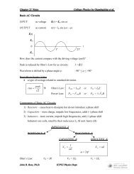
Pre-<strong>Lab</strong>:<br />
<strong>Physics</strong> 251 <strong>Lab</strong>oratory<br />
<strong>DC</strong> <strong>Circuits</strong> I: Simulation<br />
Do the lab prep on the web. Please bring in the equations you derive in question #2 on the lab<br />
prep (or section 3 of this lab) to turn in at the beginning of the lab. This homework will be worth<br />
4 of the 10 points for this lab.<br />
Introduction<br />
This lab deals with direct-current circuits that consist of different combinations of batteries<br />
and resistors. Specifically, you will be using Kirchoff’s Laws to study two simulated direct-current<br />
circuits. You will use what you have learned about spreadsheets in the previous lab to make<br />
calculations of circuit behavior for various values of these resistances, voltages, etc., in these<br />
circuits.<br />
Equipment/Supplies<br />
Macintosh computer with Microsoft Excel software<br />
Simulations are in the 251 folder in a file labeled: “Kirchoff Simulation.”<br />
Section 1<br />
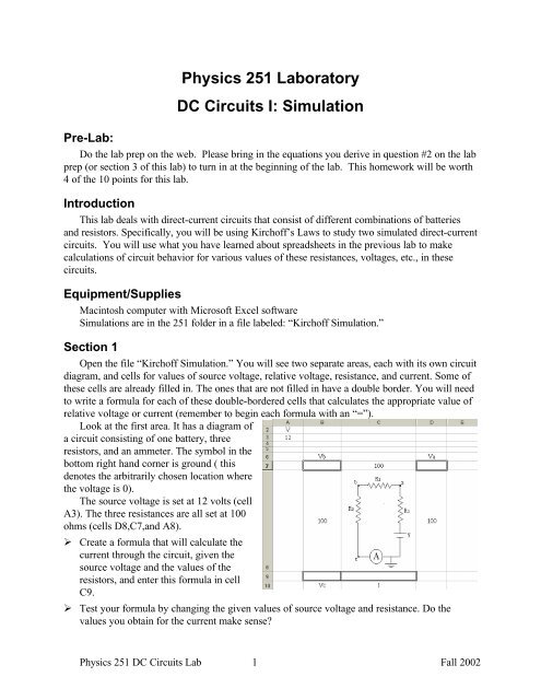
Open the file “Kirchoff Simulation.” You will see two separate areas, each with its own circuit<br />
diagram, and cells for values of source voltage, relative voltage, resistance, and current. Some of<br />
these cells are already filled in. The ones that are not filled in have a double border. You will need<br />
to write a formula for each of these double-bordered cells that calculates the appropriate value of<br />
relative voltage or current (remember to begin each formula with an “=”).<br />
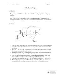
Look at the first area. It has a diagram of<br />
a circuit consisting of one battery, three<br />
resistors, and an ammeter. The symbol in the<br />
bottom right hand corner is ground ( this<br />
denotes the arbitrarily chosen location where<br />
the voltage is 0).<br />
The source voltage is set at 12 volts (cell<br />
A3). The three resistances are all set at 100<br />
ohms (cells D8,C7,and A8).<br />
‣ Create a formula that will calculate the<br />
current through the circuit, given the<br />
source voltage and the values of the<br />
resistors, and enter this formula in cell<br />
C9.<br />
‣ Test your formula by changing the given values of source voltage and resistance. Do the<br />
values you obtain for the current make sense?<br />
<strong>Physics</strong> 251 <strong>DC</strong> <strong>Circuits</strong> <strong>Lab</strong> 1 Fall 2002
Section 2<br />
Continue to work with the first circuit, focusing on the three empty cells available for voltage<br />
calculations (D7,B7, and B9). Create a formula for each of these cells that calculates the voltage<br />
relative to ground at points a, b, and c. These formulas should all depend on the source voltage,<br />
the individual resistance values, and the value of the current.<br />
‣ Again, test your formulas by changing the given values.<br />
‣ Before moving ahead please answer the questions on the back page referring to Section 2.<br />
Section 3<br />
The second area has a circuit that is somewhat more complicated than the previous one. A<br />
branch has been added as well as two additional batteries. There are now three currents present<br />
that you will need to create formulas for (cells H3, I3, and J3). These are the formulas that<br />
you calculated before class and should be in terms of the three source voltages and the three<br />
resistance values.<br />
‣ Once again, test your formulas by varying the values for the source voltages and resistances.<br />
Do your formulas hold up?<br />
‣ Create a few more cells<br />
that calculate other<br />
testable values.<br />
‣ Calculate the voltage<br />
difference between the<br />
bottom wire and the node<br />
at the top-center using<br />
three different paths.<br />
‣ Please answer the<br />
questions on the back<br />
page that refer to Section<br />
3.<br />
<strong>Physics</strong> 251 <strong>DC</strong> <strong>Circuits</strong> <strong>Lab</strong> 2 Fall 2002
<strong>Physics</strong> 251 <strong>Lab</strong>oratory<br />
<strong>DC</strong> <strong>Circuits</strong> - 2<br />
Pre-<strong>Lab</strong>: Please do the lab prep on the web.<br />
Introduction<br />
In this lab, you will set up a real two loop circuit consisting of three resistors and three<br />
batteries. You will use a voltmeter, an ammeter, Ohm’s law and Kirchoff’s laws to find values of<br />
resistance and current.<br />
Equipment/Supplies<br />
3 voltage sources Wires<br />
3 resistors Multimeter<br />
Section 1<br />
Use your multimeter to measure the resistances of the three resistors, and the voltages<br />
provided by the three voltage sources. The actual values may differ from the nominal values by<br />
several percent.<br />
Section 2<br />
Now set up a two loop circuit as shown in<br />
the picture, using the three batteries and the three<br />
resistors. Be mindful of the polarity of the<br />
batteries. Be sure your circuit duplicates the one<br />
in the diagram. Using the spreadsheet you<br />
developed last week, calculate the current in each<br />
branch of the circuit, including the direction, as<br />
well as the voltage across each resistor. Record<br />
these values. Now use the multimeter to directly<br />
measure the current and voltage through each<br />
resistor. Do these values agree with the ones you<br />
obtained using Kirchoff’s laws?<br />
Section 3<br />
Use your multimeter to measure the voltages<br />
provided by the three sources without removing<br />
them from the circuit. Do your new values agree with you old values? If not, use your new<br />
values in the spreadsheet, and see if the agreement between calculated and measured currents has<br />
improved.<br />
<strong>Physics</strong> 251 <strong>DC</strong> <strong>Circuits</strong> <strong>Lab</strong> 3 Fall 2002
Name ___________________________________ Date _______________________<br />
<strong>Lab</strong> Partners __________________________________________________________<br />
Section 2<br />
<strong>DC</strong> <strong>Circuits</strong> I - Simulation<br />
Results<br />
1. What is the current through the circuit? I:______________________________________<br />
What relative voltages did you obtain for points a, b, and c, using the given values?<br />
V(a): V(b): ______ V(c):___<br />
2. Now, double the source voltage and halve the value of the first resistor.<br />
What is the current through the circuit? I:______________________________________<br />
What are the relative voltages?<br />
V(a): V(b): ___ V(c): ___<br />
3. Is there anything unique about any of the relative voltages at point a, b, or c? Why is this so?<br />
_<br />
Section 3<br />
1. What values did you obtain for the three currents, using the given quantities?<br />
I1: I2: I3:<br />
2. What is the difference in voltage between the bottom wire and the top/center node, using the<br />
given values?<br />
<strong>Physics</strong> 251 <strong>DC</strong> <strong>Circuits</strong> <strong>Lab</strong> 4 Fall 2002
3. Now, change the values of the three resistors to what ever you want and report the currents<br />
again.<br />
R1: R2: R3:<br />
I1: I2: I3:<br />
Overall – <strong>DC</strong> <strong>Circuits</strong> 1<br />
Explain to “the Boss” why we want to use excel to simulate this circuit before we actually build<br />
it? What happens to I1 when we change the value of R1?<br />
__________________<br />
__________________<br />
What was good about this lab and what would you do to improve it?<br />
__________________<br />
__________________<br />
<strong>Physics</strong> 251 <strong>DC</strong> <strong>Circuits</strong> <strong>Lab</strong> 5 Fall 2002
Name ___________________________________ Date _______________________<br />
<strong>Lab</strong> Partners __________________________________________________________<br />
Section 1<br />
<strong>DC</strong> <strong>Circuits</strong> - 2<br />
Results<br />
Make these measurements before you build the circuit.<br />
1. What are the measured values of the resistors?<br />
R1_______ R2_______ R3________<br />
2. What are the measured values of the voltage sources?<br />
Section 2<br />
V1_______ V2_______ V3________<br />
Input the above values into your spreadsheet to obtain calculated values.<br />
1. What are the calculated values of current?<br />
I1_______ I2________ I3_________<br />
2. What are the measured values of current?<br />
I1_______ I2________ I3_________<br />
3. What are the calculated values of voltage drop across each resistor?<br />
V(R1)_______ V(R2)_________ V(R3)___________<br />
4. What are the measured values of voltage drop across each resistor?<br />
V(R1)_______ V(R2)_________ V(R3)___________<br />
5. Do the calculated values agree with the directly measured ones?______________<br />
<strong>Physics</strong> 251 <strong>DC</strong> <strong>Circuits</strong> <strong>Lab</strong> 6 Fall 2002
Section 3<br />
1. What are the measured values of the voltage sources while they are in the circuit?<br />
V1_______ V2________ V3_________<br />
2. Use the new values for voltages V1, V2 and V3 in the spreadsheet to calculate current<br />
and voltage drop across R1, R2 and R3<br />
3. Explain to “the boss” why the measured values of the voltages and currents in the<br />
circuit are different than the calculated values.<br />
______________________________________________________________________________<br />
______________________________________________________________________________<br />
______________________________________________________________________________<br />
Overall – <strong>DC</strong> <strong>Circuits</strong> 2<br />
What was good about this lab and what would you do to improve it?<br />
__________________<br />
__________________<br />
<strong>Physics</strong> 251 <strong>DC</strong> <strong>Circuits</strong> <strong>Lab</strong> 7 Fall 2002