
Create successful ePaper yourself
Turn your PDF publications into a flip-book with our unique Google optimized e-Paper software.
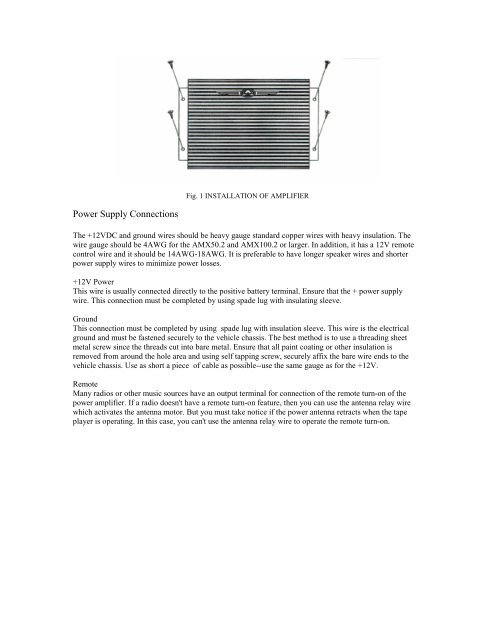
Fig. 1 INSTALLATION OF AMPLIFIER<br />
Power Supply Connections<br />
The +12VDC and ground wires should be heavy gauge standard copper wires with heavy insulation. The<br />
wire gauge should be 4AWG for the <strong>AMX</strong><strong>50.2</strong> and <strong>AMX</strong><strong>100.2</strong> or larger. In addition, it has a 12V remote<br />
control wire and it should be 14AWG-18AWG. It is preferable to have longer speaker wires and shorter<br />
power supply wires to minimize power losses.<br />
+12V Power<br />
This wire is usually connected directly to the positive battery terminal. Ensure that the + power supply<br />
wire. This connection must be completed by using spade lug with insulating sleeve.<br />
Ground<br />
This connection must be completed by using spade lug with insulation sleeve. This wire is the electrical<br />
ground and must be fastened securely to the vehicle chassis. The best method is to use a threading sheet<br />
metal screw since the threads cut into bare metal. Ensure that all paint coating or other insulation is<br />
removed from around the hole area and using self tapping screw, securely affix the bare wire ends to the<br />
vehicle chassis. Use as short a piece of cable as possible--use the same gauge as for the +12V.<br />
Remote<br />
Many radios or other music sources have an output terminal for connection of the remote turn-on of the<br />
power amplifier. If a radio doesn't have a remote turn-on feature, then you can use the antenna relay wire<br />
which activates the antenna motor. But you must take notice if the power antenna retracts when the tape<br />
player is operating. In this case, you can't use the antenna relay wire to operate the remote turn-on.