SNS Exit Sign Install ELF600_ELF600G SNSDOC ... - Primex Wireless
SNS Exit Sign Install ELF600_ELF600G SNSDOC ... - Primex Wireless
SNS Exit Sign Install ELF600_ELF600G SNSDOC ... - Primex Wireless

You also want an ePaper? Increase the reach of your titles
YUMPU automatically turns print PDFs into web optimized ePapers that Google loves.
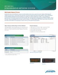
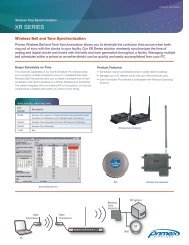
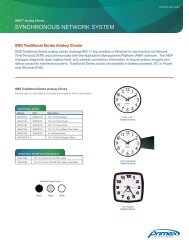
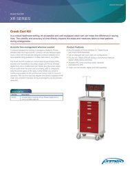
INSTALLATION INSTRUCTIONS<br />
Model <strong>ELF600</strong>, <strong>ELF600</strong>G <strong>SNS</strong> PHOTOLUMINESCENT EXIT SIGN<br />
READ AND FOLLOW ALL SAFETY INSTRUCTIONS<br />
Safety Instructions<br />
• External Illumination source required.<br />
• External illumination source must be reliable and supplied by a circuit not controlled by automatic timers or sensors and whose<br />
controls are accessible only to authorized personnel.<br />
• External illumination source is to be energized at all times during building occupancy.<br />
• Lighting levels at the sign faces(s) should be confirmed after any change in external lighting types or level.<br />
• <strong>Install</strong> this sign indoors only, where not exposed to direct sunlight, liquid spray, or temperatures outside the range of +10 to<br />
40 C.<br />
Maintenance<br />
• Any damage to the sign or concerns about performance should be brought to the attention of <strong>Primex</strong> <strong>Wireless</strong> or the<br />
representative from whom the sign was purchased.<br />
• The photoluminescent exit sign is designed to operate automatically. The charging light source must illuminate the face(s) of<br />
the sign with at least 5-foot candles (54 lux) of unfiltered light at all times during the building occupancy to ensure that the sign<br />
will remain legible for at least 90 minutes from a distance of 75 feet during an emergency.<br />
CAUTION: Minimum 5 foot-candle (54 lux) of external fluorescent illumination must be present on the sign face at all times<br />
during building occupancy.<br />
SAVE THESE INSTRUCTIONS FOR FIRE SAFETY INSTRUCTIONS.<br />
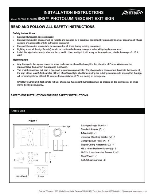
PARTS LIST<br />
Figure 1<br />
<strong>Exit</strong> <strong>Sign</strong> (Single Sided) - 1<br />
Standard Adapter (C) - 1<br />
T-Bracket (I) - 1<br />
Universal Mounting Bracket (M) - 1<br />
Canopy (Cover Plate) (K) - 1<br />
Sloped Ceiling Adapter (S) (Q) - 1<br />
M3 x 16mm Machine Screws (J) - 2<br />
#8-32 x 1 inch Machine Screws (L) - 2<br />
Allen Wrench - 1<br />
Self-Adhesive Arrows - 2<br />
<strong>Primex</strong> <strong>Wireless</strong> | 965 Wells Street Lake Geneva WI 53147 | Technical Support (800) 404-8112 | www.primexwireless.com
SIGN RECONFIGURATION<br />
1. If configuring for ceiling mounting, loosen the set screws (F) at the top and bottom corner connectors (E) on one side of the<br />
exit sign.<br />
Figure 2<br />
2. Pull on the vertical frame (B) and the corner<br />
connectors to remove them from the rest of the<br />
exit sign.<br />
3. If configuring for edge mounting, loosen the set<br />
screws (F) on the top corner connectors (E) of the<br />
exit sign.<br />
4. Pull on the vertical frame (A) and the corner<br />
connectors to remove them from the rest of the<br />
exit sign.<br />
5. Loosen the set screw (D) inside the standard<br />
adapter (C) and then slide the standard adapter<br />
(C) into the horizontal fame (A) for ceiling<br />
mounting or into the vertical frame (B) for edge<br />
mounting and tighten the set screw (D) to secure<br />
it.<br />
6. If exchanging the photoluminescent sign (G), slide<br />
the signs in and out of the open side of the exit<br />
sign after completing steps 1 and 2 outlined above.<br />
7. Reverse steps 1, 2, or 3 and 4 to reassemble the<br />
exit sign.<br />
Directional Arrow Application<br />
Use the tiny dots on the left and right side of the<br />
sign to accurately position the self-adhesive<br />
arrows as required.<br />
CEILING MOUNTED (DIRECTLY TO CEILING OR SUSPENDED CEILING T BAR)<br />
EDGE MOUNTED (DIRECTLY TO WALL AT 90 DEGREE ANGLE)<br />
1. Position the standard adapter on top of the exit sing for ceiling mounting or on one side of the exit sign for edge mounting<br />
(see <strong>Sign</strong> Reconfiguration – Figure 2).<br />
2. Attach T-bracket (I) to ceiling to T bar or wall using two #6 screws and wall plugs if appropriate (not supplied).<br />
3. Using the supplied Allen wrench back off the set screw on the face of the standard adaptor (C) and slide the standard<br />
adaptor (C) together with the exit sign already attached over T-bracket (I).<br />
4. Tighten the set screw loosened in step 2 to secure the exit sign on the T-bracket (I)<br />
Figure 3<br />
<strong>SNS</strong>DOC-028 201208reva <strong>Primex</strong> <strong>Wireless</strong> | 965 Wells Street Lake Geneva WI 53147 | Technical Support (800) 404-8112 | www.primexwireless.com
RETROFIT CEILING MOUNTED (OVER EXISTING OCTAGON BOX)<br />
RETROFIT EDGE MOUNTED (OVER EXISTING OCTAGON BOX WALL AT 90 DEGREE ANGLE)<br />
1. Position the standard adaptor on top of the exit sign for<br />
ceiling mounting or on one side of the exit sign for edge<br />
mounting (see <strong>Sign</strong> Reconfiguration Figure 2).<br />
2. Attach-the universal mounting plate (M) to the octagon box<br />
(P).<br />
3. Attach the T-bracket (I) to canopy (K) using the supplied M3 x<br />
16mm machine screws.<br />
4. Attach the canopy/T-bracket assembly to the universal<br />
mounting plate using #8-32 x 1 inch machine screws (L).<br />
5. Using the supplied Allen wrench back off the set screw on the<br />
face of the standard adaptor (C) and slide the standard<br />
adaptor (C) together with the exit sign already attached over<br />
T-bracket (I).<br />
6. Tighten the set screw loosened in step 2 to secure the exit<br />
sign on to the T-bracket (I)<br />
Figure 4<br />
NOTE: When replacing or removing an electrically-powered exit sign the power must be terminated at the source, not in the wall<br />
cavity, before installing the <strong>Primex</strong> <strong>Wireless</strong> exit sign. Check with the local electrical code requirements first before<br />
installation.<br />
SLOPED CEILING MOUNTED<br />
1. Exchange the standard adaptor (C) with the lower half of the<br />
sloped ceiling adaptor (Q).<br />
2. Attach T-bracket (I) to ceiling using two #6 screws and wall plugs<br />
if appropriate (not supplied).<br />
3. Using the supplied Allen wrench back off the set screw (T) on the<br />
face of the upper half of the sloped ceiling adaptor (S) and slide it<br />
over T-bracket (I) installed during step 2.<br />
4. Tighten the set screw (T) loosened in step 3 to secure the upper<br />
half of the sloped ceiling adaptor (S) on to the T-bracket (I).<br />
5. Back off the set screw (R) on the face of the lower half of the<br />
sloped ceiling adapter (Q) and slide it together with the exit sign<br />
already attached over upper half of the sloped ceiling adapter (S)<br />
installed in step 3.<br />
6. Tighten the set screw (R) loosened in step 5 to secure the exit<br />
sign on to the upper half of the sloped ceiling adapter (S)/T-bracket (I).<br />
Figure 5<br />
SURFACE MOUNTED<br />
1. Remove the standard adaptor and the sign from the exit sign (see <strong>Sign</strong><br />
Reconfiguration Figure 2).<br />
2. With the sign removed, attach the exit sign frame to the wall using #8<br />
countersunk screws (not supplied) through the 4 holes (U) located along the<br />
horizontal frame members (A).<br />
3. Replace the sign into the frame and tighten the set screws (F) in the corner<br />
connectors (E).<br />
Figure 6<br />
<strong>SNS</strong>DOC-028 201208reva <strong>Primex</strong> <strong>Wireless</strong> | 965 Wells Street Lake Geneva WI 53147 | Technical Support (800) 404-8112 | www.primexwireless.com