Operating Manual for 4-way Universal Dimmer SDK-U4-10 (0-10V)
Operating Manual for 4-way Universal Dimmer SDK-U4-10 (0-10V)
Operating Manual for 4-way Universal Dimmer SDK-U4-10 (0-10V)

Create successful ePaper yourself
Turn your PDF publications into a flip-book with our unique Google optimized e-Paper software.
<strong>Operating</strong> <strong>Manual</strong> <strong>for</strong> 4-<strong>way</strong> <strong>Universal</strong> <strong>Dimmer</strong> <strong>SDK</strong>-<strong>U4</strong>-<strong>10</strong> (0-<strong>10</strong>V)<br />
with Integral Analogue Interface Art. No. 215.0041.00<br />
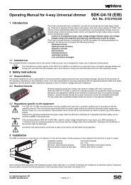
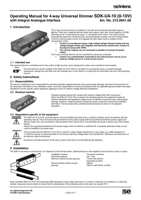
1 Introduction<br />
The 4-<strong>way</strong> universal dimmer is suitable <strong>for</strong> use with all conventional dimmable types of<br />
lighting. There are 4 separate dimmer inputs and outputs, each with a load capacity of 570W.<br />
Dimming circuit 1 must al<strong>way</strong>s be used, i.e. connected to the mains. The control circuits<br />
automatically detect the connected load, and automatically change over from <strong>for</strong>ward phase<br />
control to reverse phase control, and regulate the light output using a suitable control<br />
characteristic (Ueff).<br />
• Control of incandescent lamps, high-voltage halogen filament lamps and low<br />
voltage halogen lamps with magnetic and electronic trans<strong>for</strong>mers. Control of<br />
fluorescent lamps with VIP90.<br />
• Two dimmer outputs can be connected in parallel to increase the power<br />
output.<br />
The 4-<strong>way</strong> universal dimmer can be controlled by various bus protocols:<br />
• Control via a potentiometer connected to the internal power source, by an<br />
external voltage source or a sink-current source.<br />
1.1 Intended use<br />
The universal dimmer is intended only <strong>for</strong> the control of light sources, and is designed <strong>for</strong> indoor use in electrical control panels.<br />
Note<br />
The manufacturer (and/or supplier of the <strong>SDK</strong>-<strong>U4</strong>-<strong>10</strong> (0-<strong>10</strong>V)) is not liable <strong>for</strong> any personal injury or property damage<br />
whatsoever, arising from use other than the intended use or from failure to comply with the in<strong>for</strong>mation set out in this operating<br />
manual.<br />
2 Safety Instructions<br />
2.1 Responsibilities<br />
The person installing the unit is responsible <strong>for</strong> ensuring protection against personal injury and property damage, and also <strong>for</strong> the provision of<br />
the necessary in<strong>for</strong>mation to the installation owner. He is also responsible <strong>for</strong> ensuring compliance with the applicable general health and safety<br />
regulations and the specific safety regulations applying to work on medium-voltage electrical installations.<br />
2.2 Residual hazards<br />
Potential residual hazard from contact with medium-voltage (230 VAC) conductors.<br />
When the <strong>SDK</strong>-<strong>U4</strong>-<strong>10</strong> (0-<strong>10</strong>V) is used <strong>for</strong> its intended purpose, the equipment meets all<br />
relevant standards and regulations relating to the avoidance of personal injury and property<br />
damage. However, residual hazards arising from power-conductors cannot be completely<br />
eliminated. The key areas with a potential residual hazard are shown in the adjacent<br />
illustration.<br />
2.3 Regulations specific to the equipment<br />
DANGER!<br />
Attention!<br />
Attention!<br />
The <strong>SDK</strong>-<strong>U4</strong>-<strong>10</strong> (0-<strong>10</strong>V) universal dimmer must be installed and used only in a perfect condition and in accordance with the<br />
operating manual. The unit must be disconnected from the power supply be<strong>for</strong>e any electrical terminals (power supply and<br />
dimmer output, etc.) are connected or disconnected. Work carried out on live terminals can result in severe injury from electric<br />
shocks.<br />
Output LD is not disconnected from the power supply when the dimmer is switched off. A separate automatic safety cut-out<br />
must be installed in the power feed.<br />
If the universal dimmer <strong>SDK</strong>-<strong>U4</strong>-<strong>10</strong> (0-<strong>10</strong>V) is used <strong>for</strong> a high voltage trans<strong>for</strong>mer <strong>for</strong> neon signs, so a 30W resistance of<br />
1.5 kOhms must be connected parallel on the primary side (low voltage side) of the trans<strong>for</strong>mer. Otherwise the trans<strong>for</strong>mer or<br />
the dimmer might be destroyed.<br />
Connection and disconnection of the load or parts of the load is not permitted during operation.<br />
3 Installation<br />
The <strong>SDK</strong> is mounted on a top-hat rail. It is clipped in to the rail from below. Gentle pressure is then applied to the top front to snap it in place.<br />
Installation position:<br />
Horizontal spacing:<br />
Minimum vertical rail grid spacing:<br />
Recommended vertical rail grid<br />
spacing:<br />
Terminals horizontal<br />
min. 1mm<br />
115mm (90+25mm)<br />
(excluding conduit)<br />
160mm<br />
160mm (with 40mm conduit)<br />
Each individual <strong>SDK</strong>-<strong>U4</strong>-<strong>10</strong> (0-<strong>10</strong>V) generates 23W dissipation power under rated load. If a number of dimmers are installed in an electrical<br />
cabinet, measures must be taken to ensure that the temperature of the individual control units does not exceed 70°C.<br />
se Lightmanagement AG<br />
CH-8957 Spreitenbach 11557e V7.1
<strong>SDK</strong>-<strong>U4</strong>-<strong>10</strong> (0-<strong>10</strong>V) <strong>Operating</strong> <strong>Manual</strong> 2<br />
4 Control Modes<br />
The <strong>SDK</strong> can be controlled by a standard potentiometer, a voltage source or a sink-current source. The following illustrations show the<br />
connections <strong>for</strong> dimmer circuit 1.<br />
4.1 Auto OFF mode<br />
When DIP switch 7 is in the position shown, the Auto OFF function is activated, i.e. with an input voltage < 0.6 V, the output is switched off. This<br />
function can be deactivated by changing the position of DIP switch 7.<br />
1 2 3 4 5 6 7 8 9 <strong>10</strong><br />
ON<br />
1 2 3 4 5 6 7 8 9 <strong>10</strong><br />
ON<br />
1 2 3 4 5 6 7 8 9 <strong>10</strong><br />
ON<br />
<strong>SDK</strong>-<strong>U4</strong>-<strong>10</strong> (0-<strong>10</strong>V)<br />
1 Signal GND<br />
2 Analog IN 1<br />
3 Analog IN 2<br />
4 Analog IN 3<br />
5 Analog IN 4<br />
6 +<strong>10</strong>V OUT<br />
7 OFF1<br />
8 OFF2<br />
9 OFF3<br />
<strong>10</strong> OFF4<br />
11 Power GND<br />
12 +24V COM<br />
13 HS OUT 1<br />
14 HS OUT 2<br />
15 HS OUT 3<br />
16 HS OUT 4<br />
<strong>10</strong>k<br />
0...<strong>10</strong>V<br />
Control by standard potentiometer Control by external voltage source Control by sink-current source (e.g. EIB)<br />
4.2 Using a N/O contact to switch On and Off<br />
The <strong>SDK</strong> has a master ON/OFF function, allowing it to be switched off independently of the applied control voltage. The relevant output is<br />
switched off, if a N/O contact connects the relevant control input 7-<strong>10</strong> (OFF1 – OFF4) to GND.<br />
1 2 3 4 5 6 7 8 9 <strong>10</strong><br />
ON<br />
<strong>SDK</strong>-<strong>U4</strong>-<strong>10</strong> (0-<strong>10</strong>V)<br />
The described ON/OFF function naturally<br />
applies in all control modes (potentiometer,<br />
voltage source, sink-current source), with DIP<br />
switch 7 set to ON in each case.<br />
1 Signal GND<br />
2 Analog IN 1<br />
3 Analog IN 2<br />
4 Analog IN 3<br />
5 Analog IN 4<br />
6 +<strong>10</strong>V OUT<br />
7 OFF1<br />
8 OFF2<br />
9 OFF3<br />
<strong>10</strong> OFF4<br />
11 Power GND<br />
12 +24V COM<br />
13 HS OUT 1<br />
14 HS OUT 2<br />
15 HS OUT 3<br />
16 HS OUT 4<br />
<strong>10</strong>k<br />
Using a N/O contact to switch off<br />
On = N/O contact open<br />
5 Load Circuit<br />
MAX.<br />
<strong>10</strong>A<br />
PE<br />
230V 50Hz<br />
L N<br />
<strong>SDK</strong>-<strong>U4</strong>-<strong>10</strong><br />
N<br />
L<br />
PE<br />
N<br />
L<br />
N<br />
L<br />
N<br />
L<br />
The 4-<strong>way</strong> universal dimmer is capable of<br />
controlling 230V incandescent lamps, low<br />
voltage halogen lamps with electronic or<br />
magnetic trans<strong>for</strong>mers or fluorescent lamps<br />
with VIP90 up to a maximum current of 2.5 A<br />
(570 W). The dimmed voltage is present at<br />
output "LD". The universal dimmer uses<br />
transistor circuitry to control the output voltage.<br />
230V<br />
13 HS OUT 1<br />
11 Power GND<br />
12 +24V COM<br />
- +<br />
24V DC<br />
0-230V<br />
LD<br />
14 HS OUT 2<br />
230V<br />
0- 230V<br />
N<br />
PE<br />
11 Power GND<br />
LD<br />
15 HS OUT 3<br />
11 Power GND<br />
LD<br />
16 HS OUT 4<br />
11 Power GND<br />
LD<br />
To control fluorescent lamps with VIP90, the<br />
heating circuit (230V at terminal L of the<br />
VIP90) is switched on by a 24V relay, which is<br />
switched by output HS Out1 (terminal 13).<br />
230V<br />
0-230V<br />
N<br />
PE<br />
VG<br />
electronic<br />
trans<strong>for</strong>mer<br />
L L N 5 6<br />
1 2 3 4<br />
VIP 90/..<br />
18 - 58W<br />
FLUORESCENT LAMP<br />
with VIP90<br />
INCANDESCENT<br />
LAMP<br />
LOW-VOLTAGE-<br />
HALOGEN LAMP<br />
5.1 Parallel power connection<br />
To increase the power, two dimming circuits ( 1+2 and 3+4 ) can be connected in parallel. ( 2 x 570W = 1140W ).<br />
• The circuits connected together must be in the same phase.<br />
• Set DIP switches as described in Section 6.<br />
• On the power section, the contacts of the common dimming circuits must be connected together (L with L, N with N and LD with LD).<br />
11557e V7.1<br />
se Lightmanagement AG<br />
CH-8957 Spreitenbach
3 <strong>SDK</strong>-<strong>U4</strong>-<strong>10</strong> (0-<strong>10</strong>V) <strong>Operating</strong> <strong>Manual</strong><br />
6 DIP-switch settings:<br />
Switch: Function: "OFF" position: (up) "ON" position: (pushed back)<br />
DIP 1 1 ⎜⎜ 2 Circuits 1 + 2 not connected in parallel Circuits 1 + 2 connected in parallel<br />
DIP 2 3 ⎜⎜ 4 Circuits 3 + 4 not connected in parallel Circuits 3 + 4 connected in parallel<br />
DIP 3 fast Slow stepped response (dimming speed) Fast stepped response (dimming speed)<br />
DIP 4 min. limit Min. lighting value 0% Min. lighting value 30%<br />
DIP 5 max. limit. Max. lighting value <strong>10</strong>0% Max. lighting value 90%<br />
DIP 6 VIP90 No preheating Preheating time 1.5 s<br />
DIP 7 man. OFF <strong>Dimmer</strong> switches off at control voltage < 0.6 V No On/Off switching threshold at 0.6 V (manual)<br />
DIP 8 -- not used not used<br />
DIP 9 -- not used not used<br />
DIP <strong>10</strong> sink Control via control voltage or potentiometer Control via sink-current source<br />
To switch 1:<br />
Attention!<br />
To switch 2:<br />
To switch 3:<br />
To switch 4:<br />
Attention!<br />
The control signal from circuit 1 also controls circuit 2 with the same values.<br />
When two circuits are connected in parallel, both circuits must be connected to the same phase. If the two circuits are connected<br />
to different phases, the dimmer will be instantly destroyed when switched in parallel.<br />
The control signal from circuit 3 also controls circuit 4 with the same values. Note the above warning.<br />
In normal situations, the slow-stepped response (ramp 400ms) is used. For effect lighting, the response can be shortened (ramp<br />
<strong>10</strong>0ms).<br />
This switch is used to increase the minimum output of the dimmer from 0% to 30%. This value is output at a potentiometer<br />
setting of 0% or an input voltage of 0V. A desired basic level of brightness can be ensured by increasing the minimum lighting<br />
value.<br />
If the minimum lighting value is set to 30%, the output voltage can reach a dangerous level, even if there is no input voltage<br />
(potentiometer set to 0V). The safety cut-out, mains-side of the dimmer, must be switched off be<strong>for</strong>e changing the lamp.<br />
To switch 5: This switch is used to reduce the maximum output of the dimmer from <strong>10</strong>0% to 90%. This value is output at a potentiometer<br />
setting of <strong>10</strong>0% or an input voltage of <strong>10</strong>V. Reduction of the maximum lighting value to 90% extends lamp life.<br />
To switch 6: Fluorescent lamps with VIP90 need to be preheated.<br />
To switch 7: The use of the Auto-OFF function is described in Section 4.<br />
To switch <strong>10</strong>: The various control modes are described in Section 4.<br />
7 LED Indicators on the <strong>Dimmer</strong><br />
The dimmer has 6 LEDs on the interface section and 4 LEDs on the power section:<br />
Interface section:<br />
• Red LED (Power) 230V power supply<br />
• Yellow LED (Run) <strong>Dimmer</strong> operational<br />
• Green LED 1-4 (Status D1-D4) Status indicator, circuits 1-4<br />
Red LED Off: No voltage at interface section<br />
On: Voltage at interface section.<br />
Yellow LED Off: Interface section not OK<br />
Flashing: slow: Interface section OK and<br />
Communication OK<br />
fast: Interface section OK, but<br />
Communication not OK<br />
Green LED: Off: Relevant output is OFF.<br />
On: Relevant output is ON.<br />
Flashing: 1x, then interval: Over-current<br />
2x, then interval: Over-voltage.<br />
3x, then interval: Overheating<br />
4x, then interval: Load not detected by dimmer<br />
Power section:<br />
Green LED 1<br />
Green LED 1-4<br />
On:<br />
Off:<br />
(Run) Status indicator, circuits<br />
1-4<br />
Dimming circuit on.<br />
Dimming circuit off.<br />
se Lightmanagement AG<br />
CH-8957 Spreitenbach 11557e V7.1
<strong>SDK</strong>-<strong>U4</strong>-<strong>10</strong> (0-<strong>10</strong>V) <strong>Operating</strong> <strong>Manual</strong> 4<br />
8 Fault Finding and Elimination<br />
Fault<br />
Remedy<br />
Lamp does not brighten. • Check the bus voltage on the <strong>SDK</strong> (red LED must come on).<br />
• Dimming circuit 1 must al<strong>way</strong>s be connected to the mains.<br />
• Check control voltage. Set DIP switch 1 in accordance with the control<br />
mode.<br />
• 0V possibly not connected.<br />
• If the yellow LED flashes at a fast rate, one of the dimmer circuits is not<br />
receiving power or the dimmer is faulty.<br />
Lamps do not dim completely. • Minimum lighting value not 0% (DIP switch 4 is ON).<br />
<strong>Dimmer</strong> cannot be controlled up to <strong>10</strong>0%. • Maximum lighting value not <strong>10</strong>0% (DIP switch 5 is ON).<br />
Green LED (Run) flashes 1x • <strong>Dimmer</strong> has over-current. Reduce load, possibly connect in parallel.<br />
Green LED (Run) flashes 2x • <strong>Dimmer</strong> has over-voltage. Check installation.<br />
Green LED (Run) flashes 3x. • <strong>Dimmer</strong> overheating. Improve cooling.<br />
Light goes out and green LED (Run) flashes 4x. • <strong>Dimmer</strong> has not recognised type of load. Load detection can be repeated by<br />
switching On – Off – On within one minute.<br />
9 Technical Data<br />
Dimensions:<br />
44<br />
90<br />
234<br />
Electrical data: per channel<br />
Mains voltage: 230 V ±<strong>10</strong>%<br />
Mains frequency:<br />
50 / 60 Hz<br />
Preliminary fuse:<br />
<strong>10</strong> A max.<br />
Dimming output technology: Transistor-driven <strong>for</strong>ward phase<br />
control / reverse phase control<br />
Maximum load, dimming<br />
output:<br />
570 W / VA (2.5A) resistive /<br />
inductive / capacitive<br />
Minimum load, dimming 5 W resistive<br />
output:<br />
Leakage power at rated load: 5.7 W at rated load<br />
Leakage power on standby: 1.4 W<br />
Cooling:<br />
Natural air circulation<br />
No-load voltage:<br />
Approx. 55 Vrms<br />
Short-circuit protection: Electronic fast cut-off<br />
Overload protection:<br />
Temperature monitoring. (trigger<br />
value approx. 85°C)<br />
Symmetry errors:<br />
Not measurable<br />
Impulse switching flank: <strong>10</strong>0µs, with incandescent-lamp at<br />
rated load<br />
Operational and fault indicator: Green "Run" LED per channel<br />
Keys (integrated single-key<br />
control):<br />
On / brighter / dimmer. (<strong>for</strong> test<br />
purposes at initial start-up)<br />
Insulation:<br />
2500 V between interface unit<br />
and dimmer<br />
Switch-on delay:<br />
approx. 1s (mains switch-on)<br />
Type<br />
Article number<br />
<strong>SDK</strong>-<strong>U4</strong>-<strong>10</strong> (0-<strong>10</strong>V)<br />
215.0041.00<br />
Mechanical data:<br />
Case:<br />
Steel sheet with aluminium cooler<br />
Dimensions:<br />
Width: 234 mm (with screws)<br />
Height: 90 mm<br />
Depth: 44 mm (from top-hat prof.)<br />
Weight:<br />
850 g<br />
Installation:<br />
On DIN top-hat profile rails 35 mm<br />
Mains power connection: 4 plug-in terminals max. 2.5 mm²<br />
Load connection:<br />
1 plug-in terminal max. 2.5 mm²<br />
Control connections:<br />
Plug-in terminals max. 0.8 mm²<br />
Ambient conditions:<br />
Ambient temperature:<br />
ta 0-40 °C max. Do not block<br />
airflow at cooler.<br />
Storage temperature:<br />
70 °C max.<br />
Air humidity:<br />
<strong>10</strong>%...80% relative air humidity,<br />
non-condensing<br />
Case temperature:<br />
tc 70 °C max.<br />
IP protection:<br />
IP20<br />
Control:<br />
Control voltage:<br />
0...<strong>10</strong> V, electrically separated<br />
Input resistance:<br />
200 kΩ<br />
Potentiometer:<br />
External, <strong>10</strong> kΩ<br />
Potentiometer lead:<br />
3-core, non-screened<br />
Ø 0.5 mm 2 . Lead length<br />
max. <strong>10</strong>0 m<br />
Control characteristic:<br />
U eff - linear<br />
Sink current control:<br />
0...<strong>10</strong> V, 1.2 mA<br />
Adjustment time analogue: approx. 400 ms (spec. value <strong>for</strong>transfer<br />
response)<br />
Operational and fault indicator: 6 LED (Power, Run, 4 x Status)<br />
CE mark:<br />
as per 89/336/EWG and 73/23/EWG<br />
EN 60669-2-1<br />
Safety requirements<br />
EN 55015<br />
Interference transmission<br />
EN 55014-2 (VDE 0875) Radio interference<br />
EN 6<strong>10</strong>00-3-2<br />
Harmonics<br />
Would you like more «varintens» in<strong>for</strong>mation? Visit our web site!<br />
www.se-ag.ch<br />
e-mail: info@se-ag.ch<br />
se Lightmanagement AG<br />
Güterstrasse 11, CH-8957 Spreitenbach,<br />
Switzerland<br />
Tel. +41 56 418 76 11, Fax +41 56 401 49 86<br />
11557e V7.1<br />
se Lightmanagement AG<br />
CH-8957 Spreitenbach