IEEE Hybrid Grounding
IEEE Hybrid Grounding
IEEE Hybrid Grounding

Create successful ePaper yourself
Turn your PDF publications into a flip-book with our unique Google optimized e-Paper software.
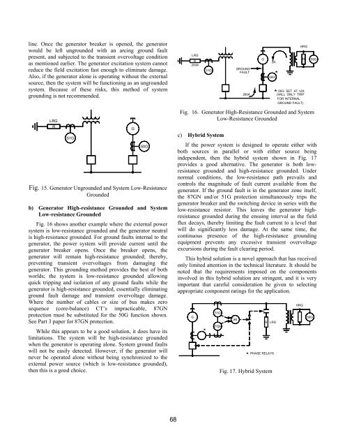
line. Once the generator breaker is opened, the generator<br />
would be left ungrounded with an arcing ground fault<br />
present, and subjected to the transient overvoltage condition<br />
as mentioned earlier. The generator excitation system cannot<br />
reduce the field excitation fast enough to eliminate damage.<br />
Also, if the generator alone is operating without the external<br />
source, then the system will be functioning as an ungrounded<br />
system. Because of these risks, this method of system<br />
grounding is not recommended.<br />
LRG<br />
R<br />
51G<br />
G<br />
50G<br />
Fig. 15. Generator Ungrounded and System Low-Resistance<br />
Grounded<br />
b) Generator High-resistance Grounded and System<br />
Low-resistance Grounded<br />
Fig. 16 shows another example where the external power<br />
system is low-resistance grounded and the generator neutral<br />
is high-resistance grounded. For ground faults internal to the<br />
generator, the power system will provide current until the<br />
generator breaker opens. Once the breaker opens, the<br />
generator will remain high-resistance grounded; thereby,<br />
preventing transient overvoltages from damaging the<br />
generator. This grounding method provides the best of both<br />
worlds; the system is low-resistance grounded allowing<br />
quick tripping and isolation of any ground faults while the<br />
generator is high-resistance grounded, essentially eliminating<br />
ground fault damage and transient overvoltage damage.<br />
Where the number of cables or size of bus makes zero<br />
sequence (core-balance) CT’s impracticable, 87GN<br />
protection must be substituted for the 50G function shown.<br />
See Part 3 paper for 87GN protection.<br />
While this appears to be a good solution, it does have its<br />
limitations. The system will be high-resistance grounded<br />
when the generator is operating alone. System ground faults<br />
will not be easily detected. However, if the generator will<br />
never be operated alone without being synchronized to the<br />
external power source (which is low-resistance grounded),<br />
then this is a good choice.<br />
LRG<br />
R<br />
200A<br />
51G<br />
GROUND<br />
FAULT<br />
200A<br />
G<br />
X<br />
2A<br />
50G<br />
*<br />
HRG<br />
R<br />
50G SET AT >2A<br />
*(WILL ONLY TRIP<br />
FOR INTERNAL<br />
GROUND FAULT)<br />
Fig. 16. Generator High-Resistance Grounded and System<br />
Low-Resistance Grounded<br />
c) <strong>Hybrid</strong> System<br />
If the power system is designed to operate either with<br />
both sources in parallel or with either source being<br />
independent, then the hybrid system shown in Fig. 17<br />
provides a good alternative. The generator is both lowresistance<br />
grounded and high-resistance grounded. Under<br />
normal conditions, the low-resistance path prevails and<br />
controls the magnitude of fault current available from the<br />
generator. If the ground fault is in the generator zone itself,<br />
the 87GN and/or 51G protection simultaneously trips the<br />
generator breaker and the switching device in series with the<br />
low-resistance resistor. This leaves the generator highresistance<br />
grounded during the ensuing interval as the field<br />
flux decays, thereby limiting the fault current to a level that<br />
will do significantly less damage. At the same time, the<br />
continuous presence of the high-resistance grounding<br />
equipment prevents any excessive transient overvoltage<br />
excursions during the fault clearing period.<br />
This hybrid solution is a novel approach that has received<br />
only limited attention in the technical literature. It should be<br />
noted that the requirements imposed on the components<br />
involved in this hybrid solution are stringent, and it is very<br />
important that careful consideration be given to selecting<br />
appropriate component ratings for the application.<br />
G<br />
*<br />
51G<br />
86<br />
*<br />
R LRG<br />
PHASE RELAYS<br />
Fig. 17. <strong>Hybrid</strong> System<br />
HRG<br />
59G<br />
59G<br />
68