IEEE Hybrid Grounding
IEEE Hybrid Grounding
IEEE Hybrid Grounding

You also want an ePaper? Increase the reach of your titles
YUMPU automatically turns print PDFs into web optimized ePapers that Google loves.
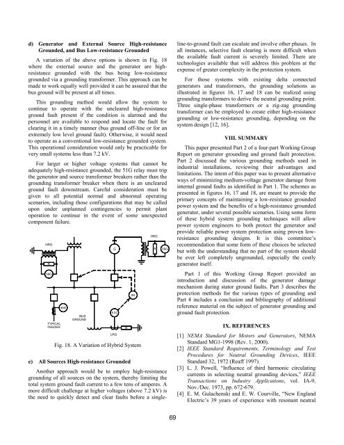
d) Generator and External Source High-resistance<br />
Grounded, and Bus Low-resistance Grounded<br />
A variation of the above options is shown in Fig. 18<br />
where the external source and the generator are highresistance<br />
grounded with the bus being low-resistance<br />
grounded via a grounding transformer. This approach can be<br />
made to work equally well provided it can be assured that the<br />
bus ground will be present at all times.<br />
This grounding method would allow the system to<br />
continue to operate with the uncleared high-resistance<br />
ground fault present if the condition is alarmed and the<br />
personnel are available to respond and locate the fault for<br />
clearing it in a timely manner (bus ground off-line or for an<br />
extremely low level ground fault). Otherwise, it would need<br />
to operate as a conventional low-resistance grounded system.<br />
This operational consideration would only be practicable for<br />
very small systems less than 7.2 kV.<br />
For larger or higher voltage systems that cannot be<br />
adequately high-resistance grounded, the 51G relay must trip<br />
the generator and source transformer breakers rather than the<br />
grounding transformer breaker when there is an uncleared<br />
ground fault downstream. Careful consideration must be<br />
given to all potential normal and abnormal operating<br />
scenarios, including those configurations that may be called<br />
upon under unplanned contingencies to permit plant<br />
operation to continue in the event of some unexpected<br />
component failure.<br />
HRG<br />
R<br />
59G<br />
TYPICAL<br />
FEEDER<br />
50G<br />
BUS<br />
GROUND<br />
G<br />
51G<br />
LRG<br />
Fig. 18. A Variation of <strong>Hybrid</strong> System<br />
R<br />
86<br />
HRG<br />
R<br />
59G<br />
e) All Sources High-resistance Grounded<br />
Another approach would be to employ high-resistance<br />
grounding of all sources on the system, thereby limiting the<br />
total system ground fault current to a few tens of amperes. A<br />
more difficult challenge at higher voltages (above 7.2 kV) is<br />
the need to quickly detect and clear faults before a singleline-to-ground<br />
fault can escalate and involve other phases. In<br />
all instances, selective fault clearing is more difficult when<br />
the available fault current is severely limited. There are<br />
technologies available that will address this problem at the<br />
expense of greater complexity in the protection system.<br />
For those systems with existing delta connected<br />
generators and transformers, the grounding solutions as<br />
illustrated in figures 16, 17 and 18 can be realized using<br />
grounding transformers to derive the neutral grounding point.<br />
Three single-phase transformers or a zig-zag grounding<br />
transformer can be employed to create either high-resistance<br />
grounding or low-resistance grounding, depending on the<br />
system design [12, 16].<br />
VIII. SUMMARY<br />
This paper presented Part 2 of a four-part Working Group<br />
Report on generator grounding and ground fault protection.<br />
Part 2 discussed the various grounding methods used in<br />
industrial installations, reviewing their advantages and<br />
limitations. The intent of this paper was to present alternative<br />
ways of minimizing medium-voltage generator damage from<br />
internal ground faults as identified in Part 1. The schemes as<br />
presented in figures 16, 17 and 18, are meant to provide the<br />
primary concepts of maintaining a low-resistance grounded<br />
power system and the benefits of a high-resistance grounded<br />
generator, under several possible scenarios. Using some form<br />
of these hybrid system grounding techniques will allow<br />
power system engineers to both protect the generator and<br />
provide reliable power system protection using proven lowresistance<br />
grounding designs. It is this committee’s<br />
recommendation that some form of these choices be selected<br />
but with the understanding that no part of the system should<br />
be ever left completely ungrounded, especially the costly<br />
generator itself.<br />
Part 1 of this Working Group Report provided an<br />
introduction and discussion of the generator damage<br />
mechanism during stator ground faults. Part 3 describes the<br />
protection methods for the various types of grounding and<br />
Part 4 includes a conclusion and bibliography of additional<br />
reference material on the subject of generator grounding and<br />
ground fault protection.<br />
IX. REFERENCES<br />
[1] NEMA Standard for Motors and Generators, NEMA<br />
Standard MG1-1998 (Rev. 1, 2000).<br />
[2] <strong>IEEE</strong> Standard Requirements, Terminology and Test<br />
Procedures for Neutral <strong>Grounding</strong> Devices, <strong>IEEE</strong><br />
Standard 32, 1972 (Reaff 1997).<br />
[3] L. J. Powell, “Influence of third harmonic circulating<br />
currents in selecting neutral grounding devices,” <strong>IEEE</strong><br />
Transactions on Industry Applications, vol. IA-9,<br />
Nov./Dec. 1973, pp. 672-679.<br />
[4] E. M. Gulachenski and E. W. Courville, “New England<br />
Electric’s 39 years of experience with resonant neutral<br />
69